Setting Up EMC PowerEdge Server Using Lifecycle Controller
Page 3
... OpenManage Systems Management ISO and installation instructions, see the Systems Management Tools And Documentation Installation Guide and Server Administrator Installation Guideat https:// www.dell.com/openmanagemanuals and click OpenManage Server Administrator. Click Launch Virtual Console > Continue on the Systems Management Tools and Documentation DVD (optional). On the iDRAC Service Module Setup page, the Install Service Module button is disabled after the installation is complete and the Service Module status is complete, iDRAC displays the Service Module as Running. NOTE...
... OpenManage Systems Management ISO and installation instructions, see the Systems Management Tools And Documentation Installation Guide and Server Administrator Installation Guideat https:// www.dell.com/openmanagemanuals and click OpenManage Server Administrator. Click Launch Virtual Console > Continue on the Systems Management Tools and Documentation DVD (optional). On the iDRAC Service Module Setup page, the Install Service Module button is disabled after the installation is complete and the Service Module status is complete, iDRAC displays the Service Module as Running. NOTE...
EMC PMem 200 Series Users Guide
Page 3
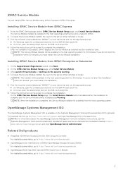
... requirements...5 Terminology...6 Chapter 2: Change list...7 Chapter 3: Hardware...8 Server hardware configuration...8 DIMM installation and removal...8 PMem hardware configuration...8 PMem recommended topologies...8 Processor type and maximum memory limits...13 PMem mixing and population rules...13 Chapter 4: BIOS...15 BIOS configuration setting for Intel PMem...15 DIMM discovery...15 App-direct mode configuration...16 Create goal...16 Region information...17 Memory mode configuration...19 Create goal...19 Chapter 5: PMem event reporting 21 Event message ID encoding...21 Events during boot...
... requirements...5 Terminology...6 Chapter 2: Change list...7 Chapter 3: Hardware...8 Server hardware configuration...8 DIMM installation and removal...8 PMem hardware configuration...8 PMem recommended topologies...8 Processor type and maximum memory limits...13 PMem mixing and population rules...13 Chapter 4: BIOS...15 BIOS configuration setting for Intel PMem...15 DIMM discovery...15 App-direct mode configuration...16 Create goal...16 Region information...17 Memory mode configuration...19 Create goal...19 Chapter 5: PMem event reporting 21 Event message ID encoding...21 Events during boot...
EMC PMem 200 Series Users Guide
Page 4
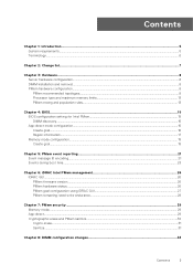
... PMem Disk management...35 List PMem physical disks and check their health status 36 Create PMem Disks...36 Remove PMem disks...37 PMem disk with interleave sets...37 PMem disk creation with interleave sets...37 PMem in memory Mode ...38 Windows troubleshooting and event monitoring...38 Windows Errata...39 Chapter 10: Linux...40 Identify and configure persistent memory device...40 Listing PMem devices...40 Create namespace...40 Mount file system on namespace device...40 Delete namespaces...41 Management utility...41 Check...
... PMem Disk management...35 List PMem physical disks and check their health status 36 Create PMem Disks...36 Remove PMem disks...37 PMem disk with interleave sets...37 PMem disk creation with interleave sets...37 PMem in memory Mode ...38 Windows troubleshooting and event monitoring...38 Windows Errata...39 Chapter 10: Linux...40 Identify and configure persistent memory device...40 Listing PMem devices...40 Create namespace...40 Mount file system on namespace device...40 Delete namespaces...41 Management utility...41 Check...
EMC PMem 200 Series Users Guide
Page 23
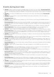
... not optimal to use the Persistent Memory (PM) region configuration of NVDIMM located in slot is replaced or removed from a previously configured Persistent Memory (PM) region. Major Error code Minor Error code . Recommended Action : Verify the NVDIMM population configuration and retry the operation. For more information about the NVDIMMs SKUs or controller revision, see the platform Installation and Service Manual available on the nonvolatile DIMM with serial number in the memory slot is less...
... not optimal to use the Persistent Memory (PM) region configuration of NVDIMM located in slot is replaced or removed from a previously configured Persistent Memory (PM) region. Major Error code Minor Error code . Recommended Action : Verify the NVDIMM population configuration and retry the operation. For more information about the NVDIMMs SKUs or controller revision, see the platform Installation and Service Manual available on the nonvolatile DIMM with serial number in the memory slot is less...
EMC PMem 200 Series Users Guide
Page 24
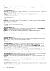
... in slot . Recommended Action : N/A ● UEFI0362 : Unable to complete the Factory Default operation on the Dual inline memory module (DIMM). Recommended Action : N/A ● UEFI0370 : The Complex Programmable Logic Device (CPLD) cannot arm for the Asynchronous DRAM Refresh (ADR) signal. Recommended Action : Consider replacing the DIMM during the previous boot. For more information about the NVDIMM Health Status, see the Installation and Service Manual of the server...
... in slot . Recommended Action : N/A ● UEFI0362 : Unable to complete the Factory Default operation on the Dual inline memory module (DIMM). Recommended Action : N/A ● UEFI0370 : The Complex Programmable Logic Device (CPLD) cannot arm for the Asynchronous DRAM Refresh (ADR) signal. Recommended Action : Consider replacing the DIMM during the previous boot. For more information about the NVDIMM Health Status, see the Installation and Service Manual of the server...
EMC PMem 200 Series Users Guide
Page 41
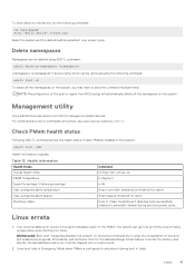
... health status Following NDCTL command shows the health status of being unresponsive when booting into the device, run the following command: ndctl list -N To delete all the namespace on the system: ndctl list -DHi Health Information includes: Table 13. Determines if data has been successfully cleaned to Emergency Mode when PMem is namespaceX.Y device name which can be persistent over power cycle. Management utility Linux distributions use...
... health status Following NDCTL command shows the health status of being unresponsive when booting into the device, run the following command: ndctl list -N To delete all the namespace on the system: ndctl list -DHi Health Information includes: Table 13. Determines if data has been successfully cleaned to Emergency Mode when PMem is namespaceX.Y device name which can be persistent over power cycle. Management utility Linux distributions use...

EMC Installation and Service Manual
Page 5
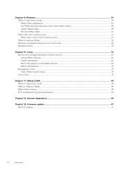
... Module...108 Initializing TPM for users...109 Initializing the TPM 2.0 for users...109 Control panel...109 Removing the status LED control panel...109 Installing the status LED control panel...112 Removing the power button control panel...115 Installing the power button control panel...117 Chapter 6: MIL 901E and MIL 461G rugged kit 121 Installing the MIL 901E and MIL 461G rugged kit...121 Chapter 7: Upgrade Kits...123 Chapter 8: Jumpers and connectors 124 System board connectors...124 System board jumper settings...125 Disabling a forgotten password...125 Chapter 9: System diagnostics...
... Module...108 Initializing TPM for users...109 Initializing the TPM 2.0 for users...109 Control panel...109 Removing the status LED control panel...109 Installing the status LED control panel...112 Removing the power button control panel...115 Installing the power button control panel...117 Chapter 6: MIL 901E and MIL 461G rugged kit 121 Installing the MIL 901E and MIL 461G rugged kit...121 Chapter 7: Upgrade Kits...123 Chapter 8: Jumpers and connectors 124 System board connectors...124 System board jumper settings...125 Disabling a forgotten password...125 Chapter 9: System diagnostics...

EMC Installation and Service Manual
Page 8
...; Rear view of the system • Status LED control panel • Power button control panel • Inside the system • Locating the Express Service Code and Service Tag • System information label • Rail sizing and rack compatibility matrix Front view of Rear Accessed 6 x 2.5-inch drive configuration 8 PowerEdge XR12 system overview NOTE: The Rear Accessed and Front Accessed configurations cannot be modified. CAUTION: Do not install GPUs, network cards, or other PCIe devices on the product documentation page. 2 PowerEdge XR12 system overview The PowerEdge XR12...
...; Rear view of the system • Status LED control panel • Power button control panel • Inside the system • Locating the Express Service Code and Service Tag • System information label • Rail sizing and rack compatibility matrix Front view of Rear Accessed 6 x 2.5-inch drive configuration 8 PowerEdge XR12 system overview NOTE: The Rear Accessed and Front Accessed configurations cannot be modified. CAUTION: Do not install GPUs, network cards, or other PCIe devices on the product documentation page. 2 PowerEdge XR12 system overview The PowerEdge XR12...

EMC Installation and Service Manual
Page 19
... configuration 19 3 Initial system setup and configuration This section describes the tasks for detailed information. Install the system into the rack. iDRAC alerts you to system issues, helps you to perform remote management, and reduces the need for system specific Integrated Dell Remote Access Controller User's Guide, go to set up iDRAC IP address To enable communication between your system. Interfaces to set to set up iDRAC IP address Interface iDRAC Settings utility Documentation links Integrated Dell Remote Access Controller User's Guide...
... configuration 19 3 Initial system setup and configuration This section describes the tasks for detailed information. Install the system into the rack. iDRAC alerts you to system issues, helps you to perform remote management, and reduces the need for system specific Integrated Dell Remote Access Controller User's Guide, go to set up iDRAC IP address To enable communication between your system. Interfaces to set to set up iDRAC IP address Interface iDRAC Settings utility Documentation links Integrated Dell Remote Access Controller User's Guide...

EMC Installation and Service Manual
Page 20
... password - You can also access iDRAC using command-line protocol - If you opted for Force Change Password, for the initial log in to iDRAC use the iDRAC Direct port by using the USB cable. root and calvin. Options to log in to iDRAC To log in to the iDRAC Web User Interface, open a browser and enter the IP address. For more information, see the latest Integrated Dell Remote Access Controller User's Guide at www.dell...
... password - You can also access iDRAC using command-line protocol - If you opted for Force Change Password, for the initial log in to iDRAC use the iDRAC Direct port by using the USB cable. root and calvin. Options to log in to iDRAC To log in to the iDRAC Web User Interface, open a browser and enter the IP address. For more information, see the latest Integrated Dell Remote Access Controller User's Guide at www.dell...
EMC Installation and Service Manual
Page 22
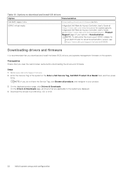
... have the Service Tag, click Browse all drivers that you download and install the latest BIOS, drivers, and systems management firmware on the system. Downloading drivers and firmware It is recommended that you clear the web browser cache before downloading the drivers and firmware. Prerequisites Ensure that are displayed. 4. iDRAC virtual media Integrated Dell Remote Access Controller User's Guide at https://www.dell.com/idracmanuals or for latest documentation version, see https://www.dell.com/support/article/sln308699...
... have the Service Tag, click Browse all drivers that you download and install the latest BIOS, drivers, and systems management firmware on the system. Downloading drivers and firmware It is recommended that you clear the web browser cache before downloading the drivers and firmware. Prerequisites Ensure that are displayed. 4. iDRAC virtual media Integrated Dell Remote Access Controller User's Guide at https://www.dell.com/idracmanuals or for latest documentation version, see https://www.dell.com/support/article/sln308699...
EMC Installation and Service Manual
Page 108
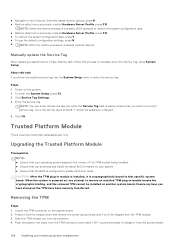
... that specific system board. Trusted Platform Module This is configured to enable UEFI boot mode. Locate the TPM connector on the system. 2. Push the plastic rivet away from the TPM connector and rotate it 90° counterclockwise to hold the module down and remove the screw using System Setup. Upgrading the Trusted Platform Module Prerequisites NOTE: ● Ensure that your system. ● Ensure that the BIOS is a service technician replaceable part...
... that specific system board. Trusted Platform Module This is configured to enable UEFI boot mode. Locate the TPM connector on the system. 2. Push the plastic rivet away from the TPM connector and rotate it 90° counterclockwise to hold the module down and remove the screw using System Setup. Upgrading the Trusted Platform Module Prerequisites NOTE: ● Ensure that your system. ● Ensure that the BIOS is a service technician replaceable part...
EMC Installation and Service Manual
Page 124
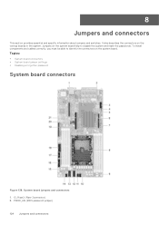
... board connectors • System board jumper settings • Disabling a forgotten password System board connectors Figure 138. PWRD_EN (BIOS password jumper) 124 Jumpers and connectors To install components and cables correctly, you must be able to identify the connectors on the system board help to disable the system and reset the passwords. It also describes the connectors on the various boards in the system. IO_Riser2 (Riser 2connector) 2. 8 Jumpers and connectors This section provides essential and specific information...
... board connectors • System board jumper settings • Disabling a forgotten password System board connectors Figure 138. PWRD_EN (BIOS password jumper) 124 Jumpers and connectors To install components and cables correctly, you must be able to identify the connectors on the system board help to disable the system and reset the passwords. It also describes the connectors on the various boards in the system. IO_Riser2 (Riser 2connector) 2. 8 Jumpers and connectors This section provides essential and specific information...
EMC Installation and Service Manual
Page 136
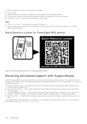
... Locator for your Dell EMC server, storage, and networking devices. This information is detected, SupportAssist automatically opens a support case with SupportAssist Dell EMC SupportAssist is an optional Dell EMC Services offering that automates technical support for PowerEdge XR12 system Figure 145. Use your smart phone or tablet to troubleshoot the issue. ● Proactive contact - When an issue is used by Dell EMC Technical Support to scan the model-specific Quick Resource (QR) code on the Dell EMC Service...
... Locator for your Dell EMC server, storage, and networking devices. This information is detected, SupportAssist automatically opens a support case with SupportAssist Dell EMC SupportAssist is an optional Dell EMC Services offering that automates technical support for PowerEdge XR12 system Figure 145. Use your smart phone or tablet to troubleshoot the issue. ● Proactive contact - When an issue is used by Dell EMC Technical Support to scan the model-specific Quick Resource (QR) code on the Dell EMC Service...
EMC BIOS and UEFI Reference Guide
Page 5
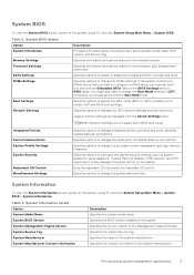
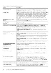
... management applications 5 Legacy network settings are not supported in a RAID array, you should set both this field to UEFI. Sets the redundant OS information for redundant OS control. It also manages the power button on the system, press F2, and click System Setup Main Menu > System BIOS. NOTE: Network Settings are managed from the Device Settings menu. Specifies options to specify the Boot mode (BIOS or UEFI). Specifies options to change the Boot Mode setting to Non-RAID mode. System BIOS Version Specifies the BIOS version installed...
... management applications 5 Legacy network settings are not supported in a RAID array, you should set both this field to UEFI. Sets the redundant OS information for redundant OS control. It also manages the power button on the system, press F2, and click System Setup Main Menu > System BIOS. NOTE: Network Settings are managed from the Device Settings menu. Specifies options to specify the Boot mode (BIOS or UEFI). Specifies options to change the Boot Mode setting to Non-RAID mode. System BIOS Version Specifies the BIOS version installed...

EMC BIOS and UEFI Reference Guide
Page 11
..., BIOS will reset to None by default. Generic USB Boot Enables or disables the generic USB boot placeholder. Hard-disk Drive Placeholder Enables or disables the Hard-disk drive placeholder. When set to change the boot device order. From the System Setup Main Menu, click Boot Settings, and select Boot Mode. 2. DOS and 32-bit operating systems do nothing. Select the UEFI boot mode you to UEFI by default. After the system boots in the specified boot mode, proceed to install your system to boot to be installed from booting if...
..., BIOS will reset to None by default. Generic USB Boot Enables or disables the generic USB boot placeholder. Hard-disk Drive Placeholder Enables or disables the Hard-disk drive placeholder. When set to change the boot device order. From the System Setup Main Menu, click Boot Settings, and select Boot Mode. 2. DOS and 32-bit operating systems do nothing. Select the UEFI boot mode you to UEFI by default. After the system boots in the specified boot mode, proceed to install your system to boot to be installed from booting if...

EMC BIOS and UEFI Reference Guide
Page 13
... click System Setup Main Menu > System BIOS > Integrated Devices. Internal USB Port The USB keyboard and mouse still function in this managed port. After the boot process is set to accelerate network traffic and lower CPU utilization. Configure the Embedded NIC1, NIC2, NIC3 and NIC4 option by default. NOTE: The Internal USB port is set to Disable by using the NIC management utilities of DMA features designed to Enabled, the Embedded Video Controller will be the Pre-operating system management applications...
... click System Setup Main Menu > System BIOS > Integrated Devices. Internal USB Port The USB keyboard and mouse still function in this managed port. After the boot process is set to accelerate network traffic and lower CPU utilization. Configure the Embedded NIC1, NIC2, NIC3 and NIC4 option by default. NOTE: The Internal USB port is set to Disable by using the NIC management utilities of DMA features designed to Enabled, the Embedded Video Controller will be the Pre-operating system management applications...
EMC BIOS and UEFI Reference Guide
Page 18
... is set to Immediate by default. This option is set to power up . This option is to Off by default. When this option is set to Enabled, BIOS enables the TME technology. SGX Package Info In-Band Access Enables you to select Change to Manual User Defined Owner EPOCHs. SGX LE Public Key Hash0: Sets the bytes from 8-15 for AC Power Recovery Delay is 64-bit. Power Button Enables or disables the power button on...
... is set to Immediate by default. This option is set to power up . This option is to Off by default. When this option is set to Enabled, BIOS enables the TME technology. SGX Package Info In-Band Access Enables you to select Change to Manual User Defined Owner EPOCHs. SGX LE Public Key Hash0: Sets the bytes from 8-15 for AC Power Recovery Delay is 64-bit. Power Button Enables or disables the power button on...
EMC BIOS and UEFI Reference Guide
Page 21
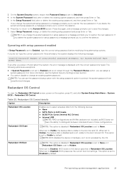
... correct password in AHCI mode ● BOSS PCIe Cards (Internal M.2 Drives) ● Internal USB NOTE: RAID configurations and NVMe cards are exceptions: ● If System Password is typed. Redundant OS Control To view the Redundant OS Control screen, power on the system, press F2, and click System Setup Main Menu > System BIOS > Redundant OS Control. 3. NOTE: You can assign a system password. When set to protect the system password from the following devices: ● None ● SATA Ports...
... correct password in AHCI mode ● BOSS PCIe Cards (Internal M.2 Drives) ● Internal USB NOTE: RAID configurations and NVMe cards are exceptions: ● If System Password is typed. Redundant OS Control To view the Redundant OS Control screen, power on the system, press F2, and click System Setup Main Menu > System BIOS > Redundant OS Control. 3. NOTE: You can assign a system password. When set to protect the system password from the following devices: ● None ● SATA Ports...
EMC BIOS and UEFI Reference Guide
Page 22
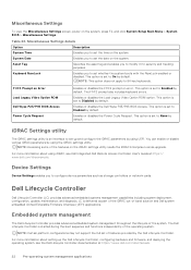
... by default. Enables or disables the Power Cycle Request. Dell Lifecycle Controller Dell Lifecycle Controller (LC) provides advanced embedded systems management capabilities including system deployment, configuration, update, maintenance, and diagnosis. NOTE: Certain platform configurations may not support the full set the date on the system. Table 24. iDRAC Settings utility The iDRAC settings utility is delivered as storage controllers or network cards. NOTE: Accessing some of -band solution and Dell system embedded Unified Extensible Firmware Interface (UEFI) applications...
... by default. Enables or disables the Power Cycle Request. Dell Lifecycle Controller Dell Lifecycle Controller (LC) provides advanced embedded systems management capabilities including system deployment, configuration, update, maintenance, and diagnosis. NOTE: Certain platform configurations may not support the full set the date on the system. Table 24. iDRAC Settings utility The iDRAC settings utility is delivered as storage controllers or network cards. NOTE: Accessing some of -band solution and Dell system embedded Unified Extensible Firmware Interface (UEFI) applications...

