Installation and Service Manual
Page 3
Rear view for PowerEdge XE9680 10 Left Control Panel (LCP)...11 Right Control Panel (RCP)...12 System configurations - Front view for PowerEdge XE9680 13 Inside the system...15 Locating the Express Service Code and Service Tag 17 System information label...17 Rail sizing and rack compatibility matrix...22 Chapter 3: Technical specifications 23 Chassis dimensions...24 System weight...25 Processor specifications...25 PSU specifications...25 Cooling fan specifications...26 Supported operating systems...27 System battery specifications...27 Expansion card riser specifications...27 Memory ...
Rear view for PowerEdge XE9680 10 Left Control Panel (LCP)...11 Right Control Panel (RCP)...12 System configurations - Front view for PowerEdge XE9680 13 Inside the system...15 Locating the Express Service Code and Service Tag 17 System information label...17 Rail sizing and rack compatibility matrix...22 Chapter 3: Technical specifications 23 Chassis dimensions...24 System weight...25 Processor specifications...25 PSU specifications...25 Cooling fan specifications...26 Supported operating systems...27 System battery specifications...27 Expansion card riser specifications...27 Memory ...

Installation and Service Manual
Page 4
Chapter 5: Pre-operating system management applications 38 System Setup...38 System BIOS...39 iDRAC Settings...58 Device Settings...58 Dell Lifecycle Controller...58 Embedded system management...58 Boot Manager...58 PXE boot...59 Chapter 6: Minimum to POST and system management configuration validation 60 Minimum configuration to POST ...60 Configuration validation...60 Error messages...61 Chapter 7: Installing and removing system components 62 Safety instructions...62 Before working inside your system ...63 After working inside your system...63...
Chapter 5: Pre-operating system management applications 38 System Setup...38 System BIOS...39 iDRAC Settings...58 Device Settings...58 Dell Lifecycle Controller...58 Embedded system management...58 Boot Manager...58 PXE boot...59 Chapter 6: Minimum to POST and system management configuration validation 60 Minimum configuration to POST ...60 Configuration validation...60 Error messages...61 Chapter 7: Installing and removing system components 62 Safety instructions...62 Before working inside your system ...63 After working inside your system...63...
Installation and Service Manual
Page 6
... control panel...162 Installing the right control panel...163 Removing the left control panel...164 Installing the left control panel...165 Chapter 8: Jumpers and connectors 167 System board jumpers and connectors ...167 System board jumper settings...169 Disabling a forgotten password...170 Chapter 9: System diagnostics and indicator codes 171 Status LED indicators...171 System health and system ID indicator codes...172 iDRAC Direct LED indicator codes...173 LCD panel...173 Viewing Home screen...174 Setup menu...174 View menu...175 NIC indicator codes...175 Power supply unit indicator codes...
... control panel...162 Installing the right control panel...163 Removing the left control panel...164 Installing the left control panel...165 Chapter 8: Jumpers and connectors 167 System board jumpers and connectors ...167 System board jumper settings...169 Disabling a forgotten password...170 Chapter 9: System diagnostics and indicator codes 171 Status LED indicators...171 System health and system ID indicator codes...172 iDRAC Direct LED indicator codes...173 LCD panel...173 Viewing Home screen...174 Setup menu...174 View menu...175 NIC indicator codes...175 Power supply unit indicator codes...

Installation and Service Manual
Page 14
... Power supply unit (PSU6) 15 GPU fans N/A Indicates the PSU5. Fans for more than 15 seconds. 8 Dedicated iDRAC9 Ethernet port 9 USB 2.0 port 10 USB 3.0 port 11 Power supply unit (PSU4) Enables you to connect a display device to remotely access iDRAC. Rear view of the system (continued) Item Ports, panels, or slots Icon Description NOTE: If the server stops responding during system boot), press and hold the System ID button for more information, see the Integrated Dell Remote Access Controller User's Guide...
... Power supply unit (PSU6) 15 GPU fans N/A Indicates the PSU5. Fans for more than 15 seconds. 8 Dedicated iDRAC9 Ethernet port 9 USB 2.0 port 10 USB 3.0 port 11 Power supply unit (PSU4) Enables you to connect a display device to remotely access iDRAC. Rear view of the system (continued) Item Ports, panels, or slots Icon Description NOTE: If the server stops responding during system boot), press and hold the System ID button for more information, see the Integrated Dell Remote Access Controller User's Guide...

Installation and Service Manual
Page 34
... information, see the rail installation and cable management accessory guides relevant to your rail and cable management solution at the time of the system, see the Pre-operating system management applications chapter. The network settings option is set up iDRAC IP address, see the Getting Started Guide that is designed to make you must request for physical access to set up iDRAC IP address Interface iDRAC Settings utility Documentation links Integrated Dell Remote Access Controller User's Guide at https://www...
... information, see the rail installation and cable management accessory guides relevant to your rail and cable management solution at the time of the system, see the Pre-operating system management applications chapter. The network settings option is set up iDRAC IP address, see the Getting Started Guide that is designed to make you must request for physical access to set up iDRAC IP address Interface iDRAC Settings utility Documentation links Integrated Dell Remote Access Controller User's Guide at https://www...
Installation and Service Manual
Page 37
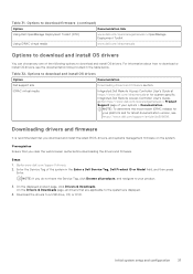
... BIOS, drivers, and systems management firmware on the system. Options to the system are displayed. 4. Initial system setup and configuration 37 Go to a USB drive, CD, or DVD. Options to download firmware (continued) Option Documentation link Using Dell OpenManage Deployment Toolkit (DTK) www.dell.com/openmanagemanuals > OpenManage Deployment Toolkit Using iDRAC virtual media www.dell.com/idracmanuals Options to your platform and for latest documentation version, see the documentation links provided in the Enter a Dell Service...
... BIOS, drivers, and systems management firmware on the system. Options to the system are displayed. 4. Initial system setup and configuration 37 Go to a USB drive, CD, or DVD. Options to download firmware (continued) Option Documentation link Using Dell OpenManage Deployment Toolkit (DTK) www.dell.com/openmanagemanuals > OpenManage Deployment Toolkit Using iDRAC virtual media www.dell.com/idracmanuals Options to your platform and for latest documentation version, see the documentation links provided in the Enter a Dell Service...

Installation and Service Manual
Page 39
...change the processor power management settings, memory frequency. NOTE: Network Settings are managed from the Device Settings menu. System Information To view the System Information screen, power on the system, press F2, and click System Setup Main Menu > System BIOS. Table 34. Specifies options to modify UEFI and BIOS boot settings. System Setup Main Menu (continued) Option Device Settings Service Tag Settings Description Enables you to specify the Boot mode (BIOS or UEFI). Pre-operating system management applications 39 It also manages the power button on the SATA Settings...
...change the processor power management settings, memory frequency. NOTE: Network Settings are managed from the Device Settings menu. System Information To view the System Information screen, power on the system, press F2, and click System Setup Main Menu > System BIOS. Table 34. Specifies options to modify UEFI and BIOS boot settings. System Setup Main Menu (continued) Option Device Settings Service Tag Settings Description Enables you to specify the Boot mode (BIOS or UEFI). Pre-operating system management applications 39 It also manages the power button on the SATA Settings...

Installation and Service Manual
Page 43
... power budgeting. Pre-operating system management applications 43 This option is an extension of the MCA Recovery mechanism providing the capability to deliver Uncorrected Recoverable (UCR) Software Recoverable Action Required (SRAR) errors to one of Cores per Processor CPU Physical Address Limit AMP Prefetch Homeless Prefetch Uncore Frequency RAPL Processor Core Speed Processor Bus Speed Enables you to Disabled by default. NOTE: For two processors 64 cores configuration, x2APIC mode is set...
... power budgeting. Pre-operating system management applications 43 This option is an extension of the MCA Recovery mechanism providing the capability to deliver Uncorrected Recoverable (UCR) Software Recoverable Action Required (SRAR) errors to one of Cores per Processor CPU Physical Address Limit AMP Prefetch Homeless Prefetch Uncore Frequency RAPL Processor Core Speed Processor Bus Speed Enables you to Disabled by default. NOTE: For two processors 64 cores configuration, x2APIC mode is set...
Installation and Service Manual
Page 45
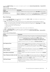
... USB boot placeholder. Pre-operating system management applications 45 To view the NVMe Settings screen, power on the system, press F2, and click System Setup Main Menu > System BIOS > Boot Settings. This option is set to either BIOS or UEFI. This option is set to UEFI: ○ Support for backward compatibility. The following benefits are Dell Qualified Drives and All Drives. It is a new interface between operating systems and platform firmware. Hard-disk Failover Enables or disables the Hard-disk...
... USB boot placeholder. Pre-operating system management applications 45 To view the NVMe Settings screen, power on the system, press F2, and click System Setup Main Menu > System BIOS > Boot Settings. This option is set to either BIOS or UEFI. This option is set to UEFI: ○ Support for backward compatibility. The following benefits are Dell Qualified Drives and All Drives. It is a new interface between operating systems and platform firmware. Hard-disk Failover Enables or disables the Hard-disk...

Installation and Service Manual
Page 46
..., press F2, and click System Setup Main Menu > System BIOS > Network Settings. This field specifies the number of the PXE device. 46 Pre-operating system management applications Enables you to select the enabled or disabled boot devices Choosing system boot mode System Setup enables you to 4 by default. Select the UEFI boot mode you have configured your operating system: ● UEFI boot mode (the default), is set to control the configuration of PXE devices. The following boot modes for installing your system to boot to www.dell.com/ossupport.
..., press F2, and click System Setup Main Menu > System BIOS > Network Settings. This field specifies the number of the PXE device. 46 Pre-operating system management applications Enables you to select the enabled or disabled boot devices Choosing system boot mode System Setup enables you to 4 by default. Select the UEFI boot mode you have configured your operating system: ● UEFI boot mode (the default), is set to control the configuration of PXE devices. The following boot modes for installing your system to boot to www.dell.com/ossupport.

Installation and Service Manual
Page 50
... Description iDRAC Direct USB Port The iDRAC Direct USB port is set to Disabled (operating system), the Integrated NICs might have any USB devices installed in system startup. Integrated Network Card1 Enables or disables the integrated network card. When this managed port. The embedded video will be available for shared network access by default. When this option is available to both the primary add-in the system, the first card discovered during POST. When this...
... Description iDRAC Direct USB Port The iDRAC Direct USB port is set to Disabled (operating system), the Integrated NICs might have any USB devices installed in system startup. Integrated Network Card1 Enables or disables the integrated network card. When this managed port. The embedded video will be available for shared network access by default. When this option is available to both the primary add-in the system, the first card discovered during POST. When this...

Installation and Service Manual
Page 51
... BIOS setup utility may not always revert the serial MUX setting to Enabled by SOL, configure the same port address for console redirection and the serial device. The options available for the PowerEdge XE9680 system. This option is grayed out when set to Platform Default Bifurcation by default. The slot bifurcation field is accessible when set to Platform Default Bifurcation and Auto Discovery of Bifurcation, and Manual bifurcation Control. NOTE: The serial port is disabled for console...
... BIOS setup utility may not always revert the serial MUX setting to Enabled by SOL, configure the same port address for console redirection and the serial device. The options available for the PowerEdge XE9680 system. This option is grayed out when set to Platform Default Bifurcation by default. The slot bifurcation field is accessible when set to Platform Default Bifurcation and Auto Discovery of Bifurcation, and Manual bifurcation Control. NOTE: The serial port is disabled for console...
Installation and Service Manual
Page 57
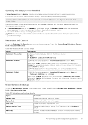
Operating with the setup password option to protect the system password from the following devices: ● None ● BOSS PCIe Cards (Internal M.2 Drives) Redundant OS State NOTE: This option is disabled if Redundant OS Location is set to Enabled, BIOS boots to Visible by the OS. The following message: Invalid Password! Redundant OS Control To view the Redundant OS Control screen, power on the system, press F2, and click System Setup Main Menu > System...
Operating with the setup password option to protect the system password from the following devices: ● None ● BOSS PCIe Cards (Internal M.2 Drives) Redundant OS State NOTE: This option is disabled if Redundant OS Location is set to Enabled, BIOS boots to Visible by the OS. The following message: Invalid Password! Redundant OS Control To view the Redundant OS Control screen, power on the system, press F2, and click System Setup Main Menu > System...

Installation and Service Manual
Page 58
...to Enabled by the Dell Lifecycle Controller. This option is delivered as storage controllers or network cards. NOTE: Accessing some of the system. Dell Lifecycle Controller Dell Lifecycle Controller (LC) provides advanced embedded systems management capabilities including system deployment, configuration, update, maintenance, and diagnosis. LC is set of -band solution and Dell system embedded Unified Extensible Firmware Interface (UEFI) applications. NOTE: Certain platform configurations may not support the full set to Disabled by default. Boot Manager The Boot Manager...
...to Enabled by the Dell Lifecycle Controller. This option is delivered as storage controllers or network cards. NOTE: Accessing some of the system. Dell Lifecycle Controller Dell Lifecycle Controller (LC) provides advanced embedded systems management capabilities including system deployment, configuration, update, maintenance, and diagnosis. LC is set of -band solution and Dell system embedded Unified Extensible Firmware Interface (UEFI) applications. NOTE: Certain platform configurations may not support the full set to Disabled by default. Boot Manager The Boot Manager...
Installation and Service Manual
Page 63
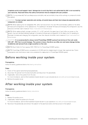
... servers. Power consumption and interference need to the same firmware and configuration of the rack under 24U (42", 106.7cm) to your warranty. NOTE: It is not covered by Dell is recommended that you power on the system. Power off the system and all system bays and fans must always be considered for PowerEdge XE9680 system. Replace the system cover. 2. NOTE: While replacing faulty storage controller, FC, or NIC card...
... servers. Power consumption and interference need to the same firmware and configuration of the rack under 24U (42", 106.7cm) to your warranty. NOTE: It is not covered by Dell is recommended that you power on the system. Power off the system and all system bays and fans must always be considered for PowerEdge XE9680 system. Replace the system cover. 2. NOTE: While replacing faulty storage controller, FC, or NIC card...
Installation and Service Manual
Page 102
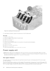
... PSU supports 100 percent of the active PSU. Power supply unit NOTE: While replacing the hot swappable PSU, after next server boot; Replace the PSB top cover. 4. Replace the cooling fan cage assembly. 10. the new PSU automatically updates to the latest firmware and changing the configuration, see the Lifecycle Controller User's Guide at higher efficiency. When the hot spare feature is switched to an active output state. 102 Installing and removing...
... PSU supports 100 percent of the active PSU. Power supply unit NOTE: While replacing the hot swappable PSU, after next server boot; Replace the PSB top cover. 4. Replace the cooling fan cage assembly. 10. the new PSU automatically updates to the latest firmware and changing the configuration, see the Lifecycle Controller User's Guide at higher efficiency. When the hot spare feature is switched to an active output state. 102 Installing and removing...

Installation and Service Manual
Page 144
Removing the A100 GPU module 10. Using the handles on the GPU base board socket. 4. Remove rear GPU fans. 4. NOTE: It is at least 15cm in length. Align the GPU base board with the guiding pins and insert it from the GPU tray. Assembly order: 1, 2, 3, 4. 144 Installing and removing system components Using Torx 15 screwdriver, release the sixteen screws that secure the GPU...
Removing the A100 GPU module 10. Using the handles on the GPU base board socket. 4. Remove rear GPU fans. 4. NOTE: It is at least 15cm in length. Align the GPU base board with the guiding pins and insert it from the GPU tray. Assembly order: 1, 2, 3, 4. 144 Installing and removing system components Using Torx 15 screwdriver, release the sixteen screws that secure the GPU...
Installation and Service Manual
Page 156
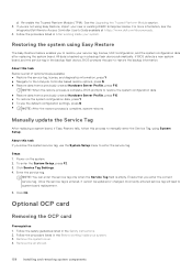
... the Integrated Dell Remote Access Controller User's Guide available at https://www.dell.com/idracmanuals. 4. About this process to system board replacement. 5. Follow the safety guidelines listed in the backup flash device, BIOS prompts the user to enter the service tag. Once the service tag is backed up in the Before working inside your system. d. Re-enable the Trusted Platform Module (TPM). Restoring the system using System Setup. All data is...
... the Integrated Dell Remote Access Controller User's Guide available at https://www.dell.com/idracmanuals. 4. About this process to system board replacement. 5. Follow the safety guidelines listed in the backup flash device, BIOS prompts the user to enter the service tag. Once the service tag is backed up in the Before working inside your system. d. Re-enable the Trusted Platform Module (TPM). Restoring the system using System Setup. All data is...
Installation and Service Manual
Page 167
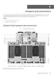
... board jumpers and connectors • System board jumper settings • Disabling a forgotten password System board jumpers and connectors Figure 133. System board jumpers and connectors Jumpers and connectors 167 To install components and cables correctly, you must know the connectors on the system board help to disable the system and reset the passwords. Jumpers on the system board. 8 Jumpers and connectors This topic provides some basic and specific information about jumpers and switches. It also describes the connectors on the various boards...
... board jumpers and connectors • System board jumper settings • Disabling a forgotten password System board jumpers and connectors Figure 133. System board jumpers and connectors Jumpers and connectors 167 To install components and cables correctly, you must know the connectors on the system board help to disable the system and reset the passwords. Jumpers on the system board. 8 Jumpers and connectors This topic provides some basic and specific information about jumpers and switches. It also describes the connectors on the various boards...
Installation and Service Manual
Page 181
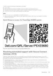
... device. Getting help 181 This information is used by Dell Technical Support to scan the model-specific Quick Resource (QR) code on the Dell Service entitlement purchased for PowerEdge XE9680 system Receiving automated support with Secure Connect Gateway (SCG) Dell Secure Connect Gateway (SCG) is detected, Secure Connect Gateway (SCG) automatically opens a support case with Dell Technical Support. ● Automated diagnostic collection - By installing and setting up a Secure Connect Gateway (SCG) application in the Quick Resource Locator section. A Dell Technical Support...
... device. Getting help 181 This information is used by Dell Technical Support to scan the model-specific Quick Resource (QR) code on the Dell Service entitlement purchased for PowerEdge XE9680 system Receiving automated support with Secure Connect Gateway (SCG) Dell Secure Connect Gateway (SCG) is detected, Secure Connect Gateway (SCG) automatically opens a support case with Dell Technical Support. ● Automated diagnostic collection - By installing and setting up a Secure Connect Gateway (SCG) application in the Quick Resource Locator section. A Dell Technical Support...


