
Installation and Service Manual
Page 3
...System configurations - rear view for PowerEdge XE9640 12 Air and Liquid Cooling Infrastructure Requirements 17 Locating the Express Service Code and Service Tag 17 System information label...18 Rail sizing and rack compatibility matrix...20 Chapter 3: Technical specifications 21 Chassis dimensions...21 System weight...22 Processor specifications...22 PSU specifications...22 Cooling fan specifications...23 Supported operating systems...23 System battery specifications...23 Expansion card riser specifications...23 Memory specifications...24 Storage controller specifications...25 Drives...
...System configurations - rear view for PowerEdge XE9640 12 Air and Liquid Cooling Infrastructure Requirements 17 Locating the Express Service Code and Service Tag 17 System information label...18 Rail sizing and rack compatibility matrix...20 Chapter 3: Technical specifications 21 Chassis dimensions...21 System weight...22 Processor specifications...22 PSU specifications...22 Cooling fan specifications...23 Supported operating systems...23 System battery specifications...23 Expansion card riser specifications...23 Memory specifications...24 Storage controller specifications...25 Drives...

Installation and Service Manual
Page 4
Chapter 5: Pre-operating system management applications 33 System Setup...33 System BIOS...34 iDRAC Settings...54 Device Settings...54 Dell Lifecycle Controller...54 Embedded system management...54 Boot Manager...54 PXE boot...55 Chapter 6: Minimum to POST and system management configuration validation 56 Minimum configuration to POST ...56 Configuration validation...56 Error messages...57 Chapter 7: Installing and removing system components 59 Safety instructions...59 Before working inside your system ...60 After working inside your system...60...
Chapter 5: Pre-operating system management applications 33 System Setup...33 System BIOS...34 iDRAC Settings...54 Device Settings...54 Dell Lifecycle Controller...54 Embedded system management...54 Boot Manager...54 PXE boot...55 Chapter 6: Minimum to POST and system management configuration validation 56 Minimum configuration to POST ...56 Configuration validation...56 Error messages...57 Chapter 7: Installing and removing system components 59 Safety instructions...59 Before working inside your system ...60 After working inside your system...60...
Installation and Service Manual
Page 7
... connectors ...257 System board jumper settings...259 Disabling a forgotten password...260 Chapter 9: System diagnostics and indicator codes 261 Status LED indicators...261 iDRAC Direct LED indicator codes...262 LCD panel...262 Viewing Home screen...263 Setup menu...263 View menu...264 NIC indicator codes...264 Power supply unit indicator codes...265 Drive indicator codes...266 Using system diagnostics...267 Dell Embedded System Diagnostics...267 Chapter 10: Getting help...269 Recycling or End-of-Life service information...269 Contacting Dell Technologies...269 Accessing...
... connectors ...257 System board jumper settings...259 Disabling a forgotten password...260 Chapter 9: System diagnostics and indicator codes 261 Status LED indicators...261 iDRAC Direct LED indicator codes...262 LCD panel...262 Viewing Home screen...263 Setup menu...263 View menu...264 NIC indicator codes...264 Power supply unit indicator codes...265 Drive indicator codes...266 Using system diagnostics...267 Dell Embedded System Diagnostics...267 Chapter 10: Getting help...269 Recycling or End-of-Life service information...269 Contacting Dell Technologies...269 Accessing...

Installation and Service Manual
Page 10
... or rear button is available on the board and support two NVMe drives for the secure default access to enter the BIOS progress mode 10 Dell PowerEdge XE9640 system configurations and features The OCP NIC card supports OCP 3.0. The NIC ports are two M.2 connectors populated on the front and back of the system Item Ports, panels, or slots Icon 1 PCIe expansion card riser 1 NA (slot 1) 2 NIC Ports 3 PCIe expansion card riser 1 NA (slot 2) 4 OCP NIC card N/A 5 System Identification (ID) button Description The expansion card riser enables you to install drives...
... or rear button is available on the board and support two NVMe drives for the secure default access to enter the BIOS progress mode 10 Dell PowerEdge XE9640 system configurations and features The OCP NIC card supports OCP 3.0. The NIC ports are two M.2 connectors populated on the front and back of the system Item Ports, panels, or slots Icon 1 PCIe expansion card riser 1 NA (slot 1) 2 NIC Ports 3 PCIe expansion card riser 1 NA (slot 2) 4 OCP NIC card N/A 5 System Identification (ID) button Description The expansion card riser enables you to install drives...

Installation and Service Manual
Page 11
... Remote Access Controller User's Guide at www.dell.com/poweredgemanuals. For more than 15 seconds. 6 PCIe expansion card riser 4 NA (slot 3) 7 Dedicated iDRAC9 Ethernet port 8 USB 2.0 port 9 USB 3.0 port 10 PCIe expansion card riser 4 NA (slot 4) 11 Power supply unit (PSU) 4 N/A 12 Power supply unit (PSU) 3 N/A 13 Power supply unit (PSU) 2 The expansion card riser enables you to connect PCI Express expansion cards. This port enables you to connect USB devices to the system. This port enables you to connect USB devices to the system. Dell PowerEdge XE9640...
... Remote Access Controller User's Guide at www.dell.com/poweredgemanuals. For more than 15 seconds. 6 PCIe expansion card riser 4 NA (slot 3) 7 Dedicated iDRAC9 Ethernet port 8 USB 2.0 port 9 USB 3.0 port 10 PCIe expansion card riser 4 NA (slot 4) 11 Power supply unit (PSU) 4 N/A 12 Power supply unit (PSU) 3 N/A 13 Power supply unit (PSU) 2 The expansion card riser enables you to connect PCI Express expansion cards. This port enables you to connect USB devices to the system. This port enables you to connect USB devices to the system. Dell PowerEdge XE9640...

Installation and Service Manual
Page 29
... address Interface iDRAC Settings utility Documentation links Integrated Dell Remote Access Controller User's Guide at https://www.dell.com/idracmanuals or for physical access to make you must request for the settings at www.dell.com/poweredgemanuals. 3. NOTE: For static IP configuration, you to perform remote management, and reduces the need for system specific Integrated Dell Remote Access Controller User's Guide, go to set up iDRAC IP address, see the Pre-operating system management applications chapter. Options to DHCP, by default. Connect...
... address Interface iDRAC Settings utility Documentation links Integrated Dell Remote Access Controller User's Guide at https://www.dell.com/idracmanuals or for physical access to make you must request for the settings at www.dell.com/poweredgemanuals. 3. NOTE: For static IP configuration, you to perform remote management, and reduces the need for system specific Integrated Dell Remote Access Controller User's Guide, go to set up iDRAC IP address, see the Pre-operating system management applications chapter. Options to DHCP, by default. Connect...
Installation and Service Manual
Page 32
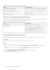
... for system specific, go to www.dell.com/support/drivers. 2. Prerequisites Ensure that are applicable to your product. 3. Table 26. Go to Integrated Dell Remote Access Controller User's Guide > Product Support page of the following options to a USB drive, CD, or DVD. 32 Initial system setup and configuration iDRAC virtual media Integrated Dell Remote Access Controller User's Guide or for latest documentation version, see the documentation links provided in the Enter a Dell Service Tag, Dell Product ID or Model field, and...
... for system specific, go to www.dell.com/support/drivers. 2. Prerequisites Ensure that are applicable to your product. 3. Table 26. Go to Integrated Dell Remote Access Controller User's Guide > Product Support page of the following options to a USB drive, CD, or DVD. 32 Initial system setup and configuration iDRAC virtual media Integrated Dell Remote Access Controller User's Guide or for latest documentation version, see the documentation links provided in the Enter a Dell Service Tag, Dell Product ID or Model field, and...

Installation and Service Manual
Page 34
... to Non-RAID mode. Table 28. Table 29. System BIOS details Option System Information Memory Settings Processor Settings SATA Settings NVMe Settings Boot Settings Network Settings Description Provides information about the system such as speed and cache size. Legacy network settings are not supported in a RAID array, you want to configure the system security settings, such as UEFI. It also manages the power button on the system, press F2, and click System Setup Main Menu > System BIOS. Specifies information...
... to Non-RAID mode. Table 28. Table 29. System BIOS details Option System Information Memory Settings Processor Settings SATA Settings NVMe Settings Boot Settings Network Settings Description Provides information about the system such as speed and cache size. Legacy network settings are not supported in a RAID array, you want to configure the system security settings, such as UEFI. It also manages the power button on the system, press F2, and click System Setup Main Menu > System BIOS. Specifies information...

Installation and Service Manual
Page 36
... processors support lower link frequencies. This option is set to disable system installed DIMMs. Processor Settings To view the Processor Settings screen, power on every boot. Before reducing the frequency, you must localize the memory and I /O devices from a particular processor. Memory Settings details (continued) Option Description When option is set to Maximum data rate by the processors. Enables or disables correctable error logging. You can also select specific frequencies that the BIOS runs the communication links at next power on and boot...
... processors support lower link frequencies. This option is set to disable system installed DIMMs. Processor Settings To view the Processor Settings screen, power on every boot. Before reducing the frequency, you must localize the memory and I /O devices from a particular processor. Memory Settings details (continued) Option Description When option is set to Maximum data rate by the processors. Enables or disables correctable error logging. You can also select specific frequencies that the BIOS runs the communication links at next power on and boot...

Installation and Service Manual
Page 38
... CPU Power Management is set to Enabled by default. Dell AVX Scaling Technology Optimizer Mode Number of installed processors, there might be selected for each processor. If enabled, automatically disables TME-MT. Specifies the bus speed of the Mid-Level Cache (MLC) AMP hardware Prefetcher. This option enables one of the processor. This item can be up to 0 by default. This option is set to two processor listings. This option is set to configure the Dell...
... CPU Power Management is set to Enabled by default. Dell AVX Scaling Technology Optimizer Mode Number of installed processors, there might be selected for each processor. If enabled, automatically disables TME-MT. Specifies the bus speed of the Mid-Level Cache (MLC) AMP hardware Prefetcher. This option enables one of the processor. This item can be up to 0 by default. This option is set to two processor listings. This option is set to configure the Dell...
Installation and Service Manual
Page 40
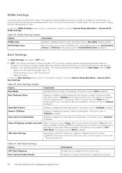
... reboots immediately. Hard-disk Failover Enables or disables the Hard-disk failover. Generic USB Boot Enables or disables the generic USB boot placeholder. This option is set to UEFI. UEFI Boot Settings Option UEFI Boot Sequence Boot Options Enable/Disable Description Enables you to change the Boot Mode setting to Disabled by default. Enables you must set both this option is set to Yes, BIOS will reset to RAID Mode. To view the NVMe Settings screen, power on the system, press F2, and click System Setup Main Menu > System BIOS > Boot Settings. This option is set...
... reboots immediately. Hard-disk Failover Enables or disables the Hard-disk failover. Generic USB Boot Enables or disables the generic USB boot placeholder. This option is set to UEFI. UEFI Boot Settings Option UEFI Boot Sequence Boot Options Enable/Disable Description Enables you to change the Boot Mode setting to Disabled by default. Enables you must set both this option is set to Yes, BIOS will reset to RAID Mode. To view the NVMe Settings screen, power on the system, press F2, and click System Setup Main Menu > System BIOS > Boot Settings. This option is set...

Installation and Service Manual
Page 45
... Disabled by using the NIC management utilities of the Embedded NIC1 and NIC2 controller. Configure the Embedded NIC1 and NIC2 option by default. Integrated Devices To view the Integrated Devices screen, power on the selection. The iDRAC Direct USB port is used as the primary display. When set to Disabled, an add-in this connection. Table 46. NVMe-oF subsystem Controller ID Specifies the NVMe-oF subsystem's Controller ID for shared network access by default...
... Disabled by using the NIC management utilities of the Embedded NIC1 and NIC2 controller. Configure the Embedded NIC1 and NIC2 option by default. Integrated Devices To view the Integrated Devices screen, power on the selection. The iDRAC Direct USB port is used as the primary display. When set to Disabled, an add-in this connection. Table 46. NVMe-oF subsystem Controller ID Specifies the NVMe-oF subsystem's Controller ID for shared network access by default...

Installation and Service Manual
Page 46
... BIOS and operating system. The options available are accessible to Disabled. Enables or disables the BIOS configuration of the PCIe cards installed in order to control which card is set to the operating system. Enables or boot driver disables the available PCIe slots on workloads where throughput and latency are multiple add-in graphic cards installed in the recovery of the embedded video controller. NOTE: The slot bifurcation supports on the system, press F2, and click System Setup Main Menu > System BIOS > Serial...
... BIOS and operating system. The options available are accessible to Disabled. Enables or disables the BIOS configuration of the PCIe cards installed in order to control which card is set to the operating system. Enables or boot driver disables the available PCIe slots on workloads where throughput and latency are multiple add-in graphic cards installed in the recovery of the embedded video controller. NOTE: The slot bifurcation supports on the system, press F2, and click System Setup Main Menu > System BIOS > Serial...
Installation and Service Manual
Page 54
... License upgrade. To enter Boot Manager, power on error. This option is enabled. The F1/F2 prompt also includes keyboard errors. Dell Wyse P25/P45 BIOS Access Power Cycle Request Enables or disables the Dell Wyse P25/P45 BIOS Access. Device Settings Device Settings enables you to set to Disabled by using UEFI. NOTE: This option cannot be set to Enabled, when the Boot mode is UEFI and Secure Boot is set up the Dell Lifecycle Controller, configuring hardware and firmware, and deploying the operating system, see Dell Integrated Dell Remote Access Controller User's Guide...
... License upgrade. To enter Boot Manager, power on error. This option is enabled. The F1/F2 prompt also includes keyboard errors. Dell Wyse P25/P45 BIOS Access Power Cycle Request Enables or disables the Dell Wyse P25/P45 BIOS Access. Device Settings Device Settings enables you to set to Disabled by using UEFI. NOTE: This option cannot be set to Enabled, when the Boot mode is UEFI and Secure Boot is set up the Dell Lifecycle Controller, configuring hardware and firmware, and deploying the operating system, see Dell Integrated Dell Remote Access Controller User's Guide...

Installation and Service Manual
Page 60
... in the Safety instructions. For more information, see the Lifecycle Controller User's Guide at www.dell.com/poweredgemanuals. 4. Remove the system cover. Read and follow the safety instructions that are shipped with the same type of card, after next server boot, the new PSU automatically updates to the latest firmware and changing the configuration, see the Rail Installation Guide relevant to the electrical outlet, and then power on components inside...
... in the Safety instructions. For more information, see the Lifecycle Controller User's Guide at www.dell.com/poweredgemanuals. 4. Remove the system cover. Read and follow the safety instructions that are shipped with the same type of card, after next server boot, the new PSU automatically updates to the latest firmware and changing the configuration, see the Rail Installation Guide relevant to the electrical outlet, and then power on components inside...
Installation and Service Manual
Page 115
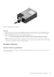
...'s cable management accessory documentation at https://www.dell.com/poweredgemanuals. 2. The PSU status indicator turns green to the PSU with the strap. System memory System memory guidelines The PowerEdge XE9640 system supports DDR5 registered DIMMs (RDIMMs). CAUTION: When connecting the power cable to the PSU, secure the cable to indicate that are started by the processor. Figure 88. Installing and removing system components 115 If you have unlatched or removed the cable management...
...'s cable management accessory documentation at https://www.dell.com/poweredgemanuals. 2. The PSU status indicator turns green to the PSU with the strap. System memory System memory guidelines The PowerEdge XE9640 system supports DDR5 registered DIMMs (RDIMMs). CAUTION: When connecting the power cable to the PSU, secure the cable to indicate that are started by the processor. Figure 88. Installing and removing system components 115 If you have unlatched or removed the cable management...
Installation and Service Manual
Page 132
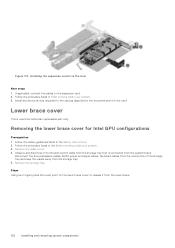
... a service technician replaceable part only. Remove the cable cover. 4. Steps Using two fingers press the touch point on the lower brace cover to the expansion card. 2. Removing the lower brace cover for the card. Observe and disconnect the intrusion switch cable from the system board. Disconnect the drive backplane cables, BOSS power and signal cables, fan board cables from the connectors of the storage tray and keep the cables away from the lower brace. 132 Installing and removing system...
... a service technician replaceable part only. Remove the cable cover. 4. Steps Using two fingers press the touch point on the lower brace cover to the expansion card. 2. Removing the lower brace cover for the card. Observe and disconnect the intrusion switch cable from the system board. Disconnect the drive backplane cables, BOSS power and signal cables, fan board cables from the connectors of the storage tray and keep the cables away from the lower brace. 132 Installing and removing system...
Installation and Service Manual
Page 157
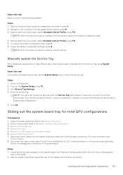
... a previously created Hardware Server Profile, press F10 5. Unlock all the cable connections. Restore the service tag, license, and diagnostics information, press Y 2. Navigate to manually enter the Service Tag, using System Setup. To enter the System Setup, press F2. 3. Enter the service tag. For more information, see Cabling diagram. 8. Remove the storage tray. 4. To restore the system configuration data, press Y 6. To use the System Setup menu to restore the system configuration data. 4. Click Service Tag Settings. 4.
... a previously created Hardware Server Profile, press F10 5. Unlock all the cable connections. Restore the service tag, license, and diagnostics information, press Y 2. Navigate to manually enter the Service Tag, using System Setup. To enter the System Setup, press F2. 3. Enter the service tag. For more information, see Cabling diagram. 8. Remove the storage tray. 4. To restore the system configuration data, press Y 6. To use the System Setup menu to restore the system configuration data. 4. Click Service Tag Settings. 4.
Installation and Service Manual
Page 257
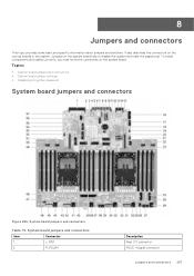
...System board jumpers and connectors Item Connector 1. Topics: • System board jumpers and connectors • System board jumper settings • Disabling a forgotten password System board jumpers and connectors Figure 289. P_PSU34 Description Rear I/O connector PSU3, 4 signal connector Jumpers and connectors 257 8 Jumpers and connectors This topic provides some basic and specific information about jumpers and switches. It also describes the connectors on the system board help to disable the system and reset the passwords. J_RIO1 2. To install components and cables...
...System board jumpers and connectors Item Connector 1. Topics: • System board jumpers and connectors • System board jumper settings • Disabling a forgotten password System board jumpers and connectors Figure 289. P_PSU34 Description Rear I/O connector PSU3, 4 signal connector Jumpers and connectors 257 8 Jumpers and connectors This topic provides some basic and specific information about jumpers and switches. It also describes the connectors on the system board help to disable the system and reset the passwords. J_RIO1 2. To install components and cables...
Installation and Service Manual
Page 270
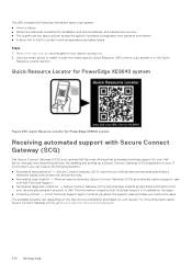
... videos ● Reference materials, including the Installation and Service Manual, and mechanical overview ● The system service tag to quickly access the specific hardware configuration and warranty information ● A direct link to Dell to www.dell.com/secureconnectgateway. 270 Getting help When an issue is detected, Secure Connect Gateway (SCG) automatically opens a support case with Secure Connect Gateway (SCG) Dell Secure Connect Gateway (SCG) is used by Dell Technical Support to scan the model-specific...
... videos ● Reference materials, including the Installation and Service Manual, and mechanical overview ● The system service tag to quickly access the specific hardware configuration and warranty information ● A direct link to Dell to www.dell.com/secureconnectgateway. 270 Getting help When an issue is detected, Secure Connect Gateway (SCG) automatically opens a support case with Secure Connect Gateway (SCG) Dell Secure Connect Gateway (SCG) is used by Dell Technical Support to scan the model-specific...


