
Glossary
Page 1
... processor to direct configuration and power management. BMC - It provides mapping techniques for interchange of a program or data file. Dell™ Glossary NOTE: For additional information on storage terminology, visit the Storage Networking Industry Association's website at www.snia.org ... A - Ampere(s). Advanced Configuration and Power Interface. backup - blade - Baseboard management controller. A CD, diskette, or USB memory key that is located. Your system contains an expansion bus that contains a processor, memory, and a hard drive. Certificate authority.
... processor to direct configuration and power management. BMC - It provides mapping techniques for interchange of a program or data file. Dell™ Glossary NOTE: For additional information on storage terminology, visit the Storage Networking Industry Association's website at www.snia.org ... A - Ampere(s). Advanced Configuration and Power Interface. backup - blade - Baseboard management controller. A CD, diskette, or USB memory key that is located. Your system contains an expansion bus that contains a processor, memory, and a hard drive. Certificate authority.

Glossary
Page 5
...system used for implementing shared storage on a network. However, when referring to hard-drive capacity, the term is monitored and managed using Dell OpenManage™ Server Administrator. MBps - memory module - memory key - mirroring - NAS systems have their own operating systems, integrated ...-in the system's RAM. Megahertz. NAS - Megabits per second. Master boot record. A portable flash memory storage device integrated with a USB connector. Mirroring functionality is an ASCII file that are optimized to mean 1,000,000 bytes. MOF - A managed system is one of ...
...system used for implementing shared storage on a network. However, when referring to hard-drive capacity, the term is monitored and managed using Dell OpenManage™ Server Administrator. MBps - memory module - memory key - mirroring - NAS systems have their own operating systems, integrated ...-in the system's RAM. Megahertz. NAS - Megabits per second. Master boot record. A portable flash memory storage device integrated with a USB connector. Mirroring functionality is an ASCII file that are optimized to mean 1,000,000 bytes. MOF - A managed system is one of ...

Glossary
Page 8
... the system should be configured for the devices. Some devices (such as password protection. An unregistered (unbuffered) DDR3 memory module. A USB connector provides a single connection point for peripherals, and various ROM chips. Used to describe a system that allows you to enable or... Protocol. When such devices are video standards for video adapters with greater resolution and color display capabilities than previous standards. TOE - USB memory key - USB - See memory key. 8 SMP - Symmetric multiprocessing. A virtual disk may need to configure your system in the event of ...
... the system should be configured for the devices. Some devices (such as password protection. An unregistered (unbuffered) DDR3 memory module. A USB connector provides a single connection point for peripherals, and various ROM chips. Used to describe a system that allows you to enable or... Protocol. When such devices are video standards for video adapters with greater resolution and color display capabilities than previous standards. TOE - USB memory key - USB - See memory key. 8 SMP - Symmetric multiprocessing. A virtual disk may need to configure your system in the event of ...
Glossary
Page 15
Windows Management Instrumentation 提供 CIM ZIF CPU I/O 9 USB 15 TCP/IP U-DIMM DDR3 UPS USB USB USB USB USB V VAC VDC VGA VGA 和 SVGA W WH WMI - SNMP SVGA VGA 和 SVGA TCP/IP Internet 协议。 TOE -
Windows Management Instrumentation 提供 CIM ZIF CPU I/O 9 USB 15 TCP/IP U-DIMM DDR3 UPS USB USB USB USB USB V VAC VDC VGA VGA 和 SVGA W WH WMI - SNMP SVGA VGA 和 SVGA TCP/IP Internet 协议。 TOE -

Glossary
Page 48
Video graphics array VGA と SVGA W - Simple Network Management Protocol SVGA - Universal Serial Bus USB USB USB USB V - Volt direct current VGA - Uninterruptible power supply USB - Volt VAC - Super video graphics array VGA と SVGA TCP/IP - Volts alternating current VDC - Watt-hour WMI - Zero insertion force 48 Unregistered DDR3 UPS - ...
Video graphics array VGA と SVGA W - Simple Network Management Protocol SVGA - Universal Serial Bus USB USB USB USB V - Volt direct current VGA - Uninterruptible power supply USB - Volt VAC - Super video graphics array VGA と SVGA TCP/IP - Volts alternating current VDC - Watt-hour WMI - Zero insertion force 48 Unregistered DDR3 UPS - ...

Glossary
Page 58
.../IP Transmission Control Protocol/Internet Protocol TOE - TCP/IP TCP/IP Offload Engine U-DIMM DDR3 Unregistered(Unbuffered) DDR3 Memory Module UPS Uninterruptible Power Supply USB Universal Serial Bus USB USB USB USB V - 볼트 (Volt VAC Volt Alternating Current VDC Volt Direct Current VGA Video Graphics Array VGA 와 SVGA W - 와트 (Watt WH Watt...
.../IP Transmission Control Protocol/Internet Protocol TOE - TCP/IP TCP/IP Offload Engine U-DIMM DDR3 Unregistered(Unbuffered) DDR3 Memory Module UPS Uninterruptible Power Supply USB Universal Serial Bus USB USB USB USB V - 볼트 (Volt VAC Volt Alternating Current VDC Volt Direct Current VGA Video Graphics Array VGA 와 SVGA W - 와트 (Watt WH Watt...
Dell PowerEdge Deployment Guide
Page 4
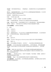
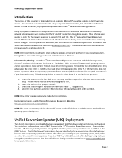
...4. Older versions of the Microsoft operating systems are attached during operating system deployment. The controller is delivered as flash drives or USB drives are not supported on the partition. Select the new partition and press to install the operating system on these servers. ...see the Microsoft Knowledge Base article 896536 on deploying Microsoft® operating systems to Dell PowerEdge servers. This can result in the partition selection part of text-mode setup. PowerEdge Deployment Guide Introduction The purpose of this document is to provide tips on http://...
...4. Older versions of the Microsoft operating systems are attached during operating system deployment. The controller is delivered as flash drives or USB drives are not supported on the partition. Select the new partition and press to install the operating system on these servers. ...see the Microsoft Knowledge Base article 896536 on deploying Microsoft® operating systems to Dell PowerEdge servers. This can result in the partition selection part of text-mode setup. PowerEdge Deployment Guide Introduction The purpose of this document is to provide tips on http://...
Dell PowerEdge Deployment Guide
Page 6
...be installed after the operating system installation is added per the Microsoft WDS / RIS documentation. For the 11th Generation PowerEdge servers, you are installed. Dell recommends that the mass storage driver for the mass storage drivers. This will also need to install the chipset, ...for the Broadcom NetXtreme 5708 and 5709 adapters. System will also need to add the network adapter driver. To assist, Dell developed the Dell USB Key F6 Driver Utility. See Microsoft Knowledge Base article 315279 on http://support.microsoft.com/kb/254078/en. Microsoft Automated ...
...be installed after the operating system installation is added per the Microsoft WDS / RIS documentation. For the 11th Generation PowerEdge servers, you are installed. Dell recommends that the mass storage driver for the mass storage drivers. This will also need to install the chipset, ...for the Broadcom NetXtreme 5708 and 5709 adapters. System will also need to add the network adapter driver. To assist, Dell developed the Dell USB Key F6 Driver Utility. See Microsoft Knowledge Base article 315279 on http://support.microsoft.com/kb/254078/en. Microsoft Automated ...
Deploying UEFI-Aware Operating Systems on Dell PowerEdge Servers
Page 5
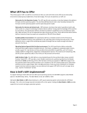
...between the platform firmware and the operating system. The list of supported bus types may provide enhanced platform capabilities, such as standard bus types (PCI, USB, and SCSI). The UEFI specification defines extensible interfaces that has been common to computers. The UEFI defines a new standard layout for devices and related... of UEFI are components of the pre‐boot environment. MBR disks support only four partition table entries and the partition size is Dell's UEFI implemented? Setting the Boot Mode to both UEFI and non‐UEFI aware operating systems, the...
...between the platform firmware and the operating system. The list of supported bus types may provide enhanced platform capabilities, such as standard bus types (PCI, USB, and SCSI). The UEFI specification defines extensible interfaces that has been common to computers. The UEFI defines a new standard layout for devices and related... of UEFI are components of the pre‐boot environment. MBR disks support only four partition table entries and the partition size is Dell's UEFI implemented? Setting the Boot Mode to both UEFI and non‐UEFI aware operating systems, the...
Deploying UEFI-Aware Operating Systems on Dell PowerEdge Servers
Page 6
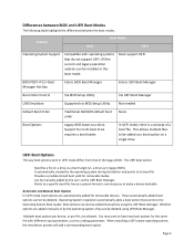
...a drive as a boot option on a single drive. Is automatically created by the user via BIOS Setup Utility Not needed Default Boot Order Traditional Dell BIOS default boot order None Boot Options Legacy BIOS boots to its boot file. Provides a predetermined boot path for multi‐boot drive requires a... Boot Manager Hot Key Enters BIOS Boot Manager Enters UEFI Boot Manager Boot Order Control Via BIOS Setup Utility Via UEFI Boot Manager USB Emulation Supported via the UEFI Boot Manager. Multiple boot options per device, or per file, are automatically added for the same file...
...a drive as a boot option on a single drive. Is automatically created by the user via BIOS Setup Utility Not needed Default Boot Order Traditional Dell BIOS default boot order None Boot Options Legacy BIOS boots to its boot file. Provides a predetermined boot path for multi‐boot drive requires a... Boot Manager Hot Key Enters BIOS Boot Manager Enters UEFI Boot Manager Boot Order Control Via BIOS Setup Utility Via UEFI Boot Manager USB Emulation Supported via the UEFI Boot Manager. Multiple boot options per device, or per file, are automatically added for the same file...
Deploying UEFI-Aware Operating Systems on Dell PowerEdge Servers
Page 7
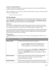
... in an optical drive), an error message displays along with a FAT32 file system, a menu displays to navigate to a file to select as a USB key, is detected in the \EFI\BOOT directory. Provides a menu of the device. the Optional Data is automatically added to point to the following ...and operating system installed and can be selected. When the Boot Mode is set to UEFI the BIOS Setup Utility fields, Boot Sequence and USB Flash Drive Emulation Type are available from this menu: Option Description Add Boot Option Provides a menu from which removes them from the front ...
... in an optical drive), an error message displays along with a FAT32 file system, a menu displays to navigate to a file to select as a USB key, is detected in the \EFI\BOOT directory. Provides a menu of the device. the Optional Data is automatically added to point to the following ...and operating system installed and can be selected. When the Boot Mode is set to UEFI the BIOS Setup Utility fields, Boot Sequence and USB Flash Drive Emulation Type are available from this menu: Option Description Add Boot Option Provides a menu from which removes them from the front ...

Getting Started Guide
Page 11
... secure digital (SD) module Up to sixteen 2.5-inch, hot-swap SAS/SATA/SSD internal drives or up to two optional external USB DVD-ROM or internal DVD-ROM (SATA) or DVD+RW (SATA) NOTE: DVD devices are data only. One 5.25-inch half-height tape backup device ...Four RJ-45 (for integrated 1-GB NICs) 9-pin, DTE, 16550-compatible Six 4-pin, USB 2.0-compliant 15-pin VGA Two 4-pin, USB 2.0-compliant One 4-pin, USB 2.0-compliant One optional flash memory card slot on internal SD module Getting Started With Your System 9 External optional...
... secure digital (SD) module Up to sixteen 2.5-inch, hot-swap SAS/SATA/SSD internal drives or up to two optional external USB DVD-ROM or internal DVD-ROM (SATA) or DVD+RW (SATA) NOTE: DVD devices are data only. One 5.25-inch half-height tape backup device ...Four RJ-45 (for integrated 1-GB NICs) 9-pin, DTE, 16550-compatible Six 4-pin, USB 2.0-compliant 15-pin VGA Two 4-pin, USB 2.0-compliant One 4-pin, USB 2.0-compliant One optional flash memory card slot on internal SD module Getting Started With Your System 9 External optional...

Hardware Owner's Manual
Page 6
... the Internal SD Module 121 Internal SD Flash Card 122 Installing an Internal SD Flash Card 122 Removing an Internal SD Flash Card 122 Internal USB Memory Key 123 NIC Hardware Key 125 6 Contents
... the Internal SD Module 121 Internal SD Flash Card 122 Installing an Internal SD Flash Card 122 Removing an Internal SD Flash Card 122 Internal USB Memory Key 123 NIC Hardware Key 125 6 Contents

Hardware Owner's Manual
Page 8
... System 159 Safety First - For You and Your System 159 Troubleshooting System Startup Failure 159 Troubleshooting External Connections 159 Troubleshooting the Video Subsystem 160 Troubleshooting a USB Device 160 Troubleshooting a Serial I/O Device 161 Troubleshooting a NIC 161 Troubleshooting a Wet System 162 Troubleshooting a Damaged System 164 Troubleshooting the System Battery 165 8 Contents...
... System 159 Safety First - For You and Your System 159 Troubleshooting System Startup Failure 159 Troubleshooting External Connections 159 Troubleshooting the Video Subsystem 160 Troubleshooting a USB Device 160 Troubleshooting a Serial I/O Device 161 Troubleshooting a NIC 161 Troubleshooting a Wet System 162 Troubleshooting a Damaged System 164 Troubleshooting the System Battery 165 8 Contents...

Hardware Owner's Manual
Page 9
Troubleshooting Power Supplies 165 Troubleshooting System Cooling Problems 166 Troubleshooting a Fan 166 Troubleshooting System Memory 167 Troubleshooting an Internal SD Card 169 Troubleshooting an Internal USB Memory Key . . . . . 170 Troubleshooting an Optical Drive 171 Troubleshooting a Tape Backup Unit 171 Troubleshooting an External Tape Drive 172 Troubleshooting a Hard Drive 174 Troubleshooting a Storage ...
Troubleshooting Power Supplies 165 Troubleshooting System Cooling Problems 166 Troubleshooting a Fan 166 Troubleshooting System Memory 167 Troubleshooting an Internal SD Card 169 Troubleshooting an Internal USB Memory Key . . . . . 170 Troubleshooting an Optical Drive 171 Troubleshooting a Tape Backup Unit 171 Troubleshooting an External Tape Drive 172 Troubleshooting a Hard Drive 174 Troubleshooting a Storage ...

Hardware Owner's Manual
Page 12
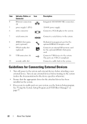
Front Panel Features and Indicators 7 6 5 4 3 2 1 8 9 10 Item Indicator, Button, or Icon Connector 1 Front bezel 2 USB connectors (2) 3 NMI button Description Covers the system's front-loading hard drives. Connects USB devices to troubleshoot software and device driver errors when using certain operating systems. This button can be pressed using the end of a paper clip... only if directed to do so by qualified support personnel or by the operating system's documentation. 12 About Your System The ports are USB 2.0-compliant. Front-Panel Features and Indicators Figure 1-1.
Front Panel Features and Indicators 7 6 5 4 3 2 1 8 9 10 Item Indicator, Button, or Icon Connector 1 Front bezel 2 USB connectors (2) 3 NMI button Description Covers the system's front-loading hard drives. Connects USB devices to troubleshoot software and device driver errors when using certain operating systems. This button can be pressed using the end of a paper clip... only if directed to do so by qualified support personnel or by the operating system's documentation. 12 About Your System The ports are USB 2.0-compliant. Front-Panel Features and Indicators Figure 1-1.
Hardware Owner's Manual
Page 22
...• Turn off power to enable ports on page 57. 22 About Your System The ports are USB 2.0-compliant. Guidelines for the optional iDRAC6 Enterprise card. Connects USB devices to the system. Turn on any external devices before attaching a new external device. Connects a ...the system. 7 serial connector Connects a serial device to the system. 8 iDRAC6 Enterprise port (optional) 9 VFlash media slot (optional) 10 USB connectors (6) 11 security cable slot Dedicated management port for the attached device has been installed on the system. • If necessary to the system...
...• Turn off power to enable ports on page 57. 22 About Your System The ports are USB 2.0-compliant. Guidelines for the optional iDRAC6 Enterprise card. Connects USB devices to the system. Turn on any external devices before attaching a new external device. Connects a ...the system. 7 serial connector Connects a serial device to the system. 8 iDRAC6 Enterprise port (optional) 9 VFlash media slot (optional) 10 USB connectors (6) 11 security cable slot Dedicated management port for the attached device has been installed on the system. • If necessary to the system...

Hardware Owner's Manual
Page 32
... Causes Corrective Actions E1810 Hard drive ## The specified hard drive fault. E1A15 SAS cable B SAS cable B is missing or Reseat the cable. USB cable to the control panel is bad. problem persists, replace connection. cable. E1920 iDRAC6 Upgrade The iDRAC6 Express card If the problem persists, Failed... See "Installing Memory Modules" on page 104 or "Troubleshooting System Memory" on page 174. problem persists, replace connection. E1A1D Control panel USB cable not detected. Check cable. Inspect DIMMs. Install or reseat memory modules. If the failure.
... Causes Corrective Actions E1810 Hard drive ## The specified hard drive fault. E1A15 SAS cable B SAS cable B is missing or Reseat the cable. USB cable to the control panel is bad. problem persists, replace connection. cable. E1920 iDRAC6 Upgrade The iDRAC6 Express card If the problem persists, Failed... See "Installing Memory Modules" on page 104 or "Troubleshooting System Memory" on page 174. problem persists, replace connection. E1A1D Control panel USB cable not detected. Check cable. Inspect DIMMs. Install or reseat memory modules. If the failure.

Hardware Owner's Manual
Page 44
... mouse or keyboard is set Check the system NICy: in the dedicated slot. 44 About Your System Reseat the mouse or keyboard cable. See "Troubleshooting a USB Device" on page 98. See "Getting Help" on faulty system board. page 193. An invalid system configuration caused a system halt.
... mouse or keyboard is set Check the system NICy: in the dedicated slot. 44 About Your System Reseat the mouse or keyboard cable. See "Troubleshooting a USB Device" on page 98. See "Getting Help" on faulty system board. page 193. An invalid system configuration caused a system halt.

Hardware Owner's Manual
Page 45
If operating locally, power cycle the system and enter system setup program to enable the USB port(s). The USB ports are disabled. See "General Memory Module Installation Guidelines" on page 58. Local keyboard may be reduced Invalid memory ...mode. The following DIMM has been disabled: x Invalid memory configuration. Memory Initialization Warning: Memory size may not work because all user accessible USB ports are disabled in a will run but with less memory valid configuration. Manufacturing mode detected System is physically available. The system will run ...
If operating locally, power cycle the system and enter system setup program to enable the USB port(s). The USB ports are disabled. See "General Memory Module Installation Guidelines" on page 58. Local keyboard may be reduced Invalid memory ...mode. The following DIMM has been disabled: x Invalid memory configuration. Memory Initialization Warning: Memory size may not work because all user accessible USB ports are disabled in a will run but with less memory valid configuration. Manufacturing mode detected System is physically available. The system will run ...


