
User Manual
Page 5
The power indicator should light. Installing the Bezel Install the bezel (optional). 5 Press the power button on the system. Installing The Optional Bezel Figure 5. Plug the other end of the power cable(s) into a grounded electrical outlet or a separate power source such as an uninterruptible power supply (UPS) or a power distribution unit (PDU). Turning On The System Figure 4. Turning On The System Remove the optional bezel, if installed.
The power indicator should light. Installing the Bezel Install the bezel (optional). 5 Press the power button on the system. Installing The Optional Bezel Figure 5. Plug the other end of the power cable(s) into a grounded electrical outlet or a separate power source such as an uninterruptible power supply (UPS) or a power distribution unit (PDU). Turning On The System Figure 4. Turning On The System Remove the optional bezel, if installed.

User Manual
Page 7
... official Mexican standards (NOM): Importer: Dell Inc. NOM Information The following specifications are only those required by law to support.dell.com. de México, S.A. Paseo de la Reforma 2620 -11º Piso Col. certification. Power AC Power Supply (per power supply) Wattage 495 W, 750 W, or... 1100 W Heat dissipation 1908 BTU/hr maximum (495 W power NOTE: Heat dissipation is provided...
... official Mexican standards (NOM): Importer: Dell Inc. NOM Information The following specifications are only those required by law to support.dell.com. de México, S.A. Paseo de la Reforma 2620 -11º Piso Col. certification. Power AC Power Supply (per power supply) Wattage 495 W, 750 W, or... 1100 W Heat dissipation 1908 BTU/hr maximum (495 W power NOTE: Heat dissipation is provided...

User Manual
Page 8
...-240 V AC, autoranging, 50/60 Hz NOTE: This system is calculated using the power supply wattage rating. Temperature 8 Voltage Battery Coin-cell battery -(48-60) V DC 3 V CR2032 Lithium coin cell Physical Height Width Depth Weight ... bezel 714.1 mm (28.1 inch) with a phase to IT power systems with bezel 46.0 kg (101.41 lb) Environmental NOTE: For additional information about environmental measurements for specific system configurations, see dell.com/environmental_datasheets. DC Power Supply (per power supply) (when available) Wattage 1100 W Heat dissipation 4416 BTU/hour maximum...
...-240 V AC, autoranging, 50/60 Hz NOTE: This system is calculated using the power supply wattage rating. Temperature 8 Voltage Battery Coin-cell battery -(48-60) V DC 3 V CR2032 Lithium coin cell Physical Height Width Depth Weight ... bezel 714.1 mm (28.1 inch) with a phase to IT power systems with bezel 46.0 kg (101.41 lb) Environmental NOTE: For additional information about environmental measurements for specific system configurations, see dell.com/environmental_datasheets. DC Power Supply (per power supply) (when available) Wattage 1100 W Heat dissipation 4416 BTU/hour maximum...

Owner's Manual
Page 5
... Card...69 Processors...70 Removing A Processor...70 Installing A Processor...73 Power Supplies...74 Hot Spare Feature...75 Removing An AC Power Supply...75 Installing An AC Power Supply...76 Wiring Instructions For A DC Power Supply...77 Removing A DC Power Supply...79 Installing A DC Power Supply...80 Removing The Power Supply Blank...81 Installing The Power Supply Blank...81 System Battery...81 Replacing The System Battery...81...
... Card...69 Processors...70 Removing A Processor...70 Installing A Processor...73 Power Supplies...74 Hot Spare Feature...75 Removing An AC Power Supply...75 Installing An AC Power Supply...76 Wiring Instructions For A DC Power Supply...77 Removing A DC Power Supply...79 Installing A DC Power Supply...80 Removing The Power Supply Blank...81 Installing The Power Supply Blank...81 System Battery...81 Replacing The System Battery...81...

Owner's Manual
Page 6
... Troubleshooting A USB Device...115 Troubleshooting A Serial I/O Device...116 Troubleshooting A NIC...116 Troubleshooting A Wet System...116 Troubleshooting A Damaged System...117 Troubleshooting The System Battery...118 Troubleshooting Power Supplies...118 Troubleshooting Cooling Problems...118 Troubleshooting Cooling Fans...119 Troubleshooting System Memory...119 Troubleshooting An Internal USB Key...120 Troubleshooting An SD Card...120 Troubleshooting...
... Troubleshooting A USB Device...115 Troubleshooting A Serial I/O Device...116 Troubleshooting A NIC...116 Troubleshooting A Wet System...116 Troubleshooting A Damaged System...117 Troubleshooting The System Battery...118 Troubleshooting Power Supplies...118 Troubleshooting Cooling Problems...118 Troubleshooting Cooling Fans...119 Troubleshooting System Memory...119 Troubleshooting An Internal USB Key...120 Troubleshooting An SD Card...120 Troubleshooting...

Owner's Manual
Page 10
The power button controls the power supply output to insert a vFlash media card. 3 Power-on indicator, power button The power-on indicator lights when the system power is on. Front-Panel Features and Indicators-3.5 Inch Hard-Drive Chassis Item Indicator, Button, or Icon Description Connector 1 Optical drive (optional) One optional SATA DVD-ROM drive or DVD+/-RW drive. 2 vFlash media card slot Allows you to the system. 10 Figure 2.
The power button controls the power supply output to insert a vFlash media card. 3 Power-on indicator, power button The power-on indicator lights when the system power is on. Front-Panel Features and Indicators-3.5 Inch Hard-Drive Chassis Item Indicator, Button, or Icon Description Connector 1 Optical drive (optional) One optional SATA DVD-ROM drive or DVD+/-RW drive. 2 vFlash media card slot Allows you to the system. 10 Figure 2.
Owner's Manual
Page 13
...BIOS progress mode. Allows you to record system information such as Service Tag, NIC, MAC address, and so on and off . The power button controls the power supply output to insert a vFlash media card. Use this button only if directed to do not support any hard drives and are installed with ...hard-drive blanks. 4 LCD panel 5 LCD menu buttons 6 vFlash media card slot 7 Power-on . To reset iDRAC (if not disabled in F2 iDRAC setup)...
...BIOS progress mode. Allows you to record system information such as Service Tag, NIC, MAC address, and so on and off . The power button controls the power supply output to insert a vFlash media card. Use this button only if directed to do not support any hard drives and are installed with ...hard-drive blanks. 4 LCD panel 5 LCD menu buttons 6 vFlash media card slot 7 Power-on . To reset iDRAC (if not disabled in F2 iDRAC setup)...

Owner's Manual
Page 18
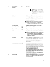
... Connector 4 System identification button The identification buttons on the front and back panels can be used to toggle the system ID on your system. 7 Power supply (PSU1) AC 495 W, 750 W, or 1100 W or DC 1100 W (when available) 8 USB connectors (6) 9 Video connector Allows you to... 2.0-compliant. Allows you to connect a VGA display to the system. 10 Serial connector Allows you to connect a serial device to the system. 11 Power supply (PSU2) 12 PCIe expansion card slots full height (3) (processor 2) AC 495 W, 750 W, or 1100 W or DC 1100 W (when available)...
... Connector 4 System identification button The identification buttons on the front and back panels can be used to toggle the system ID on your system. 7 Power supply (PSU1) AC 495 W, 750 W, or 1100 W or DC 1100 W (when available) 8 USB connectors (6) 9 Video connector Allows you to... 2.0-compliant. Allows you to connect a VGA display to the system. 10 Serial connector Allows you to connect a serial device to the system. 11 Power supply (PSU2) 12 PCIe expansion card slots full height (3) (processor 2) AC 495 W, 750 W, or 1100 W or DC 1100 W (when available)...

Owner's Manual
Page 19
... at less than its maximum port speed (1 Gbps or 10 Gbps). Figure 8. Power Indicator Codes Each AC power supply has an illuminated translucent handle and each DC power supply (when available) has an LED that serves as an indicator to show whether power is not connected to a valid network at its maximum port speed. Link indicator...
... at less than its maximum port speed (1 Gbps or 10 Gbps). Figure 8. Power Indicator Codes Each AC power supply has an illuminated translucent handle and each DC power supply (when available) has an LED that serves as an indicator to show whether power is not connected to a valid network at its maximum port speed. Link indicator...

Owner's Manual
Page 20
..., and supported voltage). Warranty information may be of the other power supply (in an error condition and unexpected system shutdown. DC Power Supply Status Indicator 1. CAUTION: When correcting a power supply mismatch, replace only the power supply with your system. Replace the power supply that has the flashing indicator with a power supply that the power supply is not supported and triggers a mismatch. The handle/LED...
..., and supported voltage). Warranty information may be of the other power supply (in an error condition and unexpected system shutdown. DC Power Supply Status Indicator 1. CAUTION: When correcting a power supply mismatch, replace only the power supply with your system. Replace the power supply that has the flashing indicator with a power supply that the power supply is not supported and triggers a mismatch. The handle/LED...

Owner's Manual
Page 37
... • #2 Phillips screwdriver • T10 and T15 Torx screwdrivers • Wrist grounding strap connected to ground Following tools are required for assembling cables for a DC power supply unit (PSU), when available: • AMP 90871-1 hand-crimping tool or equivalent • Wire-stripper pliers capable of the bezel into the chassis until the...
... • #2 Phillips screwdriver • T10 and T15 Torx screwdrivers • Wrist grounding strap connected to ground Following tools are required for assembling cables for a DC power supply unit (PSU), when available: • AMP 90871-1 hand-crimping tool or equivalent • Wire-stripper pliers capable of the bezel into the chassis until the...

Owner's Manual
Page 63
... installed to its side. 3. If applicable, disconnect the data cables for the PERC card or/and the power cables from the electrical outlet and peripherals. 2. Place the system upright. 12. Turn off the system, ...H710, H710P, and H810. • A system with six fan configuration. - NOTE: When you have the 1100 W power supply. Read and follow the safety instructions that support one 5.25 inch removable media storage devices. - Reconnect the system to ... the PCIe card holder. 10. On systems that is not authorized by Dell is not covered by a certified service technician.
... installed to its side. 3. If applicable, disconnect the data cables for the PERC card or/and the power cables from the electrical outlet and peripherals. 2. Place the system upright. 12. Turn off the system, ...H710, H710P, and H810. • A system with six fan configuration. - NOTE: When you have the 1100 W power supply. Read and follow the safety instructions that support one 5.25 inch removable media storage devices. - Reconnect the system to ... the PCIe card holder. 10. On systems that is not authorized by Dell is not covered by a certified service technician.

Owner's Manual
Page 74
.... Press to the system equally from 9. In redundant mode, power is supplied to enter the System Setup and check that the new processor operates correctly. and release the lever from both power supplies to the locked position. a) Identify the pin-1 corner of...down and out from the locked position. Power Supplies Your system supports either: • Two 495 W, 750 W, or 1100 W AC power supply modules or • Two 1100 W DC power supply modules (when available) When two identical power supplies are installed, the power supply configuration is seated. Locate the processor socket...
.... Press to the system equally from 9. In redundant mode, power is supplied to enter the System Setup and check that the new processor operates correctly. and release the lever from both power supplies to the locked position. a) Identify the pin-1 corner of...down and out from the locked position. Power Supplies Your system supports either: • Two 495 W, 750 W, or 1100 W AC power supply modules or • Two 1100 W DC power supply modules (when available) When two identical power supplies are installed, the power supply configuration is seated. Locate the processor socket...

Owner's Manual
Page 75
... sleep state monitors output voltage of the active power supply. Damage due to a sleep state. On power-redundant systems, remove and replace only one power supply at support.dell.com/manuals. Disconnect the power cable from the power source and the power supply you intend to an active output state. The redundant power supply in your warranty. For information about the cable...
... sleep state monitors output voltage of the active power supply. Damage due to a sleep state. On power-redundant systems, remove and replace only one power supply at support.dell.com/manuals. Disconnect the power cable from the power source and the power supply you intend to an active output state. The redundant power supply in your warranty. For information about the cable...

Owner's Manual
Page 76
... as authorized in Watts) is fully seated and the release latch snaps into a power outlet. Connect the power cable to servicing that the power supply is not covered by Dell is functioning properly. 76 The power-supply status indicator turns green to recognize the power supply and determine its status. connector 2. release latch 4. For information about the cable management...
... as authorized in Watts) is fully seated and the release latch snaps into a power outlet. Connect the power cable to servicing that the power supply is not covered by Dell is functioning properly. 76 The power-supply status indicator turns green to recognize the power supply and determine its status. connector 2. release latch 4. For information about the cable management...

Owner's Manual
Page 77
... that is not covered by Dell is suitably approved and rated shall be incorporated in the field wiring. Do not attempt connecting to servicing that came with a yellow stripe, stranded wire (safety ground) Assembling And Connecting The Safety Ground Wire WARNING: For equipment using -(48-60) V DC power supplies, a qualified electrician must perform...
... that is not covered by Dell is suitably approved and rated shall be incorporated in the field wiring. Do not attempt connecting to servicing that came with a yellow stripe, stranded wire (safety ground) Assembling And Connecting The Safety Ground Wire WARNING: For equipment using -(48-60) V DC power supplies, a qualified electrician must perform...

Owner's Manual
Page 78
3. spring washer 5. #6-32 nut Assembling The DC Input Power Wires WARNING: For equipment using -(48-60) V DC power supplies, a qualified electrician must perform all safety instructions that is not authorized by Dell is not covered by your warranty. Read and follow all connections to DC power and to safety grounds. Insert the copper ends into the...
3. spring washer 5. #6-32 nut Assembling The DC Input Power Wires WARNING: For equipment using -(48-60) V DC power supplies, a qualified electrician must perform all safety instructions that is not authorized by Dell is not covered by your warranty. Read and follow all connections to DC power and to safety grounds. Insert the copper ends into the...

Owner's Manual
Page 79
...your warranty. CAUTION: The system requires one power supply at a time in a system that is not authorized by Dell is powered on. Disconnect the power wires from the power source and the connector from the power supply you intend to DC power or installing grounds yourself. Press the release latch... and slide the power supply out of the chassis. 79 All electrical...
...your warranty. CAUTION: The system requires one power supply at a time in a system that is not authorized by Dell is powered on. Disconnect the power wires from the power source and the connector from the power supply you intend to DC power or installing grounds yourself. Press the release latch... and slide the power supply out of the chassis. 79 All electrical...

Owner's Manual
Page 80
... wiring must perform all safety instructions that both the power supplies are the same type and have the same maximum output power. NOTE: The maximum output power (shown in the power supply. Slide the new power supply into place. Connect the wires to servicing that the power supply is not covered by Dell is functioning properly. 80 Connect the safety ground...
... wiring must perform all safety instructions that both the power supplies are the same type and have the same maximum output power. NOTE: The maximum output power (shown in the power supply. Slide the new power supply into place. Connect the wires to servicing that the power supply is not covered by Dell is functioning properly. 80 Connect the safety ground...

Owner's Manual
Page 81
... Battery Replacing The System Battery WARNING: There is a danger of a new battery exploding if it clicks into the chassis until it is not covered by Dell is incorrectly installed. See your warranty. To install the power supply blank, align the blank with the product. 81 Damage due to servicing that came with the...
... Battery Replacing The System Battery WARNING: There is a danger of a new battery exploding if it clicks into the chassis until it is not covered by Dell is incorrectly installed. See your warranty. To install the power supply blank, align the blank with the product. 81 Damage due to servicing that came with the...


