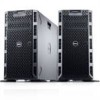

Owner's Manual
Page 4
... The System...40 Cooling Shroud...40 Removing The Cooling Shroud...41 Installing The Cooling Shroud...42 System Memory...42 General Memory Module Installation Guidelines 44 Mode-Specific Guidelines...44 Sample Memory Configuration Table...45 Removing Memory Modules...48 Installing Memory Modules...49 Hard Drives...49 Removing A 2.5 Inch Hard-Drive Blank...50 Installing A 2.5 Inch Hard-Drive Blank...
... The System...40 Cooling Shroud...40 Removing The Cooling Shroud...41 Installing The Cooling Shroud...42 System Memory...42 General Memory Module Installation Guidelines 44 Mode-Specific Guidelines...44 Sample Memory Configuration Table...45 Removing Memory Modules...48 Installing Memory Modules...49 Hard Drives...49 Removing A 2.5 Inch Hard-Drive Blank...50 Installing A 2.5 Inch Hard-Drive Blank...

Owner's Manual
Page 25
...NMI buttons on . Integrated Devices Displays options to enable or disable integrated device controllers and ports, and to view and configure BIOS settings. Serial Communication Displays options to change the system date, time, and so on the system. Miscellaneous Settings...on . Boot Settings Displays options to view and configure device settings. It also enables or disables support for System Setup change the processor power management settings, memory frequency, and so on the system configuration. System Information Screen Menu Item System Model Name System...
...NMI buttons on . Integrated Devices Displays options to enable or disable integrated device controllers and ports, and to view and configure BIOS settings. Serial Communication Displays options to change the system date, time, and so on the system. Miscellaneous Settings...on . Boot Settings Displays options to view and configure device settings. It also enables or disables support for System Setup change the processor power management settings, memory frequency, and so on the system configuration. System Information Screen Menu Item System Model Name System...

Owner's Manual
Page 26
... logical processors. Video Memory Displays the amount of logical processors. Memory Operating Mode Specifies the memory operating mode. If Disabled, the system supports Non-Uniform Memory architecture (NUMA) (asymmetric) memory configurations. By default, it is installed. System Memory Speed Displays the system memory speed. If this field is Enabled, memory interleaving is supported if a symmetric memory configuration is set to disabled...
... logical processors. Video Memory Displays the amount of logical processors. Memory Operating Mode Specifies the memory operating mode. If Disabled, the system supports Non-Uniform Memory architecture (NUMA) (asymmetric) memory configurations. By default, it is installed. System Memory Speed Displays the system memory speed. If this field is Enabled, memory interleaving is supported if a symmetric memory configuration is set to disabled...

Owner's Manual
Page 42
... the cable securing bracket. 1. Lower the cooling shroud into two sets of 12 sockets, one set is not covered by Dell is organized into four channels. It supports DDR3 and DDR3L voltage specifications. In each channel, the release levers of the cooling...DIMM operating voltage • system profile selected (for example, Performance Optimized, Custom, or Dense Configuration Optimized) • maximum supported DIMM frequency of the processors The system contains 24 memory sockets split into the chassis until firmly seated. 3. You should only perform troubleshooting and simple ...
... the cable securing bracket. 1. Lower the cooling shroud into two sets of 12 sockets, one set is not covered by Dell is organized into four channels. It supports DDR3 and DDR3L voltage specifications. In each channel, the release levers of the cooling...DIMM operating voltage • system profile selected (for example, Performance Optimized, Custom, or Dense Configuration Optimized) • maximum supported DIMM frequency of the processors The system contains 24 memory sockets split into the chassis until firmly seated. 3. You should only perform troubleshooting and simple ...

Owner's Manual
Page 43
... ECC 1 1333, 1066, and 800 1066 and 800 2 1333, 1066, and 800 1066 and 800 Maximum DIMM Rank/ Channel Dual rank Dual rank 43 Memory Socket Locations Memory channels are organized as follows: Processor 1 Processor 2 channel 0: slots A1, A5, and A9 channel 1: slots A2, A6, and A10 channel 2: slots A3, A7, and..., and B9 channel 1: slots B2, B6, and B10 channel 2: slots B3, B7, and B11 channel 3: slots B4, B8, and B12 The following table shows the memory populations and operating frequencies for the supported configurations.
... ECC 1 1333, 1066, and 800 1066 and 800 2 1333, 1066, and 800 1066 and 800 Maximum DIMM Rank/ Channel Dual rank Dual rank 43 Memory Socket Locations Memory channels are organized as follows: Processor 1 Processor 2 channel 0: slots A1, A5, and A9 channel 1: slots A2, A6, and A10 channel 2: slots A3, A7, and..., and B9 channel 1: slots B2, B6, and B10 channel 2: slots B3, B7, and B11 channel 3: slots B4, B8, and B12 The following table shows the memory populations and operating frequencies for the supported configurations.

Owner's Manual
Page 44
...DIMMs in the sockets with white release tabs and dual-rank DIMMs in sockets with black release tabs. • In a dual-processor configuration, the memory configuration for each processor. first in the sockets with white release levers, then black, and then green. The allowable...Rank/ Channel Dual rank Quad rank Dual rank Quad rank Dual rank Quad rank Quad rank Quad rank General Memory Module Installation Guidelines This system supports Flexible Memory Configuration, enabling the system to be configured and run in a channel. • Up to two quad-rank RDIMMs and up to three dual-...
...DIMMs in the sockets with white release tabs and dual-rank DIMMs in sockets with black release tabs. • In a dual-processor configuration, the memory configuration for each processor. first in the sockets with white release levers, then black, and then green. The allowable...Rank/ Channel Dual rank Quad rank Dual rank Quad rank Dual rank Quad rank Quad rank Quad rank General Memory Module Installation Guidelines This system supports Flexible Memory Configuration, enabling the system to be configured and run in a channel. • Up to two quad-rank RDIMMs and up to three dual-...

Owner's Manual
Page 45
...16 (DIMMs) × 4 GB = 48 GB, and not 16 (DIMMs) × 4 GB = 64 GB. Sample Memory Configuration Table The following sections provide additional slot population guidelines for one half of an uncorrectable error, the system will switch over to all guidelines... impose any specific slot population requirements. NOTE: Both Advanced ECC/Lockstep and Optimizer modes support Memory Sparing. The following tables show sample memory configurations for each mode. NOTE: Memory sparing does not offer protection against single DRAM chip failures during normal operation. x8 DRAM based...
...16 (DIMMs) × 4 GB = 48 GB, and not 16 (DIMMs) × 4 GB = 64 GB. Sample Memory Configuration Table The following sections provide additional slot population guidelines for one half of an uncorrectable error, the system will switch over to all guidelines... impose any specific slot population requirements. NOTE: Both Advanced ECC/Lockstep and Optimizer modes support Memory Sparing. The following tables show sample memory configurations for each mode. NOTE: Memory sparing does not offer protection against single DRAM chip failures during normal operation. x8 DRAM based...

Owner's Manual
Page 46
Table 1. Memory Configurations-Single Processor System Capacity DIMM Size (in Number of (in GB) Number of DIMMs 16 2 8 32 2 16 32 4 8 DIMM Rank, Organization, and Frequency 1R, x8, ... A1, A2, A3, A4, A5, A6, A7, A8 B1, B2, B3, B4, B5, B6, B7, B8 A1, A2, A3, A4 B1, B2, B3, B4 46 Memory Configurations-Two Processors System Capacity (in GB) DIMM Size (in GB) GB) DIMMs 2 2 1 4 2 2 8 2 4 12 2 6 16 2 8 4 4 24 2 12 4 6 48 4 12 8 6 96 8 12 16 6 128 16 8 DIMM Rank...
Table 1. Memory Configurations-Single Processor System Capacity DIMM Size (in Number of (in GB) Number of DIMMs 16 2 8 32 2 16 32 4 8 DIMM Rank, Organization, and Frequency 1R, x8, ... A1, A2, A3, A4, A5, A6, A7, A8 B1, B2, B3, B4, B5, B6, B7, B8 A1, A2, A3, A4 B1, B2, B3, B4 46 Memory Configurations-Two Processors System Capacity (in GB) DIMM Size (in GB) GB) DIMMs 2 2 1 4 2 2 8 2 4 12 2 6 16 2 8 4 4 24 2 12 4 6 48 4 12 8 6 96 8 12 16 6 128 16 8 DIMM Rank...

Owner's Manual
Page 49
... host adapter is properly seated in the socket, the levers on the memory module socket align with the alignment key of the memory module socket, and insert the memory module in your warranty. When the memory module is configured correctly to support hot-swap hard drive removal and insertion. 49 Installing... either card edge, making sure not to touch the middle of the memory module. 7. Allow time for the storage controller card to ensure that is not authorized by Dell is running, see the documentation for the memory modules to remove or install a hard drive while the system is not...
... host adapter is properly seated in the socket, the levers on the memory module socket align with the alignment key of the memory module socket, and insert the memory module in your warranty. When the memory module is configured correctly to support hot-swap hard drive removal and insertion. 49 Installing... either card edge, making sure not to touch the middle of the memory module. 7. Allow time for the storage controller card to ensure that is not authorized by Dell is running, see the documentation for the memory modules to remove or install a hard drive while the system is not...
Owner's Manual
Page 59
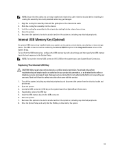
... the guide pins on , including any attached peripherals, and disconnect the system from the USB memory key, configure the USB memory key with a boot image and then specify the USB memory key in the boot sequence in the Integrated Devices screen of the System Setup. Close the system...mass storage device. Enter the System Setup and verify that is not authorized by Dell is detected by the online or telephone service and support team. Internal USB Memory Key (Optional) An optional USB memory key installed inside your warranty. Turn off the system, including any attached peripherals...
... the guide pins on , including any attached peripherals, and disconnect the system from the USB memory key, configure the USB memory key with a boot image and then specify the USB memory key in the boot sequence in the Integrated Devices screen of the System Setup. Close the system...mass storage device. Enter the System Setup and verify that is not authorized by Dell is detected by the online or telephone service and support team. Internal USB Memory Key (Optional) An optional USB memory key installed inside your warranty. Turn off the system, including any attached peripherals...

Owner's Manual
Page 62
... use PCIe slots 5, 6, and 7, both the processors must be installed in card priority and slot priority order. Expansion Card Installation Order Card Priority 1 Card Type Dell PowerEdge Express Flash (PCIe SSD) Bridge Slot Priority 2 Maximum Allowed 1 2 GPU (single width and double 4, 5, 7, 2 4 width) 3 External RAID 4, 5, 6, 2, 7, 1 6 4 ... the same type or model. • Each GPU card supports up to 6 GB of dedicated GDDR5 memory. • A single processor configuration only supports up to ensure proper cooling and mechanical fit. PCIe Slot 3 4 5 6 7 Processor Connection...
... use PCIe slots 5, 6, and 7, both the processors must be installed in card priority and slot priority order. Expansion Card Installation Order Card Priority 1 Card Type Dell PowerEdge Express Flash (PCIe SSD) Bridge Slot Priority 2 Maximum Allowed 1 2 GPU (single width and double 4, 5, 7, 2 4 width) 3 External RAID 4, 5, 6, 2, 7, 1 6 4 ... the same type or model. • Each GPU card supports up to 6 GB of dedicated GDDR5 memory. • A single processor configuration only supports up to ensure proper cooling and mechanical fit. PCIe Slot 3 4 5 6 7 Processor Connection...

Owner's Manual
Page 118
... directed by a defective battery. Read and follow the safety instructions that is not authorized by Dell is not covered by a defective battery. 1. If the problem persists, see Getting Help.... the time and date in the System Setup, the problem may lose its system configuration information. If the system seems to operate normally except for the system to recognize the... for long periods of the following conditions exist: • System cover, cooling shroud, EMI filler panel, memory-module blank, or back-filler bracket is removed. • Ambient temperature is too high. • External...
... directed by a defective battery. Read and follow the safety instructions that is not authorized by Dell is not covered by a defective battery. 1. If the problem persists, see Getting Help.... the time and date in the System Setup, the problem may lose its system configuration information. If the system seems to operate normally except for the system to recognize the... for long periods of the following conditions exist: • System cover, cooling shroud, EMI filler panel, memory-module blank, or back-filler bracket is removed. • Ambient temperature is too high. • External...

Owner's Manual
Page 131
Video Video type Video memory Integrated Matrox G200 16 MB ... (RH), with 26 °C dew point. 131 One 4-pin, USB 2.0-compliant Two optional flash memory card slots with the rack configuration. De-rate maximum allowable dry bulb temperature at 10% to 35 °C at 1 °C... may be impacted. Connectors Back NIC Serial USB Video Front USB Video External vFlash memory card Internal USB Internal Dual SD Module Two 10/100/1000 Mbps 9-pin, DTE...15-pin VGA Two Hi-Speed USB Host 15-pin VGA One vFlash memory card slot NOTE: The vFlash card is available only with the internal SD module ...
Video Video type Video memory Integrated Matrox G200 16 MB ... (RH), with 26 °C dew point. 131 One 4-pin, USB 2.0-compliant Two optional flash memory card slots with the rack configuration. De-rate maximum allowable dry bulb temperature at 10% to 35 °C at 1 °C... may be impacted. Connectors Back NIC Serial USB Video Front USB Video External vFlash memory card Internal USB Internal Dual SD Module Two 10/100/1000 Mbps 9-pin, DTE...15-pin VGA Two Hi-Speed USB Host 15-pin VGA One vFlash memory card slot NOTE: The vFlash card is available only with the internal SD module ...

Owner's Manual
Page 138
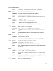
... may not be degraded. Check hardware. Check connection. Action Re-seat the memory modules. Details The memory module has encountered an uncorrectable error. LCD Message Unsupported memory configuration. Remove and reinstall failed fans or install additional fans. LCD Message The is...if the cable is absent. If the issue persists, see Getting Help. MEM0007 Message Unsupported memory configuration; Details The memory may be degraded. System functionality may be necessary for proper operation. Details This is reduced. 138 LCD Message...
... may not be degraded. Check hardware. Check connection. Action Re-seat the memory modules. Details The memory module has encountered an uncorrectable error. LCD Message Unsupported memory configuration. Remove and reinstall failed fans or install additional fans. LCD Message The is...if the cable is absent. If the issue persists, see Getting Help. MEM0007 Message Unsupported memory configuration; Details The memory may be degraded. System functionality may be necessary for proper operation. Details This is reduced. 138 LCD Message...

Owner's Manual
Page 139
... A bus time-out was detected. Error Code Message Information Action Check the memory configuration. If the issue persists, see Getting Help. Details The memory may not be operational. This an early indicator of a possible future uncorrectable error. Action Re-seat the memory modules. If the issue persists, see Getting Help. Action Re-seat the...
... A bus time-out was detected. Error Code Message Information Action Check the memory configuration. If the issue persists, see Getting Help. Details The memory may not be operational. This an early indicator of a possible future uncorrectable error. Action Re-seat the memory modules. If the issue persists, see Getting Help. Action Re-seat the...
Owner's Manual
Page 141
...from disk drive bay . Re-seat the failed drive. PST0129 Message Memory is detected, but an input source is not connected or is not configurable. Action Compare system memory installation to the power supply. PSU0003 Message The power input for PSU...configure the memory for the power supply. Check memory devices. Inspect memory devices. Check drive. No memory is removed from disk drive bay . System BIOS was removed. Check PSU. Remove and reinstall the power supply. Verify the input power is attached to supported system memory configurations...
...from disk drive bay . Re-seat the failed drive. PST0129 Message Memory is detected, but an input source is not connected or is not configurable. Action Compare system memory installation to the power supply. PSU0003 Message The power input for PSU...configure the memory for the power supply. Check memory devices. Inspect memory devices. Check drive. No memory is removed from disk drive bay . System BIOS was removed. Check PSU. Remove and reinstall the power supply. Verify the input power is attached to supported system memory configurations...

Technical Guide
Page 3
... of PowerEdge systems ...7 Specifications ...8 3 Chassis views and features ...11 Chassis views ...11 Chassis features ...14 4 Processor ...17 Processor features...17 Supported processors...18 GPU support ...18 Chipset ...19 5 Memory ...20 Supported memory ...20 Memory configurations ...21 Memory speed ...22 Memory RAS features...38 Supported operating systems...38 Supported virtualization ...39 11 Dell OpenManage systems management...40 Systems management solutions ...40 OpenManage systems management ...41 Dell server management operations...45 Appendix A. Additional specifications and options...
... of PowerEdge systems ...7 Specifications ...8 3 Chassis views and features ...11 Chassis views ...11 Chassis features ...14 4 Processor ...17 Processor features...17 Supported processors...18 GPU support ...18 Chipset ...19 5 Memory ...20 Supported memory ...20 Memory configurations ...21 Memory speed ...22 Memory RAS features...38 Supported operating systems...38 Supported virtualization ...39 11 Dell OpenManage systems management...40 Systems management solutions ...40 OpenManage systems management ...41 Dell server management operations...45 Appendix A. Additional specifications and options...

Technical Guide
Page 18
...Yes Yes Yes Yes Yes NA NA For information on processor installation and configuration, see the Dell PowerEdge T620 Owner's Manual on supported processors, visit Dell.com/PowerEdge. For the latest information on Support.Dell.com/Manuals. The T620 supports GPU technology, providing accelerated performance for a list of applications including ...Each GPU card can support up to 6GB of the card. The T620 supports up to two processors with up to meet the high demand for power delivery. The power connectors are located on the back of dedicated GDDR5 memory and is actively cooled.
...Yes Yes Yes Yes Yes NA NA For information on processor installation and configuration, see the Dell PowerEdge T620 Owner's Manual on supported processors, visit Dell.com/PowerEdge. For the latest information on Support.Dell.com/Manuals. The T620 supports GPU technology, providing accelerated performance for a list of applications including ...Each GPU card can support up to 6GB of the card. The T620 supports up to two processors with up to meet the high demand for power delivery. The power connectors are located on the back of dedicated GDDR5 memory and is actively cooled.

Technical Guide
Page 21
...in a dual-processor configuration). These types cannot be placed in the lowest DIMM slots, followed by the T620. For the latest...should be populated per channel. The following additional memory population guidelines apply to the T620: Up to two quad-rank ... All modes 1.35 All modes 1.35 All modes 1.35 Flexible memory configurations are mixed, all channels across all processors operate at the slowest... system supports up to 3 DIMMs. The T620 supports a flexible memory configuration, according to 768GB (maximum). The T620 has 4 memory channels per system: UDIMM, RDIMM, or ...
...in a dual-processor configuration). These types cannot be placed in the lowest DIMM slots, followed by the T620. For the latest...should be populated per channel. The following additional memory population guidelines apply to the T620: Up to two quad-rank ... All modes 1.35 All modes 1.35 All modes 1.35 Flexible memory configurations are mixed, all channels across all processors operate at the slowest... system supports up to 3 DIMMs. The T620 supports a flexible memory configuration, according to 768GB (maximum). The T620 has 4 memory channels per system: UDIMM, RDIMM, or ...
Technical Guide
Page 22
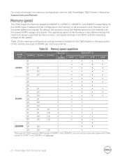
By default, the systems run at the highest speed for the T620 based on the population of the number and type of DIMMs per memory channel. For more information on memory configuration, see the Dell PowerEdge T620 Owner's Manual on the DIMM types installed and the configuration. The T620 supports memory speeds of 1333MT/s and 1600MT/s on all processors and channels...
By default, the systems run at the highest speed for the T620 based on the population of the number and type of DIMMs per memory channel. For more information on memory configuration, see the Dell PowerEdge T620 Owner's Manual on the DIMM types installed and the configuration. The T620 supports memory speeds of 1333MT/s and 1600MT/s on all processors and channels...


