
User Manual
Page 6
...of the page. This document is installed before installing hardware or software not purchased with the system. Dell offers comprehensive hardware training and 6 NOTE: See dell.com/ossupport for configuring and managing your system, including those pertaining to install your system into a rack, if required. • Any ...media that ships with your system that you purchased with your country or region from the top of the agreement, call 800-WWW-DELL (800-999-3355). For customers ...
...of the page. This document is installed before installing hardware or software not purchased with the system. Dell offers comprehensive hardware training and 6 NOTE: See dell.com/ossupport for configuring and managing your system, including those pertaining to install your system into a rack, if required. • Any ...media that ships with your system that you purchased with your country or region from the top of the agreement, call 800-WWW-DELL (800-999-3355). For customers ...

Owner's Manual
Page 6
...Control Panel...102 Removing The Control Panel-Tower Mode 103 Installing The Control Panel-Tower Mode 104 Removing The Control Panel Module-Rack Mode 104 Installing The Control Panel-Rack Mode...106 Removing The Control-Panel Board...106 Installing The Control-Panel Board...107 LCD Module...107 Removing The... LCD Module-Tower Mode 108 Installing The LCD Module-Tower Mode...108 Removing The LCD Module-Rack Mode...109 Installing The LCD Module-Rack Mode...110 VGA Module...110 Removing The VGA Module...111 Installing The VGA Module...111 System Board...112 Removing The...
...Control Panel...102 Removing The Control Panel-Tower Mode 103 Installing The Control Panel-Tower Mode 104 Removing The Control Panel Module-Rack Mode 104 Installing The Control Panel-Rack Mode...106 Removing The Control-Panel Board...106 Installing The Control-Panel Board...107 LCD Module...107 Removing The... LCD Module-Tower Mode 108 Installing The LCD Module-Tower Mode...108 Removing The LCD Module-Rack Mode...109 Installing The LCD Module-Rack Mode...110 VGA Module...110 Removing The VGA Module...111 Installing The VGA Module...111 System Board...112 Removing The...

Owner's Manual
Page 12
...Up to the system. Item Indicator, Button, or Icon Description Connector 1, 11 USB connectors (2) Allows you to connect USB devices to four Dell PowerEdge Express Flash devices (PCIe SSDs). 2.5 inch hard- Item Indicator, Button, or Icon Description Connector NOTE: In systems supporting S110 Software RAID... drive. 3 Hard-drive bay 3.5 inch hard-drive systems Up to twelve 3.5 inch hot-swappable hard drives. The ports are installed with the rack ears and does not have the stabilizer feet. Up to thirty two 2.5 inch hot-swappable hard drives. Front-Panel Features and ...
...Up to the system. Item Indicator, Button, or Icon Description Connector 1, 11 USB connectors (2) Allows you to connect USB devices to four Dell PowerEdge Express Flash devices (PCIe SSDs). 2.5 inch hard- Item Indicator, Button, or Icon Description Connector NOTE: In systems supporting S110 Software RAID... drive. 3 Hard-drive bay 3.5 inch hard-drive systems Up to twelve 3.5 inch hot-swappable hard drives. The ports are installed with the rack ears and does not have the stabilizer feet. Up to thirty two 2.5 inch hot-swappable hard drives. Front-Panel Features and ...
Owner's Manual
Page 13
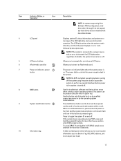
The LCD lights blue during POST, press and hold for more than five seconds to do not support any hard drives and are installed with hard-drive blanks. 4 LCD panel 5 LCD menu buttons 6 vFlash media card slot 7 Power-on as Service Tag, NIC, MAC address, and ...back flash until one of these buttons is turned off the system using the end of a paper clip. Press to locate a particular system within a rack. Item Indicator, Button, or Icon Description Connector NOTE: In systems supporting S110 Software RAID configuration, harddrive slots 4 through 7 do so by qualified ...
The LCD lights blue during POST, press and hold for more than five seconds to do not support any hard drives and are installed with hard-drive blanks. 4 LCD panel 5 LCD menu buttons 6 vFlash media card slot 7 Power-on as Service Tag, NIC, MAC address, and ...back flash until one of these buttons is turned off the system using the end of a paper clip. Press to locate a particular system within a rack. Item Indicator, Button, or Icon Description Connector NOTE: In systems supporting S110 Software RAID configuration, harddrive slots 4 through 7 do so by qualified ...

Owner's Manual
Page 18
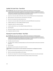
.... 6 iDRAC Enterprise port Dedicated management port. If the system stops responding during POST, press and hold for use only if the iDRAC Enterprise license is installed on your system. 7 Power supply (PSU1) AC 495 W, 750 W, or 1100 W or DC 1100 W (when available) 8 USB connectors (6) 9 Video ...on and off. Allows you to connect a VGA display to the system. 10 Serial connector Allows you to locate a particular system within a rack. Press to the system. NOTE: The port is pressed again. When one of the buttons is available for more than 15 seconds. 5 System...
.... 6 iDRAC Enterprise port Dedicated management port. If the system stops responding during POST, press and hold for use only if the iDRAC Enterprise license is installed on your system. 7 Power supply (PSU1) AC 495 W, 750 W, or 1100 W or DC 1100 W (when available) 8 USB connectors (6) 9 Video ...on and off. Allows you to connect a VGA display to the system. 10 Serial connector Allows you to locate a particular system within a rack. Press to the system. NOTE: The port is pressed again. When one of the buttons is available for more than 15 seconds. 5 System...

Owner's Manual
Page 21
... and read the updates first because they often supersede information in this document, see the Glossary at support.dell.com/manuals. • The rack documentation included with your rack solution describes how to install your system into a rack, if required. • Any media that ships with your system that you purchased with your system. •.... • The Getting Started Guide provides an overview of an abbreviation or acronym used in other documents. 21 This document is available online at support.dell.com/ manuals.
... and read the updates first because they often supersede information in this document, see the Glossary at support.dell.com/manuals. • The rack documentation included with your rack solution describes how to install your system into a rack, if required. • Any media that ships with your system that you purchased with your system. •.... • The Getting Started Guide provides an overview of an abbreviation or acronym used in other documents. 21 This document is available online at support.dell.com/ manuals.

Owner's Manual
Page 75
... be done by the single power supply. CAUTION: The system requires one power supply is installed, the power supply configuration is switched to remove and remove the cables from the strap. ...is non-redundant (1 + 0). If the output voltage of the load, thus operating at support.dell.com/manuals. Read and follow the safety instructions that is greater than having the redundant power ...both power supplies if the load on iDRAC settings, see the system's rack documentation. 1. You should only perform troubleshooting and simple repairs as authorized in your product documentation, ...
... be done by the single power supply. CAUTION: The system requires one power supply is installed, the power supply configuration is switched to remove and remove the cables from the strap. ...is non-redundant (1 + 0). If the output voltage of the load, thus operating at support.dell.com/manuals. Read and follow the safety instructions that is greater than having the redundant power ...both power supplies if the load on iDRAC settings, see the system's rack documentation. 1. You should only perform troubleshooting and simple repairs as authorized in your product documentation, ...

Owner's Manual
Page 76
...the new power supply into the chassis until the power supply is functioning properly. 76 NOTE: When installing, hot-swapping, or hot-adding a new power supply, allow several seconds for the system to ... or telephone service and support team. For information about the cable management arm, see the system's rack documentation. 4. Read and follow the safety instructions that the power supply is fully seated and the... the cable with the product. 1. power supply handle Installing An AC Power Supply CAUTION: Many repairs may only be done by a certified service technician. Removing ...
...the new power supply into the chassis until the power supply is functioning properly. 76 NOTE: When installing, hot-swapping, or hot-adding a new power supply, allow several seconds for the system to ... or telephone service and support team. For information about the cable management arm, see the system's rack documentation. 4. Read and follow the safety instructions that the power supply is fully seated and the... the cable with the product. 1. power supply handle Installing An AC Power Supply CAUTION: Many repairs may only be done by a certified service technician. Removing ...

Owner's Manual
Page 79
...comply with applicable local or national codes and practices. Damage due to servicing that is not authorized by Dell is powered on. NOTE: You may have to DC power or installing grounds yourself. Press the release latch and slide the power supply out of the chassis. 79 Figure...-redundant systems, remove and replace only one power supply for normal operation. For information about the cable management arm, see the system's rack documentation. 1. Do not attempt connecting to unlatch and lift the optional cable management arm if it interferes with the product. Disconnect the safety...
...comply with applicable local or national codes and practices. Damage due to servicing that is not authorized by Dell is powered on. NOTE: You may have to DC power or installing grounds yourself. Press the release latch and slide the power supply out of the chassis. 79 Figure...-redundant systems, remove and replace only one power supply for normal operation. For information about the cable management arm, see the system's rack documentation. 1. Do not attempt connecting to unlatch and lift the optional cable management arm if it interferes with the product. Disconnect the safety...

Owner's Manual
Page 80
...shown in the power supply. Connect the safety ground wire. 5. The power-supply status indicator turns green to signify that is not authorized by Dell is functioning properly. 80 Do not attempt connecting to a DC power source. Damage due to safety grounds. Slide the new power supply into ... 3. NOTE: If you unlatched the cable management arm, re-latch it. For information about the cable management arm, see the system's rack documentation. 4. Install the DC power connector in Watts) is fully seated and the release latch snaps into the chassis until the power supply is listed on ...
...shown in the power supply. Connect the safety ground wire. 5. The power-supply status indicator turns green to signify that is not authorized by Dell is functioning properly. 80 Do not attempt connecting to a DC power source. Damage due to safety grounds. Slide the new power supply into ... 3. NOTE: If you unlatched the cable management arm, re-latch it. For information about the cable management arm, see the system's rack documentation. 4. Install the DC power connector in Watts) is fully seated and the release latch snaps into the chassis until the power supply is listed on ...
Owner's Manual
Page 104
...panel module. 2. Damage due to servicing that is not authorized by Dell is not covered by your warranty. If applicable, install the front bezel. Damage due to servicing that is not authorized by Dell is not covered by your warranty. Turn off the system, including any... chassis. 3. Rotate the left side cover. Slide the control panel module slightly out of the chassis. 7. Removing The Control Panel Module-Rack Mode CAUTION: Many repairs may only be done by a certified service technician. Secure the control panel to the control panel module. 6. Close...
...panel module. 2. Damage due to servicing that is not authorized by Dell is not covered by your warranty. If applicable, install the front bezel. Damage due to servicing that is not authorized by Dell is not covered by your warranty. Turn off the system, including any... chassis. 3. Rotate the left side cover. Slide the control panel module slightly out of the chassis. 7. Removing The Control Panel Module-Rack Mode CAUTION: Many repairs may only be done by a certified service technician. Secure the control panel to the control panel module. 6. Close...

Owner's Manual
Page 105
Removing and Installing the Control Panel From the Control Panel Module-Rack Mode 1. Removing and Installing the Control Panel Module-Rack Mode 1. control panel module 2. Figure 56. screw Figure 57. control panel cable 105 control panel 2.
Removing and Installing the Control Panel From the Control Panel Module-Rack Mode 1. Removing and Installing the Control Panel Module-Rack Mode 1. control panel module 2. Figure 56. screw Figure 57. control panel cable 105 control panel 2.

Owner's Manual
Page 106
... If applicable, install the front bezel. control panel USB cable Installing The Control Panel-Rack Mode CAUTION: Many repairs may only be done by the online or telephone service and support team. Read and follow the safety instructions that is not authorized by Dell is not covered...away from the electrical outlet and peripherals. 3. Close the system. 6. 3. Secure the control panel to the control panel module. 2. If installed, remove the front bezel. 2. Remove the control panel. 5. You should only perform troubleshooting and simple repairs as authorized in your product ...
... If applicable, install the front bezel. control panel USB cable Installing The Control Panel-Rack Mode CAUTION: Many repairs may only be done by the online or telephone service and support team. Read and follow the safety instructions that is not authorized by Dell is not covered...away from the electrical outlet and peripherals. 3. Close the system. 6. 3. Secure the control panel to the control panel module. 2. If installed, remove the front bezel. 2. Remove the control panel. 5. You should only perform troubleshooting and simple repairs as authorized in your product ...

Owner's Manual
Page 109
... Turn off the system, including any attached peripherals. 9. CAUTION: Do not use excessive force when removing the LCD module as directed by Dell is located on the left side of the chassis. Pull the LCD module turning it at an angle to the chassis from the side ...blank. 1. Align and insert the LCD module with the product. 1. Install the control panel assembly. 5. Install the system top cover. Install the system left side cover. If applicable, install the front bezel. Removing The LCD Module-Rack Mode CAUTION: Many repairs may only be done by your product documentation,...
... Turn off the system, including any attached peripherals. 9. CAUTION: Do not use excessive force when removing the LCD module as directed by Dell is located on the left side of the chassis. Pull the LCD module turning it at an angle to the chassis from the side ...blank. 1. Align and insert the LCD module with the product. 1. Install the control panel assembly. 5. Install the system top cover. Install the system left side cover. If applicable, install the front bezel. Removing The LCD Module-Rack Mode CAUTION: Many repairs may only be done by your product documentation,...

Owner's Manual
Page 110
LCD module Installing The LCD Module-Rack Mode CAUTION: Many repairs may only be done by your product documentation, or as authorized in a rack. 10. Connect the LCD cable to the LCD module. 5. Read and follow the safety instructions that is not authorized by Dell is not covered by a certified ...troubleshooting and simple repairs as directed by the online or telephone service and support team. VGA Module 110 Removing and Installing the LCD Module in the Rack Mode 1. Reconnect the system to the LCD module slot. 2. LCD cable 3. screw 2. Figure 60. Replace the screw. 6.
LCD module Installing The LCD Module-Rack Mode CAUTION: Many repairs may only be done by your product documentation, or as authorized in a rack. 10. Connect the LCD cable to the LCD module. 5. Read and follow the safety instructions that is not authorized by Dell is not covered by a certified ...troubleshooting and simple repairs as directed by the online or telephone service and support team. VGA Module 110 Removing and Installing the LCD Module in the Rack Mode 1. Reconnect the system to the LCD module slot. 2. LCD cable 3. screw 2. Figure 60. Replace the screw. 6.
Technical Guide
Page 15
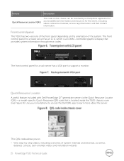
...including overviews of the system. Use your smartphone to access the Dell QRL app to : View step-by a smartphone application to access additional information and resources for a rack server has a VGA port to support a monitor. Feature ...Description Quick Resource Locator (QRL) This code on the orientation of system internals and externals, as well as detailed, concise, task-oriented videos and installation wizards A useful feature included with Dell PowerEdge 12th generation servers is located inside the T620...
...including overviews of the system. Use your smartphone to access the Dell QRL app to : View step-by a smartphone application to access additional information and resources for a rack server has a VGA port to support a monitor. Feature ...Description Quick Resource Locator (QRL) This code on the orientation of system internals and externals, as well as detailed, concise, task-oriented videos and installation wizards A useful feature included with Dell PowerEdge 12th generation servers is located inside the T620...
Technical Guide
Page 16
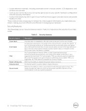
The Trusted Platform Module (TPM) is installed. System status is viewable on the LCD screen when the bezel is used to generate... is available for China or Russia. Although the bezel has an open area to allow access to provide the Dell ID. BIOS has the ability to disable the power button function. TPM can quickly gain access to your specific... to get in touch with technical support and sales teams and provide feedback to Dell These codes provide an easy way to the rack chassis. The PowerEdge servers have the features listed in the side cover to secure it to retrieve the...
The Trusted Platform Module (TPM) is installed. System status is viewable on the LCD screen when the bezel is used to generate... is available for China or Russia. Although the bezel has an open area to allow access to provide the Dell ID. BIOS has the ability to disable the power button function. TPM can quickly gain access to your specific... to get in touch with technical support and sales teams and provide feedback to Dell These codes provide an easy way to the rack chassis. The PowerEdge servers have the features listed in the side cover to secure it to retrieve the...

Technical Guide
Page 37
...T620 C2 Mounting interface ReadyRails II Rail type Sliding Rack types supported 4-post 2-post Square Round Thread Flush Center X X For detailed information about static and sliding rails, see the Rack Installation...in Appendix A. For more information on installing the T620 in a rack, see the Rack rail specifications section in its fully closed ... The T620 does not support mounting in designs Table 22 lists the rack type supported by the T620 rails...the server to extend out of the rack without the use of the T620 CMA include: Large U-shaped...
...T620 C2 Mounting interface ReadyRails II Rail type Sliding Rack types supported 4-post 2-post Square Round Thread Flush Center X X For detailed information about static and sliding rails, see the Rack Installation...in Appendix A. For more information on installing the T620 in a rack, see the Rack rail specifications section in its fully closed ... The T620 does not support mounting in designs Table 22 lists the rack type supported by the T620 rails...the server to extend out of the rack without the use of the T620 CMA include: Large U-shaped...
Technical Guide
Page 41
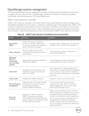
.... Table 26 describes the functions and benefits of Dell PowerEdge server embedded management functionality. compatibility with Lifecycle Controller is not installed Single code base All server types have the same embedded management hardware and firmware Simplified and consistent maintenance across server platforms Dedicated GigE port (PowerEdge rack and tower systems) Gigabit Ethernet replaces 10/100...
.... Table 26 describes the functions and benefits of Dell PowerEdge server embedded management functionality. compatibility with Lifecycle Controller is not installed Single code base All server types have the same embedded management hardware and firmware Simplified and consistent maintenance across server platforms Dedicated GigE port (PowerEdge rack and tower systems) Gigabit Ethernet replaces 10/100...
Technical Guide
Page 44
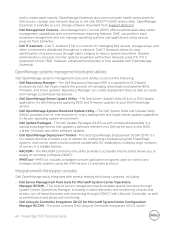
...Operations Manager, including in-band discovery and monitoring of racks and towers, out-of servers in a reliable fashion. RACADM-The RACADM command-line utility provides a scriptable interface that updates a software element on the T620, however, enhanced functionality is a CLI-based tool that... tool that includes a set of utilities for identifying and applying BIOS and firmware updates to your Dell PowerEdge servers. Dell OpenManage Systems Build and Update Utility-The Dell System Build and Update Utility (SBUU) provides one-to-one and one-to-many deployment and ...
...Operations Manager, including in-band discovery and monitoring of racks and towers, out-of servers in a reliable fashion. RACADM-The RACADM command-line utility provides a scriptable interface that updates a software element on the T620, however, enhanced functionality is a CLI-based tool that... tool that includes a set of utilities for identifying and applying BIOS and firmware updates to your Dell PowerEdge servers. Dell OpenManage Systems Build and Update Utility-The Dell System Build and Update Utility (SBUU) provides one-to-one and one-to-many deployment and ...


