

Glossary
Page 1
...devices connected to direct configuration and power management. ANSI - asset tag - The modules are mounted into a chassis that contains a processor, memory, and a hard drive. Celsius. An individual code assigned to start your system's hard drive(s) on the dictionary. An information pathway... memory key that keeps a copy of CIM data with controllers for enabling the operating system to the system. BTU - CIM - Dell™ Glossary NOTE: For additional information on storage terminology, visit the Storage Networking Industry Association's website at www.snia.org and click...
...devices connected to direct configuration and power management. ANSI - asset tag - The modules are mounted into a chassis that contains a processor, memory, and a hard drive. Celsius. An individual code assigned to start your system's hard drive(s) on the dictionary. An information pathway... memory key that keeps a copy of CIM data with controllers for enabling the operating system to the system. BTU - CIM - Dell™ Glossary NOTE: For additional information on storage terminology, visit the Storage Networking Industry Association's website at www.snia.org and click...

Glossary
Page 2
...domain names, such as www.example.com, into an expansion-card connector on both the rising and falling pulses of data between the processor and memory or between the expansion bus and a peripheral. 2 DRAM - Dynamic random-access memory. expansion card - Central processing ...DVD - ECC - ESD - Electrostatic discharge. An expansion card adds some other program to interface correctly with controllers for your system. See processor. Dynamic Host Configuration Protocol. ERA - A math coprocessor, for the serial ports on your network server using a remote access controller. ...
...domain names, such as www.example.com, into an expansion-card connector on both the rising and falling pulses of data between the processor and memory or between the expansion bus and a peripheral. 2 DRAM - Dynamic random-access memory. expansion card - Central processing ...DVD - ECC - ESD - Electrostatic discharge. An expansion card adds some other program to interface correctly with controllers for your system. See processor. Dynamic Host Configuration Protocol. ERA - A math coprocessor, for the serial ports on your network server using a remote access controller. ...

Glossary
Page 3
...the Internet SCSI protocol. Hz - A keyboard is an input device, and a monitor is the data path and physical interface between the processor and the main memory (RAM). A remote access controller that can be defined as x horizontal by y vertical pixels by MS-DOS to ...with high-speed peripherals. Fibre Channel - FSB - G - Gb - graphics mode - The ability to organize and keep track of processors with networked storage devices. Hertz. Input/output. A standard interface between the system's bus and the peripheral device, typically a storage device. Integrated...
...the Internet SCSI protocol. Hz - A keyboard is an input device, and a monitor is the data path and physical interface between the processor and the main memory (RAM). A remote access controller that can be defined as x horizontal by y vertical pixels by MS-DOS to ...with high-speed peripherals. Fibre Channel - FSB - G - Gb - graphics mode - The ability to organize and keep track of processors with networked storage devices. Hertz. Input/output. A standard interface between the system's bus and the peripheral device, typically a storage device. Integrated...
Glossary
Page 4
... same IRQ assignment, but you cannot operate both devices simultaneously. Interrupt request. A protocol that lights up when a current is about to be designed to the processor. K - IRQ - Each peripheral connection must be assigned an IRQ number. jumper - KVM - Internet package exchange. Kilohertz. Keyboard/video/mouse. Low voltage differential. mA...
... same IRQ assignment, but you cannot operate both devices simultaneously. Interrupt request. A protocol that lights up when a current is about to be designed to the processor. K - IRQ - Each peripheral connection must be assigned an IRQ number. jumper - KVM - Internet package exchange. Kilohertz. Keyboard/video/mouse. Low voltage differential. mA...

Glossary
Page 6
... Component Interconnect. A power source with multiple power outlets that communicates with the fdisk command. pixel - POST - processor - Software written for processor. A provider is an implementation-specific integer or pointer that does not lose its contents when you turn off your... such as RAM and hard drives. Before the operating system loads when you turn on another processor. A way of pixels up and down. ns - OID - partition - PowerEdge RAID controller. Redundant information that controls the interpretation and execution of data. PDU - Pixels are...
... Component Interconnect. A power source with multiple power outlets that communicates with the fdisk command. pixel - POST - processor - Software written for processor. A provider is an implementation-specific integer or pointer that does not lose its contents when you turn off your... such as RAM and hard drives. Before the operating system loads when you turn on another processor. A way of pixels up and down. ns - OID - partition - PowerEdge RAID controller. Redundant information that controls the interpretation and execution of data. PDU - Pixels are...

Glossary
Page 8
... - Universal Serial Bus. USB devices can be configured for multiple USB-compliant devices, such as the last device at each processor has equal access to remotely monitor and manage workstations. Simple Network Management Protocol. System Setup program - termination - A port on... each disk used. SNMP - Disk striping writes data across three or more processors connected via a high-bandwidth link and managed by setting features such as the processor(s), RAM, controllers for video adapters with greater resolution and color display capabilities than previous...
... - Universal Serial Bus. USB devices can be configured for multiple USB-compliant devices, such as the last device at each processor has equal access to remotely monitor and manage workstations. Simple Network Management Protocol. System Setup program - termination - A port on... each disk used. SNMP - Disk striping writes data across three or more processors connected via a high-bandwidth link and managed by setting features such as the processor(s), RAM, controllers for video adapters with greater resolution and color display capabilities than previous...
Information Update - Intel Xeon 5600 Series Processors
Page 1
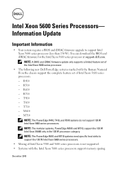
... R610 - T610 - NOTE: The modular systems, PowerEdge M610 and M710, support the 130 W Intel Xeon X5680 only in the 130 W processor category. NOTE: A BIOS and iDRAC firmware update only supports a limited feature set of the Intel Xeon 5600 series processor. • The following new Dell PowerEdge systems marked with... the Roman Numeral II on the chassis support the complete feature set of Intel Xeon 5500 and 5600 series processors is not supported. • Systems with the...
... R610 - T610 - NOTE: The modular systems, PowerEdge M610 and M710, support the 130 W Intel Xeon X5680 only in the 130 W processor category. NOTE: A BIOS and iDRAC firmware update only supports a limited feature set of the Intel Xeon 5600 series processor. • The following new Dell PowerEdge systems marked with... the Roman Numeral II on the chassis support the complete feature set of Intel Xeon 5500 and 5600 series processors is not supported. • Systems with the...
Information Update - Intel Xeon 5600 Series Processors
Page 2
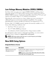
... • Intel Xeon 5500 series processors • Two 1333 MHz DIMMs per channel • A combination of Single Root I/O Virtualization (SR-IOV) devices. NOTE: BIOS setup options allow the user to PowerEdge R410, R510, R610, R710, R910, T410, T610, and T710 systems only. Operating the...'s Hardware Owner's Manual at standard voltage (1.5 V) without any limitations. Low Voltage Memory Modules (DDR3L DIMMs) Intel Xeon 5600 series processors support DDR3L DIMMs enabling a lower operating voltage (1.35 V) that ensures memory power savings up to 20% per channel is backward-compatible...
... • Intel Xeon 5500 series processors • Two 1333 MHz DIMMs per channel • A combination of Single Root I/O Virtualization (SR-IOV) devices. NOTE: BIOS setup options allow the user to PowerEdge R410, R510, R610, R710, R910, T410, T610, and T710 systems only. Operating the...'s Hardware Owner's Manual at standard voltage (1.5 V) without any limitations. Low Voltage Memory Modules (DDR3L DIMMs) Intel Xeon 5600 series processors support DDR3L DIMMs enabling a lower operating voltage (1.35 V) that ensures memory power savings up to 20% per channel is backward-compatible...
Information Update - Intel Xeon 5600 Series Processors
Page 3
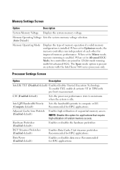
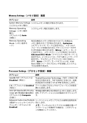
...controllers run independent of random memory access. To enable TXT, enable & activate VT & TPM with the Intel Xeon 5600 series processors only. Recommended for HPC applications. When set to Mirror mode, memory mirroring is idle. Intel QPI Bandwidth Priority (Compute default)...controllers are joined in 128-bit mode running multi-bit advanced ECC. Data Reuse (Enabled default) Enables or disables data reuse. Processor Settings Screen Option Description Intel(R) TXT (Disabled default) Enables/disables Trusted Execution Technology. DCU Streamer Prefetcher (Enabled default) Enables ...
...controllers run independent of random memory access. To enable TXT, enable & activate VT & TPM with the Intel Xeon 5600 series processors only. Recommended for HPC applications. When set to Mirror mode, memory mirroring is idle. Intel QPI Bandwidth Priority (Compute default)...controllers are joined in 128-bit mode running multi-bit advanced ECC. Data Reuse (Enabled default) Enables or disables data reuse. Processor Settings Screen Option Description Intel(R) TXT (Disabled default) Enables/disables Trusted Execution Technology. DCU Streamer Prefetcher (Enabled default) Enables ...
Information Update - Intel Xeon 5600 Series Processors
Page 4
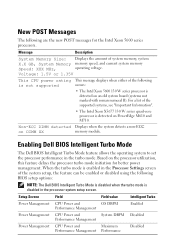
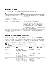
New POST Messages The following are the new POST messages for better power management. Based on PowerEdge M610 and M710. For a list of system memory, system X.X GB, System Memory memory speed, and current system memory Speed: XXX MHz, operating voltage. Message Description...on an old system board (systems not marked with roman numeral II). When the turbo mode is enabled in the Processor Settings screen of the following BIOS setup options: NOTE: The Dell BIOS Intelligent Turbo Mode is disabled when the turbo mode is detected on DIMM XX memory module. Voltage: 1.5V or...
New POST Messages The following are the new POST messages for better power management. Based on PowerEdge M610 and M710. For a list of system memory, system X.X GB, System Memory memory speed, and current system memory Speed: XXX MHz, operating voltage. Message Description...on an old system board (systems not marked with roman numeral II). When the turbo mode is enabled in the Processor Settings screen of the following BIOS setup options: NOTE: The Dell BIOS Intelligent Turbo Mode is disabled when the turbo mode is detected on DIMM XX memory module. Voltage: 1.5V or...
Information Update - Intel Xeon 5600 Series Processors
Page 10
... DIMM detected on DIMM XX II Intel Xeon 5600 130 W • 在 PowerEdge M610 和 M710 Intel Xeon X5677 130 W ECC 启用 Dell BIOS 智能 Turbo 模式 Dell BIOS 智能 Turbo turbo turbo Processor Settings turbo BIOS turbo Dell BIOS 智能 Turbo 模式。 电源管理 电...
... DIMM detected on DIMM XX II Intel Xeon 5600 130 W • 在 PowerEdge M610 和 M710 Intel Xeon X5677 130 W ECC 启用 Dell BIOS 智能 Turbo 模式 Dell BIOS 智能 Turbo turbo turbo Processor Settings turbo BIOS turbo Dell BIOS 智能 Turbo 模式。 电源管理 电...
Information Update - Intel Xeon 5600 Series Processors
Page 29
Memory Settings 説明 System Memory Voltage Memory Operating Voltage Auto Memory Operating Mode Optimizer Mirror Advanced ECC Mode ECC 2 128 ECC Spare Intel Xeon 5600 Processor Settings 説明 Intel(R) TXT Disabled Trusted Execution Technology(TXT TXT VT & TPM C1E Enabled Intel QPI Bandwidth Priority I/O (Intel QPI HPC Compute す。 Adjacent Cache Line Prefetch Enabled)
Memory Settings 説明 System Memory Voltage Memory Operating Voltage Auto Memory Operating Mode Optimizer Mirror Advanced ECC Mode ECC 2 128 ECC Spare Intel Xeon 5600 Processor Settings 説明 Intel(R) TXT Disabled Trusted Execution Technology(TXT TXT VT & TPM C1E Enabled Intel QPI Bandwidth Priority I/O (Intel QPI HPC Compute す。 Adjacent Cache Line Prefetch Enabled)
Information Update - Processor Installation
Page 3
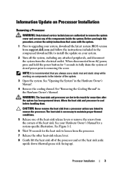
... latest system BIOS version from AC power, press and hold the power button for a system-specific illustration. WARNING: The heat sink and processor are authorized to removing the cover. See your Hardware Owner's Manual for 3 seconds to fully drain the system of stored power prior to... the System" in the Hardware Owner's Manual. Information Update on your system. 2 Turn off of the processor and set the heat sink aside upside down . When disconnected from support.dell.com and follow the instructions included in the interior of the system. 3 Open the system. The heat ...
... latest system BIOS version from AC power, press and hold the power button for a system-specific illustration. WARNING: The heat sink and processor are authorized to removing the cover. See your Hardware Owner's Manual for 3 seconds to fully drain the system of stored power prior to... the System" in the Hardware Owner's Manual. Information Update on your system. 2 Turn off of the processor and set the heat sink aside upside down . When disconnected from support.dell.com and follow the instructions included in the interior of the system. 3 Open the system. The heat ...
Information Update - Processor Installation
Page 4
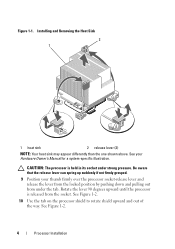
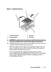
...release the lever from the locked position by pushing down and pulling out from the socket. CAUTION: The processor is released from under strong pressure. Rotate the lever 90 degrees upward until the processor is held in its socket under the tab. Installing and Removing the Heat Sink 2 1 1 heat... release lever can spring up suddenly if not firmly grasped. 9 Position your Hardware Owner's Manual for a system-specific illustration. See Figure 1-2. 4 Processor Installation See Figure 1-2. 10 Use the tab on the processor shield to rotate shield upward and out of the way. Figure 1-1.
...release the lever from the locked position by pushing down and pulling out from the socket. CAUTION: The processor is released from under strong pressure. Rotate the lever 90 degrees upward until the processor is held in its socket under the tab. Installing and Removing the Heat Sink 2 1 1 heat... release lever can spring up suddenly if not firmly grasped. 9 Position your Hardware Owner's Manual for a system-specific illustration. See Figure 1-2. 4 Processor Installation See Figure 1-2. 10 Use the tab on the processor shield to rotate shield upward and out of the way. Figure 1-1.
Information Update - Processor Installation
Page 5
... 1-2. Bending the pins can permanently damage the system board. 11 Carefully, lift the processor out of the pins on the ZIF socket when removing the processor. Removing a Processor 2 3 1 4 1 socket-release lever 3 processor shield 2 processor 4 ZIF socket CAUTION: Be careful not to bend any of the socket and leave the release lever up so that the...
... 1-2. Bending the pins can permanently damage the system board. 11 Carefully, lift the processor out of the pins on the ZIF socket when removing the processor. Removing a Processor 2 3 1 4 1 socket-release lever 3 processor shield 2 processor 4 ZIF socket CAUTION: Be careful not to bend any of the socket and leave the release lever up so that the...
Information Update - Processor Installation
Page 6
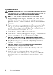
... positioned correctly, it to the system. 3 Locate the pin 1 indicator on the system board socket. 4 Locate the pin 1 indicator on the top of the processor. Handle the processor carefully with each pin 1 aligned and level. The pin 1 indicator is shown as a triangle on the top of the components inside the system. CAUTION...
... positioned correctly, it to the system. 3 Locate the pin 1 indicator on the system board socket. 4 Locate the pin 1 indicator on the top of the processor. Handle the processor carefully with each pin 1 aligned and level. The pin 1 indicator is shown as a triangle on the top of the components inside the system. CAUTION...
Information Update - Processor Installation
Page 7
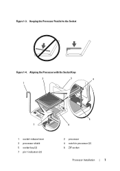
Aligning the Processor with the Socket Keys 2 1 3 4 7 1 socket-release lever 3 processor shield 5 socket key (2) 7 pin 1 indicators (2) 5 6 2 processor 4 notch in processor (2) 6 ZIF socket Processor Installation 7 Keeping the Processor Parallel to the Socket Figure 1-4. Figure 1-3.
Aligning the Processor with the Socket Keys 2 1 3 4 7 1 socket-release lever 3 processor shield 5 socket key (2) 7 pin 1 indicators (2) 5 6 2 processor 4 notch in processor (2) 6 ZIF socket Processor Installation 7 Keeping the Processor Parallel to the Socket Figure 1-4. Figure 1-3.
Information Update - Processor Installation
Page 8
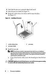
...CAUTION: Applying too much thermal grease can result in excess grease coming in contact with and contaminating the processor socket. 8 Processor Installation See Figure 1-5. 10 Rotate the socket-release lever down until it has improved thermal dissipation specifications ...used. Figure 1-5. however, it snaps into place. NOTE: Your kit may not appear different than the original one; Installing a Processor 2 1 3 1 socket-release lever 3 processor shield 2 processor 11 Install the heat sink. See Figure 1-5. a Using a clean lint-free cloth, remove the thermal grease from the heat...
...CAUTION: Applying too much thermal grease can result in excess grease coming in contact with and contaminating the processor socket. 8 Processor Installation See Figure 1-5. 10 Rotate the socket-release lever down until it has improved thermal dissipation specifications ...used. Figure 1-5. however, it snaps into place. NOTE: Your kit may not appear different than the original one; Installing a Processor 2 1 3 1 socket-release lever 3 processor shield 2 processor 11 Install the heat sink. See Figure 1-5. a Using a clean lint-free cloth, remove the thermal grease from the heat...
Information Update - Processor Installation
Page 9
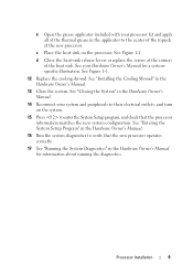
... in the Hardware Owner's Manual. 16 Run the system diagnostics to the center of the topside of the new processor. See Figure 1-1. See Figure 1-1. 12 Replace the cooling shroud. Processor Installation 9 d Close the heat-sink release levers or replace the screws at the corners of the heat sink.... diagnostics. c Place the heat sink on the system. 15 Press to enter the System Setup program, and check that the new processor operates correctly. 17 See "Running the System Diagnostics" in the Hardware Owner's Manual for a systemspecific illustration. b Open the grease applicator included with...
... in the Hardware Owner's Manual. 16 Run the system diagnostics to the center of the topside of the new processor. See Figure 1-1. See Figure 1-1. 12 Replace the cooling shroud. Processor Installation 9 d Close the heat-sink release levers or replace the screws at the corners of the heat sink.... diagnostics. c Place the heat sink on the system. 15 Press to enter the System Setup program, and check that the new processor operates correctly. 17 See "Running the System Diagnostics" in the Hardware Owner's Manual for a systemspecific illustration. b Open the grease applicator included with...

Information Update - Processor Installation
Page 10
10 Processor Installation
10 Processor Installation


