
Information Update - Intel Xeon 5600 Series Processors
Page 1
...upgrade to support the 130 W Intel Xeon 5600 series processors. • Mixing of Intel Xeon 5500 and 5600 series processors is not supported. • Systems with the Roman Numeral II on the chassis support the complete feature set of the Intel Xeon 5600 series processor. • The following new Dell PowerEdge... systems marked with the Intel Xeon 5600 series processors support memory sparing. NOTE: The modular systems, PowerEdge M610 and M710, support the 130 W Intel Xeon X5680 only in the 130...
...upgrade to support the 130 W Intel Xeon 5600 series processors. • Mixing of Intel Xeon 5500 and 5600 series processors is not supported. • Systems with the Roman Numeral II on the chassis support the complete feature set of the Intel Xeon 5600 series processor. • The following new Dell PowerEdge... systems marked with the Intel Xeon 5600 series processors support memory sparing. NOTE: The modular systems, PowerEdge M610 and M710, support the 130 W Intel Xeon X5680 only in the 130...
Hardware Owner's Manual
Page 40
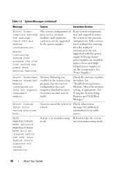
...supply. If Energy Smart power supplies are not supported with High Output power supplies to the previous configuration. Redundant memory disabled! A memory module may not be supported by the power supplies. Alert! messages for additional information for normal operation. MANUFACTURING ...Memory configuration does not support redundant memory. See "Using the System Setup Program and UEFI Boot Manager." An error caused the system to take the system mode. Check the memory modules for failure. See "Power Supplies." Table 1-2. If any system components were just upgraded...
...supply. If Energy Smart power supplies are not supported with High Output power supplies to the previous configuration. Redundant memory disabled! A memory module may not be supported by the power supplies. Alert! messages for additional information for normal operation. MANUFACTURING ...Memory configuration does not support redundant memory. See "Using the System Setup Program and UEFI Boot Manager." An error caused the system to take the system mode. Check the memory modules for failure. See "Power Supplies." Table 1-2. If any system components were just upgraded...
Hardware Owner's Manual
Page 53
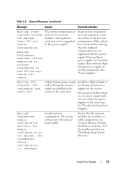
... cards may not be supported by the power supplies. See "Power Supplies." Check PSU. Unsupported memory configuration detected. The recommended memory configuration is not optimal. The system configuration of the same type. If any system components were just upgraded, return the system to meet PSU wattage. A High Output power supply Install two High...
... cards may not be supported by the power supplies. See "Power Supplies." Check PSU. Unsupported memory configuration detected. The recommended memory configuration is not optimal. The system configuration of the same type. If any system components were just upgraded, return the system to meet PSU wattage. A High Output power supply Install two High...
Hardware Owner's Manual
Page 58
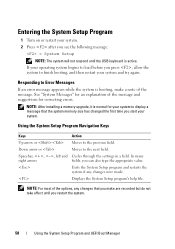
... Program and UEFI Boot Manager If your operating system begins to load before you press , allow the system to the previous field. NOTE: After installing a memory upgrade, it is normal for correcting errors. Down arrow or Moves to display a message that you make are recorded but do not take effect until the...
... Program and UEFI Boot Manager If your operating system begins to load before you press , allow the system to the previous field. NOTE: After installing a memory upgrade, it is normal for correcting errors. Down arrow or Moves to display a message that you make are recorded but do not take effect until the...
Hardware Owner's Manual
Page 131
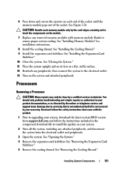
...connect the system to the electrical outlet. 13 Turn on your system. 2 Turn off the system, including any removed memory modules with the product. 1 Prior to upgrading your system, download the latest system BIOS version from the electrical outlet and peripherals. 3 Open the system. See "... touch the components on the module. 7 Replace any attached peripherals, and disconnect the system from support.dell.com and follow the safety instructions that is not authorized by Dell is not covered by a certified service technician. See "Removing the Cooling Shroud." CAUTION: Handle each end...
...connect the system to the electrical outlet. 13 Turn on your system. 2 Turn off the system, including any removed memory modules with the product. 1 Prior to upgrading your system, download the latest system BIOS version from the electrical outlet and peripherals. 3 Open the system. See "... touch the components on the module. 7 Replace any attached peripherals, and disconnect the system from support.dell.com and follow the safety instructions that is not authorized by Dell is not covered by a certified service technician. See "Removing the Cooling Shroud." CAUTION: Handle each end...
Hardware Owner's Manual
Page 202
... power indicators, 12, 21 power supplies indicators, 21 installing, 89 removing, 88 troubleshooting, 160 power supply blank, 90 processor installing, 134 removing, 131 troubleshooting, 173 upgrades, 131 PSU See power supply. N NIC hardware key, 106 NICs connectors, 20 indicators, 24 troubleshooting, 157 O opening the system, 80 optical drive installing, 109 removing...
... power indicators, 12, 21 power supplies indicators, 21 installing, 89 removing, 88 troubleshooting, 160 power supply blank, 90 processor installing, 134 removing, 131 troubleshooting, 173 upgrades, 131 PSU See power supply. N NIC hardware key, 106 NICs connectors, 20 indicators, 24 troubleshooting, 157 O opening the system, 80 optical drive installing, 109 removing...
Hardware Owner's Manual
Page 204
...damaged system, 159 expansion cards, 171 external connections, 155 hard drive, 169 internal SD card, 165 internal USB key, 166 keyboard, 156 memory, 163 NIC, 157 optical drive, 167 power supplies, 160 processor, 173 storage controller card, 170 system cooling, 161 system startup failure, ...70 main screen, 71 System Utilities screen, 71 UEFI Boot Settings screen, 71 UEFI boot mode, 57 upgrades processor, 131 USB back-panel connectors, 20 front-panel connectors, 12 USB memory key installing, 102 removing, 102 troubleshooting, 166 V VFlash SD card installing, 106 video connector, 20 ...
...damaged system, 159 expansion cards, 171 external connections, 155 hard drive, 169 internal SD card, 165 internal USB key, 166 keyboard, 156 memory, 163 NIC, 157 optical drive, 167 power supplies, 160 processor, 173 storage controller card, 170 system cooling, 161 system startup failure, ...70 main screen, 71 System Utilities screen, 71 UEFI Boot Settings screen, 71 UEFI boot mode, 57 upgrades processor, 131 USB back-panel connectors, 20 front-panel connectors, 12 USB memory key installing, 102 removing, 102 troubleshooting, 166 V VFlash SD card installing, 106 video connector, 20 ...


