
Hardware Owner's Manual
Page 79
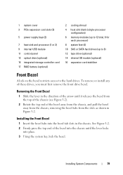
... place. 3 Using the system key, lock the bezel. See Figure 3-2. 2 Firmly press the top end of the bezel into the chassis until it releases the bezel from the top of the chassis (see Figure 3-2). 2 Rotate the top end of these drives, you must first remove the front drive bezel. Installing System Components... SATA hard drives (up to 8) 12 tape drive (optional) 14 internal SD module (optional) 16 expansion card stabilizer Front Bezel A lock on the bezel restricts access to the hard drives.
... place. 3 Using the system key, lock the bezel. See Figure 3-2. 2 Firmly press the top end of the bezel into the chassis until it releases the bezel from the top of the chassis (see Figure 3-2). 2 Rotate the top end of these drives, you must first remove the front drive bezel. Installing System Components... SATA hard drives (up to 8) 12 tape drive (optional) 14 internal SD module (optional) 16 expansion card stabilizer Front Bezel A lock on the bezel restricts access to the hard drives.
Hardware Owner's Manual
Page 103
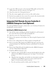
...Media (Optional)." 7 Install the iDRAC6 Enterprise card: a Angle the card so that the RJ-45 connector fits through the hole in the chassis for the hole location. See Figure 6-1 for the location of advanced features for the port location. 6 Remove the VFlash SD card (if ...installed) from the system back panel. Integrated Dell Remote Access Controller 6 (iDRAC6) Enterprise Card (Optional) The optional iDRAC6 Enterprise card provides a set of the connector. See "Opening the System." 3 Remove...
...Media (Optional)." 7 Install the iDRAC6 Enterprise card: a Angle the card so that the RJ-45 connector fits through the hole in the chassis for the hole location. See Figure 6-1 for the location of advanced features for the port location. 6 Remove the VFlash SD card (if ...installed) from the system back panel. Integrated Dell Remote Access Controller 6 (iDRAC6) Enterprise Card (Optional) The optional iDRAC6 Enterprise card provides a set of the connector. See "Opening the System." 3 Remove...
Hardware Owner's Manual
Page 139
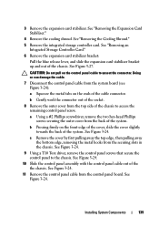
...." 6 Remove the expansion card stabilizer bracket: Pull the blue release lever, and slide the expansion card stabilizer bracket up and out of the the chassis. a Using a #2 Phillips screwdriver, remove the two hex-head Phillips screws securing the outer cover from the top side of the cable connector....T10 Torx driver, remove the control panel screws that secure the control panel to access the remaining control panel screw. See Figure 3-24. 10 Slide the control panel assembly with the control panel cable out of the chassis. b Gently work the connector out of the socket. 8 Remove the outer...
...." 6 Remove the expansion card stabilizer bracket: Pull the blue release lever, and slide the expansion card stabilizer bracket up and out of the the chassis. a Using a #2 Phillips screwdriver, remove the two hex-head Phillips screws securing the outer cover from the top side of the cable connector....T10 Torx driver, remove the control panel screws that secure the control panel to access the remaining control panel screw. See Figure 3-24. 10 Slide the control panel assembly with the control panel cable out of the chassis. b Gently work the connector out of the socket. 8 Remove the outer...


