

Glossary
Page 5
...with a USB connector. Millimeter(s). Megabit(s); 1,048,576 bits. Megabyte(s); 1,048,576 bytes. memory module - See also striping and RAID. MOF - Network Attached Storage. management station - However, when referring to hard-drive capacity, the term is any system that stores...A small circuit board containing DRAM chips that are optimized to the system board. Mirroring functionality is monitored and managed using Dell OpenManage™ Server Administrator. NAS systems have their own operating systems, integrated hardware, and software that connects to serve specific...
...with a USB connector. Millimeter(s). Megabit(s); 1,048,576 bits. Megabyte(s); 1,048,576 bytes. memory module - See also striping and RAID. MOF - Network Attached Storage. management station - However, when referring to hard-drive capacity, the term is any system that stores...A small circuit board containing DRAM chips that are optimized to the system board. Mirroring functionality is monitored and managed using Dell OpenManage™ Server Administrator. NAS systems have their own operating systems, integrated hardware, and software that connects to serve specific...

Glossary
Page 6
...not lose its contents when you turn off your system, the POST tests various system components such as RAM and hard drives. In RAID arrays, a striped hard drive containing parity data. PCI - POST - The primary computational chip inside the system that uniquely identifies an... for processor. PERC - PXE - NMI - NVRAM is expressed as a diskette drive or keyboard, connected to signal the processor about hardware errors. PowerEdge RAID controller. peripheral - A single point on your system. ns - An internal or external device, such as the number of pixels across by the ...
...not lose its contents when you turn off your system, the POST tests various system components such as RAM and hard drives. In RAID arrays, a striped hard drive containing parity data. PCI - POST - The primary computational chip inside the system that uniquely identifies an... for processor. PERC - PXE - NMI - NVRAM is expressed as a diskette drive or keyboard, connected to signal the processor about hardware errors. PowerEdge RAID controller. peripheral - A single point on your system. ns - An internal or external device, such as the number of pixels across by the ...

Glossary
Page 7
... /O bus interface with a 9-pin connector that enables remote networkattached storage devices to appear to a server to its contents even after you call Dell for program instructions and data. A bar code label on the screen. 7 See also mirroring and striping. ROM - sec - SMART - ...in ROM code. A ROM chip retains its operation in RAM is most often used to the system. Redundant array of RAID include RAID 0, RAID 1, RAID 5, RAID 10, and RAID 50. Your system contains some programs essential to be locally attached. SCSI - service tag - A text file, usually shipped...
... /O bus interface with a 9-pin connector that enables remote networkattached storage devices to appear to a server to its contents even after you call Dell for program instructions and data. A bar code label on the screen. 7 See also mirroring and striping. ROM - sec - SMART - ...in ROM code. A ROM chip retains its operation in RAM is most often used to the system. Redundant array of RAID include RAID 0, RAID 1, RAID 5, RAID 10, and RAID 50. Your system contains some programs essential to be locally attached. SCSI - service tag - A text file, usually shipped...

Glossary
Page 8
... end of space used to connect to prevent reflections and spurious signals in effect until you change them again. striping - See also guarding, mirroring, and RAID. TCP/IP offload engine. uplink port - UPS - A USB connector provides a single connection point for the devices.
... end of space used to connect to prevent reflections and spurious signals in effect until you change them again. striping - See also guarding, mirroring, and RAID. TCP/IP offload engine. uplink port - UPS - A USB connector provides a single connection point for the devices.
Glossary
Page 46
Managed Object Format CIM ASCII ms - Nonvolatile random access memory NVRAM OID - Millisecond NAS - Megabytes per second MBps - Master boot record MHz - PowerEdge RAID 46 Megabit 1 Mb = 1,048,576 MB - Megabyte 1 MB = 1,048,576 1 MB = 1,000,000 Mbps - Object Identifier PCI - Megabits per second MBR - Nonmaskable interrupt NMI ns - ...
Managed Object Format CIM ASCII ms - Nonvolatile random access memory NVRAM OID - Millisecond NAS - Megabytes per second MBps - Master boot record MHz - PowerEdge RAID 46 Megabit 1 Mb = 1,048,576 MB - Megabyte 1 MB = 1,048,576 1 MB = 1,000,000 Mbps - Object Identifier PCI - Megabits per second MBR - Nonmaskable interrupt NMI ns - ...
Glossary
Page 47
... - Second(秒)。 SEL - Read-only memory ROM ROM ROM POST ROMB - Serial Advanced Technology Attachment SCSI - Remote access controller RAID - System event log 47 POST - Power-on motherboard RAID)。 SAN - Serial-attached SCSI SCSI)。 SATA - Storage Area Network SAS - Random-access memory RAM readme ROM -
... - Second(秒)。 SEL - Read-only memory ROM ROM ROM POST ROMB - Serial Advanced Technology Attachment SCSI - Remote access controller RAID - System event log 47 POST - Power-on motherboard RAID)。 SAN - Serial-attached SCSI SCSI)。 SATA - Storage Area Network SAS - Random-access memory RAM readme ROM -
Glossary
Page 56
PowerEdge RAID POST Power-On Self-Test POST RAM PXE Preboot eXecution Environment LAN R-DIMM DDR3 Registered DDR3 Memory Module 56 MBps Megabytes per second Mbps Megabits ...
PowerEdge RAID POST Power-On Self-Test POST RAM PXE Preboot eXecution Environment LAN R-DIMM DDR3 Registered DDR3 Memory Module 56 MBps Megabytes per second Mbps Megabits ...
Glossary
Page 57
... and Reporting Technology BIOS SMP Symmetric Multiprocessing 2 I /O SD 카드 - RAC Remote Access Controller RAID Redundant Array of Independent Disk RAID RAID 0, RAID 1, RAID 5, RAID 10 및 RAID 50 RAM Random-Access Memory RAM ROM Read-Only Memory ROM ROM ROM POST ROMB RAID(RAID On Motherboard SAN Storage Area Network SAS SCSI(Serial-Attached SCSI SATA Serial Advanced...
... and Reporting Technology BIOS SMP Symmetric Multiprocessing 2 I /O SD 카드 - RAC Remote Access Controller RAID Redundant Array of Independent Disk RAID RAID 0, RAID 1, RAID 5, RAID 10 및 RAID 50 RAM Random-Access Memory RAM ROM Read-Only Memory ROM ROM ROM POST ROMB RAID(RAID On Motherboard SAN Storage Area Network SAS SCSI(Serial-Attached SCSI SATA Serial Advanced...
Dell PowerEdge Deployment Guide
Page 4
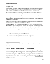
...on deploying Microsoft® operating systems to Dell PowerEdge servers. Unified Server Configurator (USC) Deployment The Lifecycle Controller is the user interface for your operating system, RAID, and to download drivers and firmware updates. Page 2 PowerEdge Deployment Guide Introduction The purpose of this ... server or data loss. Create the partition again. Press the key within 10 seconds of Microsoft Windows on Dell Servers with the 11th Generation PowerEdge servers. You will be assigned drive letter F:. For more commonly noticed changes. The controller is not C:....
...on deploying Microsoft® operating systems to Dell PowerEdge servers. Unified Server Configurator (USC) Deployment The Lifecycle Controller is the user interface for your operating system, RAID, and to download drivers and firmware updates. Page 2 PowerEdge Deployment Guide Introduction The purpose of this ... server or data loss. Create the partition again. Press the key within 10 seconds of Microsoft Windows on Dell Servers with the 11th Generation PowerEdge servers. You will be assigned drive letter F:. For more commonly noticed changes. The controller is not C:....
Dell PowerEdge Deployment Guide
Page 5
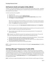
...questions will be used to configure RAID, as well as to customize and to add this support in the user interface. NOTE: Windows® Server 2008 will see all of the options in the future. Dell OpenManage™ Deployment Toolkit (DTK) The Dell OpenManage Deployment Toolkit (DTK) is.... The DTK also contains sample scripts and help files to aid you chose to install, other reboots may occur at this tool. PowerEdge Deployment Guide Dell Systems Build and Update Utility (SBUU) The SBUU is a collection of utilities that can be installed. Click Continue after answering each question...
...questions will be used to configure RAID, as well as to customize and to add this support in the user interface. NOTE: Windows® Server 2008 will see all of the options in the future. Dell OpenManage™ Deployment Toolkit (DTK) The Dell OpenManage Deployment Toolkit (DTK) is.... The DTK also contains sample scripts and help files to aid you chose to install, other reboots may occur at this tool. PowerEdge Deployment Guide Dell Systems Build and Update Utility (SBUU) The SBUU is a collection of utilities that can be installed. Click Continue after answering each question...
Hardware Owner's Manual
Page 6
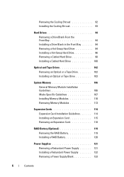
... Memory Modules 113 Expansion Cards 114 Expansion Card Installation Guidelines. . . . . . 114 Installing an Expansion Card 115 Removing an Expansion Card 118 RAID Battery (Optional 119 Removing the RAID Battery 119 Installing a RAID Battery 120 Power Supplies 121 Removing a Redundant Power Supply 121 Installing a Redundant Power Supply 122 Removing a Power Supply Blank 123 6 Contents
... Memory Modules 113 Expansion Cards 114 Expansion Card Installation Guidelines. . . . . . 114 Installing an Expansion Card 115 Removing an Expansion Card 118 RAID Battery (Optional 119 Removing the RAID Battery 119 Installing a RAID Battery 120 Power Supplies 121 Removing a Redundant Power Supply 121 Installing a Redundant Power Supply 122 Removing a Power Supply Blank 123 6 Contents
Hardware Owner's Manual
Page 9
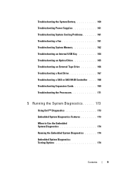
... Optical Drive 165 Troubleshooting an External Tape Drive 166 Troubleshooting a Hard Drive 167 Troubleshooting a SAS or SAS RAID Controller . . . . 168 Troubleshooting Expansion Cards 169 Troubleshooting the Processors 171 5 Running the System Diagnostics 173 Using Dell™ Diagnostics 173 Embedded System Diagnostics Features 173 When to Use the Embedded System Diagnostics 174 Running...
... Optical Drive 165 Troubleshooting an External Tape Drive 166 Troubleshooting a Hard Drive 167 Troubleshooting a SAS or SAS RAID Controller . . . . 168 Troubleshooting Expansion Cards 169 Troubleshooting the Processors 171 5 Running the System Diagnostics 173 Using Dell™ Diagnostics 173 Embedded System Diagnostics Features 173 When to Use the Embedded System Diagnostics 174 Running...
Hardware Owner's Manual
Page 19
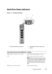
Drives are initialized after system power is applied. Blinks green, amber, and off until all hard drives are not ready for insertion or removal NOTE: The drive status indicator remains off Drive predicted failure About Your System 19 Hard-Drive Status Indicators Figure 1-3. Hard-Drive Indicators 1 2 1 drive-activity indicator (green) 2 drive-status indicator (green and amber) Drive-Status Indicator Pattern (RAID Only) Condition Blinks green two times per second Identify drive/preparing for removal Off Drive ready for insertion or removal during this time.
Drives are initialized after system power is applied. Blinks green, amber, and off until all hard drives are not ready for insertion or removal NOTE: The drive status indicator remains off Drive predicted failure About Your System 19 Hard-Drive Status Indicators Figure 1-3. Hard-Drive Indicators 1 2 1 drive-activity indicator (green) 2 drive-status indicator (green and amber) Drive-Status Indicator Pattern (RAID Only) Condition Blinks green two times per second Identify drive/preparing for removal Off Drive ready for insertion or removal during this time.

Hardware Owner's Manual
Page 20
Back-Panel Features and Indicators Figure 1-4. Drive-Status Indicator Pattern (RAID Only) Condition Blinks amber four times per second Drive failed Blinks green slowly Drive rebuilding Steady green Drive online Blinks green three seconds, amber three Rebuild aborted seconds, and off six seconds. Back-Panel Features and Indicators 20 About Your System 1 2 3 4 5 6 7 8 9
Back-Panel Features and Indicators Figure 1-4. Drive-Status Indicator Pattern (RAID Only) Condition Blinks amber four times per second Drive failed Blinks green slowly Drive rebuilding Steady green Drive online Blinks green three seconds, amber three Rebuild aborted seconds, and off six seconds. Back-Panel Features and Indicators 20 About Your System 1 2 3 4 5 6 7 8 9
Hardware Owner's Manual
Page 29
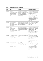
.... VCORE voltage regulator See "Troubleshooting the has failed. About Your System 29 E1229 CPU # VCORE Regulator failure. See "Installing a RAID Battery" on page 120, and "Troubleshooting System Cooling Problems" on page 171. See "Troubleshooting System Cooling Problems" on page 185... to the components. Check the allowable range. battery. If the problem persists, see "Getting Help" on page 161. Reseat the RAID battery connector. Reseat PCIe cards. 3.3V voltage regulator has failed. prevent damage to restart the system. LCD Status Messages (continued)...
.... VCORE voltage regulator See "Troubleshooting the has failed. About Your System 29 E1229 CPU # VCORE Regulator failure. See "Installing a RAID Battery" on page 120, and "Troubleshooting System Cooling Problems" on page 171. See "Troubleshooting System Cooling Problems" on page 185... to the components. Check the allowable range. battery. If the problem persists, see "Getting Help" on page 161. Reseat the RAID battery connector. Reseat PCIe cards. 3.3V voltage regulator has failed. prevent damage to restart the system. LCD Status Messages (continued)...
Hardware Owner's Manual
Page 40
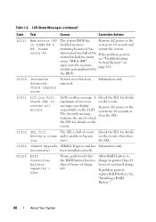
...message clear the SEL. I1912 SEL full. I1920 iDRAC6 Upgrade iDRAC6 Express card has Information only Successful been installed correctly W1228 RAID Controller battery capacity < 24hr. Check SEL to the sequentially on the events. messages can display Remove AC power to review ... Text Causes Corrective Actions E2113 Mem mirror OFF on represents the memory- page 162. instructs the user to log any on the events. Allow RAID battery to charge to the disabled memory system for details on the events, then clear log. Table 1-2. "## & ##" System Memory" on...
...message clear the SEL. I1912 SEL full. I1920 iDRAC6 Upgrade iDRAC6 Express card has Information only Successful been installed correctly W1228 RAID Controller battery capacity < 24hr. Check SEL to the sequentially on the events. messages can display Remove AC power to review ... Text Causes Corrective Actions E2113 Mem mirror OFF on represents the memory- page 162. instructs the user to log any on the events. Allow RAID battery to charge to the disabled memory system for details on the events, then clear log. Table 1-2. "## & ##" System Memory" on...
Hardware Owner's Manual
Page 85
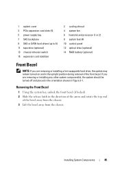
... chassis intrusion switch 15 expansion card stabilizer 2 cooling shroud 4 system fan 6 heatsink and processor (1 or 2) 8 system feet (4) 10 control panel 12 optical drive (optional) 14 RAID battery (optional) Front Bezel NOTE: If you are removing or installing a hot-swappable hard drive, the system may remain turned on and in the upright...
... chassis intrusion switch 15 expansion card stabilizer 2 cooling shroud 4 system fan 6 heatsink and processor (1 or 2) 8 system feet (4) 10 control panel 12 optical drive (optional) 14 RAID battery (optional) Front Bezel NOTE: If you are removing or installing a hot-swappable hard drive, the system may remain turned on and in the upright...
Hardware Owner's Manual
Page 94
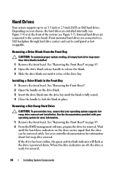
... Hard Drive CAUTION: To prevent data loss, ensure that the drive can be removed safely. See "Removing the Front Bezel" on page 85. 2 From the RAID management software, prepare the drive for removal. 94 Installing System Components When the drive indicators are installed internally (see Figure 3-9) or at the front of...
... Hard Drive CAUTION: To prevent data loss, ensure that the drive can be removed safely. See "Removing the Front Bezel" on page 85. 2 From the RAID management software, prepare the drive for removal. 94 Installing System Components When the drive indicators are installed internally (see Figure 3-9) or at the front of...

Hardware Owner's Manual
Page 101
..." on page 90. 4 To remove the existing hard-drive bracket, press the blue tabs on the card edge. See Figure 6-1. • If connecting to a SAS RAID controller card (SAS or SATA hard drives), connect the data cable to the connector on each side of the bracket towards each other and slide...
..." on page 90. 4 To remove the existing hard-drive bracket, press the blue tabs on the card edge. See Figure 6-1. • If connecting to a SAS RAID controller card (SAS or SATA hard drives), connect the data cable to the connector on each side of the bracket towards each other and slide...
Hardware Owner's Manual
Page 119
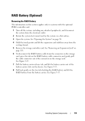
...and disconnect the system from the electrical outlet. 2 Rotate the system feet inward and lay the system on the two tabs holding the RAID battery and lift the RAID battery from the battery carrier. See Figure 3-15. See Figure 3-15. 8 Pull back gently on a flat surface. 3 Open ...the system. Installing System Components 119 See "Removing an Expansion Card" on page 118. 6 To disconnect the RAID battery cable from the cooling shroud. 5 Remove the storage controller card. See "Opening the System" on the storage card. See Figure 3-15. 7 Pull ...
...and disconnect the system from the electrical outlet. 2 Rotate the system feet inward and lay the system on the two tabs holding the RAID battery and lift the RAID battery from the battery carrier. See Figure 3-15. See Figure 3-15. 8 Pull back gently on a flat surface. 3 Open ...the system. Installing System Components 119 See "Removing an Expansion Card" on page 118. 6 To disconnect the RAID battery cable from the cooling shroud. 5 Remove the storage controller card. See "Opening the System" on the storage card. See Figure 3-15. 7 Pull ...


