
Glossary
Page 9
... capabilities). VDC - The amount of video memory installed primarily influences the number of pixels across multiple environments. WH - VAC - The logical circuitry that plugs into the system board or may be integrated into an expansion slot. A video adapter may be an expansion card... that provides (in addition to manage system resources-memory, disk drives, or printers, for example. A program used to your system's RAM. Watt(s)....
... capabilities). VDC - The amount of video memory installed primarily influences the number of pixels across multiple environments. WH - VAC - The logical circuitry that plugs into the system board or may be integrated into an expansion slot. A video adapter may be an expansion card... that provides (in addition to manage system resources-memory, disk drives, or printers, for example. A program used to your system's RAM. Watt(s)....
Getting Started Guide
Page 10
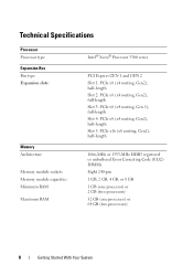
... Processor Processor type Expansion Bus Bus type Expansion slots: Memory Architecture Memory module sockets Memory module capacities Minimum RAM Maximum RAM Intel® Xeon® Processor 5500 series PCI Express GEN 1 and GEN 2 Slot 1: PCIe x8 (x4 routing, Gen2), half-length Slot 2: PCIe x8 (x4 routing, Gen2), full-length Slot 3: PCIe x8 (x4 routing, Gen 1), full-length...
... Processor Processor type Expansion Bus Bus type Expansion slots: Memory Architecture Memory module sockets Memory module capacities Minimum RAM Maximum RAM Intel® Xeon® Processor 5500 series PCI Express GEN 1 and GEN 2 Slot 1: PCIe x8 (x4 routing, Gen2), half-length Slot 2: PCIe x8 (x4 routing, Gen2), full-length Slot 3: PCIe x8 (x4 routing, Gen 1), full-length...
Hardware Owner's Manual
Page 21
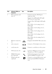
...connectors. Item Indicator, Button, or Icon Connector 1 PCIe expansion card slots (5) 2 Ethernet connectors (2) 3 video connector 4 serial connector 5 USB connectors (4) 6 iDRAC6 Enterprise port (optional) 7 VFlash media slot (optional) Description Connects up to the system. Connects a serial device... to five PCI Express expansion cards. Dedicated management port for the optional iDRAC6 Enterprise card. Connects USB devices to the system. Connects an external SD memory card...
...connectors. Item Indicator, Button, or Icon Connector 1 PCIe expansion card slots (5) 2 Ethernet connectors (2) 3 video connector 4 serial connector 5 USB connectors (4) 6 iDRAC6 Enterprise port (optional) 7 VFlash media slot (optional) Description Connects up to the system. Connects a serial device... to five PCI Express expansion cards. Dedicated management port for the optional iDRAC6 Enterprise card. Connects USB devices to the system. Connects an external SD memory card...
Hardware Owner's Manual
Page 39
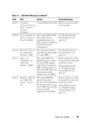
... 162. Check screen message. and will not log anymore If the problem persists, SBEs until the system is see "Troubleshooting memory module System Memory" on implicated by the BIOS. the memory had a multi- Table 1-2. slot "##" has had too many If the problem persists, errors. The system BIOS has Remove AC power to The system...
... 162. Check screen message. and will not log anymore If the problem persists, SBEs until the system is see "Troubleshooting memory module System Memory" on implicated by the BIOS. the memory had a multi- Table 1-2. slot "##" has had too many If the problem persists, errors. The system BIOS has Remove AC power to The system...
Hardware Owner's Manual
Page 45
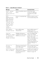
...been cleared. Restart the system and re-enter the BIOS settings. messages for possible causes. Memory modules are required but not installed in the clear setting. If problem persists, see "Getting...take the system mode. About Your System 45 attempt failed. Install memory modules for jumper location. See "System Memory" on page 61. MANUFACTURING MODE will be If not an ... The processor speed may be cleared before the next boot. CPU x installed with no memory. System reboot required for check any other system reboot. System fatal error during previous boot...
...been cleared. Restart the system and re-enter the BIOS settings. messages for possible causes. Memory modules are required but not installed in the clear setting. If problem persists, see "Getting...take the system mode. About Your System 45 attempt failed. Install memory modules for jumper location. See "System Memory" on page 61. MANUFACTURING MODE will be If not an ... The processor speed may be cleared before the next boot. CPU x installed with no memory. System reboot required for check any other system reboot. System fatal error during previous boot...
Hardware Owner's Manual
Page 47
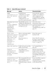
...Device Failure. An invalid system configuration caused a system halt. dedicated storage controller slot. Remove the PCIe expansion card and install the integrated storage controller in BIOS. Table 1-3. Invalid memory configuration on page 61. See Management "Troubleshooting a NIC" on page 156. ...Ensure that mouse and keyboard are installed in the slot! Gate A20 failure Faulty keyboard controller; See "Troubleshooting a USB Device" on Shared NIC= page 157. Ensure that the memory modules are securely attached to correct connectors. Invalid PCIe card ...
...Device Failure. An invalid system configuration caused a system halt. dedicated storage controller slot. Remove the PCIe expansion card and install the integrated storage controller in BIOS. Table 1-3. Invalid memory configuration on page 61. See Management "Troubleshooting a NIC" on page 156. ...Ensure that mouse and keyboard are installed in the slot! Gate A20 failure Faulty keyboard controller; See "Troubleshooting a USB Device" on Shared NIC= page 157. Ensure that the memory modules are securely attached to correct connectors. Invalid PCIe card ...
Hardware Owner's Manual
Page 52
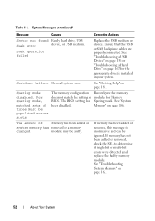
For sparing mode, matched sets of Memory has been added or system memory has removed or a memory changed module may be populated across slots. See "Troubleshooting System Memory" on page 185. Seek operation failed Replace the USB medium or device. Ensure that the USB or SAS backplane cables are properly connected. See "Getting ...
For sparing mode, matched sets of Memory has been added or system memory has removed or a memory changed module may be populated across slots. See "Troubleshooting System Memory" on page 185. Seek operation failed Replace the USB medium or device. Ensure that the USB or SAS backplane cables are properly connected. See "Getting ...

Hardware Owner's Manual
Page 53
...of ranks, or number of -day clock stopped Faulty battery or faulty chip. Memory" on x thermal sensor is installed in size: x,x,... See "Troubleshooting the System Battery" on page 106. Ensure that the memory modules are installed in rank count: x,x,... The following DIMMs should match in size... (continued) Message The following DIMMs should match in a valid configuration. The following DIMMs should match in geometry: x,x,... See "General Memory Module Installation Guidelines" on page 160. Table 1-3. See "System the specified memory slot. About Your System 53
...of ranks, or number of -day clock stopped Faulty battery or faulty chip. Memory" on x thermal sensor is installed in size: x,x,... See "Troubleshooting the System Battery" on page 106. Ensure that the memory modules are installed in rank count: x,x,... The following DIMMs should match in size... (continued) Message The following DIMMs should match in a valid configuration. The following DIMMs should match in geometry: x,x,... See "General Memory Module Installation Guidelines" on page 160. Table 1-3. See "System the specified memory slot. About Your System 53
Hardware Owner's Manual
Page 56
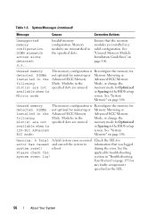
.... during the error. Invalid memory configuration. See "System Memory" on page 106. DIMM mismatch across slots detected: x,x,... Unused memory detected. See "System Memory" on page 106. Memory modules are installed in the specified slots. Table 1-3. See "General Memory Module Installation Guidelines" on page 155 for mirroring or Memory Mirroring or Advanced ECC Memory Advanced ECC Memory Mode. memory mode to Optimized or...
.... during the error. Invalid memory configuration. See "System Memory" on page 106. DIMM mismatch across slots detected: x,x,... Unused memory detected. See "System Memory" on page 106. Memory modules are installed in the specified slots. Table 1-3. See "General Memory Module Installation Guidelines" on page 155 for mirroring or Memory Mirroring or Advanced ECC Memory Advanced ECC Memory Mode. memory mode to Optimized or...

Hardware Owner's Manual
Page 107
... with the white release levers. • If memory modules with single- • For Memory Mirroring or Advanced ECC Mode, the socket furthest from the processor is unused and memory modules are installed beginning with socket A1 or B1...memory modules. Advanced ECC (Lockstep) Mode Support In this configuration, the two channels closest to the processor are installed, they will operate at the speed of memory module speed. • If quad-rank memory modules are allocated to 1067 MHz. - or dual-rank modules, the quad-rank modules must be installed in corresponding slots...
... with the white release levers. • If memory modules with single- • For Memory Mirroring or Advanced ECC Mode, the socket furthest from the processor is unused and memory modules are installed beginning with socket A1 or B1...memory modules. Advanced ECC (Lockstep) Mode Support In this configuration, the two channels closest to the processor are installed, they will operate at the speed of memory module speed. • If quad-rank memory modules are allocated to 1067 MHz. - or dual-rank modules, the quad-rank modules must be installed in corresponding slots...

Hardware Owner's Manual
Page 151
... time to cool before removing the system board. 12 Remove any loose cables away from the system board. 7 If applicable, remove all the memory modules and memory blanks. See "Removing the SAS Backplane" on the system board are free from system. c Lift the system board until the securing... slots on page 145. 14 Carefully route any installed heat sinks, processors and heat-sink blanks. Installing System Components 151 See "Opening the System" ...
... time to cool before removing the system board. 12 Remove any loose cables away from the system board. 7 If applicable, remove all the memory modules and memory blanks. See "Removing the SAS Backplane" on the system board are free from system. c Lift the system board until the securing... slots on page 145. 14 Carefully route any installed heat sinks, processors and heat-sink blanks. Installing System Components 151 See "Opening the System" ...

Hardware Owner's Manual
Page 153
... that came with the tabs on the chassis and lower the system board into the cutouts in the chassis. b Align the securing slots on the system board with the system. 1 Unpack the new system board and remove the label that is located on the processor shield... the connectors into the chassis. See "Installing a Processor" on page 91. See "Installing an Expansion Card" on page 135. 7 Replace all the memory modules and memory blanks. d Using a Phillips screwdriver, tighten the captive screw. 4 If applicable, replace the SAS backplane. See "Installing the System Fan" on page...
... that came with the tabs on the chassis and lower the system board into the cutouts in the chassis. b Align the securing slots on the system board with the system. 1 Unpack the new system board and remove the label that is located on the processor shield... the connectors into the chassis. See "Installing a Processor" on page 91. See "Installing an Expansion Card" on page 135. 7 Replace all the memory modules and memory blanks. d Using a Phillips screwdriver, tighten the captive screw. 4 If applicable, replace the SAS backplane. See "Installing the System Fan" on page...

Hardware Owner's Manual
Page 181
...slot 1) PCIe connector x4 (slot 2) PCIe connector x4 (slot 3) PCIe connector x4 (slot 4) PCIe connector x8 (slot 5) System fan connector Processor 2 iDRAC 6 Enterprise card connector Memory module slot B3 (white release lever) Memory module slot B2 (white release lever) Memory module slot B1 (white release lever) Memory module slot... pin power connector Processor 1 Backplane I2C connector Memory module slot A3 (white release lever) Memory module slot A2 (white release lever) Memory module slot A1 (white release lever) Memory module slot A4 Chassis intrusion switch connector Hard drive activity ...
...slot 1) PCIe connector x4 (slot 2) PCIe connector x4 (slot 3) PCIe connector x4 (slot 4) PCIe connector x8 (slot 5) System fan connector Processor 2 iDRAC 6 Enterprise card connector Memory module slot B3 (white release lever) Memory module slot B2 (white release lever) Memory module slot B1 (white release lever) Memory module slot... pin power connector Processor 1 Backplane I2C connector Memory module slot A3 (white release lever) Memory module slot A2 (white release lever) Memory module slot A1 (white release lever) Memory module slot A4 Chassis intrusion switch connector Hard drive activity ...
Hardware Owner's Manual
Page 196
... can display (with greater resolution and color display capabilities than previous standards. VAC - video adapter - video memory - video resolution - An unregistered (unbuffered) DDR3 memory module. A USB connector provides a single connection point for multiple USB-compliant devices, such as multiple virtual...may be integrated into an expansion slot. termination on these devices by changing jumper or switch settings on a network hub or switch used to manage system resources-memory, disk drives, or printers, for example. UPS - USB - See memory key. A program used to ...
... can display (with greater resolution and color display capabilities than previous standards. VAC - video adapter - video memory - video resolution - An unregistered (unbuffered) DDR3 memory module. A USB connector provides a single connection point for multiple USB-compliant devices, such as multiple virtual...may be integrated into an expansion slot. termination on these devices by changing jumper or switch settings on a network hub or switch used to manage system resources-memory, disk drives, or printers, for example. UPS - USB - See memory key. A program used to ...


