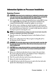
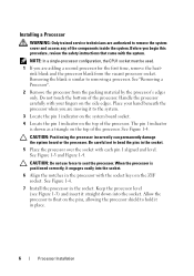
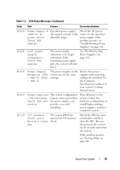
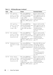
Information Update - Processor Installation
Page 3
...The heat sink is recommended that came with the system. 1 Prior to upgrading your system, download the latest system BIOS version from support.dell.com and follow the instructions included in the interior of stored power prior to removing the cover. When disconnected from the processor. 7 Release.... See your system. 2 Turn off of the processor and set the heat sink aside upside down . Before you begin this procedure, review the safety instructions that you intend to remove the system cover and access any attached peripherals, and disconnect the system from a processor unless ...
Information Update - Processor Installation
Page 6
... the pin 1 indicator on the top of the processor. NOTE: In a single-processor configuration, the CPU1 socket must be used. 1 If you begin this procedure, review the safety instructions that came with each pin 1 aligned and level. Do not touch the bottom of the processor. The pin 1 indicator is shown as...
Getting Started Guide
Page 5
Failure to extend the feet poses the risk of having the system tip over, possibly causing bodily injury or damage to help properly stabilize the system. Getting Started With Your System 3 Stabilizing the Tower System WARNING: The tower system has four feet on its bottom panel that came with the system. Installation and Configuration WARNING: Before performing the following procedure, review the safety instructions that can be extended outward to the system.
Hardware Owner's Manual
Page 33
.... About Your System 33 Table 1-2. See "Troubleshooting Power Supplies" on page 161. The system configuration requires more information and then clear the SEL. E1710 I /O channel Review & clear check. reported an I /O channel The system BIOS has check error. Check the SEL for the specified power supply. Remove AC power to the system...
Hardware Owner's Manual
Page 34
... reseat the reported a PCI parity error PCIe expansion cards. The system BIOS has Check the SEL for 10 seconds and restart the system. for more Review & clear determined there has been information and then SEL. If error on a component that the problem persists, see "Getting Help" on page 185. Remove is...
Hardware Owner's Manual
Page 35
... If the failure. E1A1D Control panel USB cable not detected. Check has been removed from drive. E1A14 SAS cable A SAS cable A is missing or bad. Review has experienced a fault. & clear SEL. USB cable to the control panel is missing or Reseat the cable. Information only. If the problem persists, see "Getting...
Hardware Owner's Manual
Page 38
... test See "Troubleshooting test failure. If the problem persists, see "Getting Help" on page 185. Check screen message. E2021 Incorrect Incorrect memory memory configuration. configuration. Review User Guide. Check screen for 10 seconds and restart the system. Check screen for 10 seconds and restart the system. Remove AC power to the...
Hardware Owner's Manual
Page 40
... If the problem persists, mirror has had too many see "Troubleshooting errors. The SEL is full of events Check the SEL for details Review & clear and is unable to review all Errors. I1920 iDRAC6 Upgrade iDRAC6 Express card has Information only Successful been installed correctly W1228 RAID Controller battery capacity < 24hr. Power...
Hardware Owner's Manual
Page 47
... each CPU should match. Ensure that mouse and keyboard are installed in the dedicated slot. page 185. NIC settings. Run the System Setup program and review the current settings. System Messages (continued) Message Causes Corrective Actions DIMM configuration on a dualprocessor system. Invalid PCIe card The system halted because found in the...
Hardware Owner's Manual
Page 83
... have cabled or hot-swappable hard drives, redundant or non-redundant power supplies, and an LCD panel or diagnostic indicators. The illustrations in this procedure, review the safety instructions that shipped with the system. Installing System Components 83
Hardware Owner's Manual
Page 90
... the cover release latch counterclockwise to lift the system by yourself. See Figure 3-5. 5 Grasp the cover on a flat surface. WARNING: Whenever you begin this procedure, review the safety instructions that came with the system.
Hardware Owner's Manual
Page 92
... trained service technicians are authorized to remove the system cover and access any peripherals and connect the system to cool before you begin this procedure, review the safety instructions that came with the cooling shroud removed. Ensure that the memory modules and heat sink have had sufficient time to an electrical...
Hardware Owner's Manual
Page 98
... Drive WARNING: Only trained service technicians are authorized to remove the system cover and access any components inside the system. Before you begin this procedure, review the safety instructions that came with the system. 1 Turn off the system and attached peripherals, and disconnect the system from the electrical outlet and from...
Hardware Owner's Manual
Page 100
Figure 3-10. Removing a Hard Drive From a Hard Drive Bracket 1 2 1 hard drive 2 hard drive bracket NOTE: If you begin this procedure, review the safety instructions that came with the system. 1 Turn off the system and attached peripherals, and disconnect the system from the electrical outlet and from ...
Hardware Owner's Manual
Page 102
... release latch in the direction of the arrow to an electrical outlet. 13 Turn on page 89. See Figure 3-12 7 If you begin this procedure, review the safety instructions that came with the system. 1 Turn off the system, including any attached peripherals, and disconnect the system from the back of the...
Hardware Owner's Manual
Page 103
... any of the components inside the system. You must have a SCSI controller card installed. If you are installing a SCSI tape drive, you begin this procedure, review the safety instructions that accompanied the drive.
Hardware Owner's Manual
Page 110
.... 2 Rotate the system feet inward and lay the system on the memory module. Requires x4- Remove memory-module blanks only if you begin this procedure, review the safety instructions that is not occupied. Table 3-2. Sample UDIMM Memory Configurations (Per Processor) Memory Mode Memory Module Size 4 Memory Sockets 12 3 Single Processor Physical...
Hardware Owner's Manual
Page 113
... and connect the system to an electrical outlet. 13 Turn on page 93. 9 Close the system. Install a memory-module blank if you begin this procedure, review the safety instructions that is not occupied. See Figure 6-1. 6 Press down . Allow time for the memory modules to ensure proper system cooling. See "Installing Memory...
Hardware Owner's Manual
Page 115
... cover from the cooling shroud. Filler brackets must be installed over empty expansion-card slots to secure the card in case you begin this procedure, review the safety instructions that the card's metal tab is inserted in proper cooling and airflow inside the system. See Figure 3-14. 8 If you are installing...
Hardware Owner's Manual
Page 118
... the touch points on the system and attached peripherals. 14 Remove the card's device driver from the expansion-card connector. 7 If you begin this procedure, review the safety instructions that came with the system. 1 Turn off the system, including any peripherals and connect the system to maintain Federal Communications Commission (FCC...