

Glossary
Page 1
...that allows the processor to communicate with MIB data from the hard drive. bootable media - Your system contains an expansion bus that contains a processor, memory, and a hard drive. Common Information Model describes the management information utilized by an ...Dell™ Glossary NOTE: For additional information on storage terminology, visit the Storage Networking Industry Association's website at www.snia.org and click on a regular basis. A - ACPI - Advanced Configuration and Power Interface. An individual code assigned to start your system's hard drive...
...that allows the processor to communicate with MIB data from the hard drive. bootable media - Your system contains an expansion bus that contains a processor, memory, and a hard drive. Common Information Model describes the management information utilized by an ...Dell™ Glossary NOTE: For additional information on storage terminology, visit the Storage Networking Industry Association's website at www.snia.org and click on a regular basis. A - ACPI - Advanced Configuration and Power Interface. An individual code assigned to start your system's hard drive...

Glossary
Page 3
... mode that uses the Internet SCSI protocol. hot-plug - Integrated Dell Remote Access Controller. A remote access controller that can be differentiated from computational activity. InfiniBand offers point-to insert or install a device, typically a hard drive or an internal cooling fan, into the host system while the ...board for connection of file storage. FTP - File transfer protocol. g - Gram(s). Gravities. Gb - However, when referring to hard-drive capacity, the term is an output device. host adapter - A controller that can optionally use a FAT file system structure. The...
... mode that uses the Internet SCSI protocol. hot-plug - Integrated Dell Remote Access Controller. A remote access controller that can be differentiated from computational activity. InfiniBand offers point-to insert or install a device, typically a hard drive or an internal cooling fan, into the host system while the ...board for connection of file storage. FTP - File transfer protocol. g - Gram(s). Gravities. Gb - However, when referring to hard-drive capacity, the term is an output device. host adapter - A controller that can optionally use a FAT file system structure. The...

Glossary
Page 5
...managed using Dell OpenManage™ Server Administrator. NIC - Your system's unique hardware number on a network. A managed system is any system that are optimized to a network. 5 management station - A system used for implementing shared storage on a network. However, when referring to hard-drive capacity,... the term is one or more managed systems from a central location. Master boot record. memory address - A type of data redundancy in which a set of physical drives stores data and one of the concepts ...
...managed using Dell OpenManage™ Server Administrator. NIC - Your system's unique hardware number on a network. A managed system is any system that are optimized to a network. 5 management station - A system used for implementing shared storage on a network. However, when referring to hard-drive capacity,... the term is one or more managed systems from a central location. Master boot record. memory address - A type of data redundancy in which a set of physical drives stores data and one of the concepts ...

Glossary
Page 6
... distribution unit. provider - Remote access controller. 6 A device sends an NMI to a system. Each partition can divide a hard drive into multiple physical sections called partitions with a block of booting a system via a LAN (without a hard drive or bootable diskette). PowerEdge RAID controller. processor - PXE - Preboot eXecution Environment. A power source with multiple power outlets that communicates with the...
... distribution unit. provider - Remote access controller. 6 A device sends an NMI to a system. Each partition can divide a hard drive into multiple physical sections called partitions with a block of booting a system via a LAN (without a hard drive or bootable diskette). PowerEdge RAID controller. processor - PXE - Preboot eXecution Environment. A power source with multiple power outlets that communicates with the...

Glossary
Page 7
... bar code label on the system used to connect a modem to the system BIOS and then display an error message on motherboard. Allows hard drives to report errors and failures to the system. See also mirroring and striping. The system's primary temporary storage area for technical support. Any... memory. SAS - service tag - A method of independent disks. read -only file is one bit at a time and is lost when you call Dell for program instructions and data. A read -only file - A ROM chip retains its operation in ROM include the program that you turn off your system...
... bar code label on the system used to connect a modem to the system BIOS and then display an error message on motherboard. Allows hard drives to report errors and failures to the system. See also mirroring and striping. The system's primary temporary storage area for technical support. Any... memory. SAS - service tag - A method of independent disks. read -only file is one bit at a time and is lost when you call Dell for program instructions and data. A read -only file - A ROM chip retains its operation in ROM include the program that you turn off your system...
Dell PowerEdge Deployment Guide
Page 4
... partition and press to install the operating system on the 9th and 10th Generation PowerEdge servers. NOTE: This same behavior may get assigned the drive letter C: and the actual hard drive will briefly cover some of the more information, see the Microsoft Knowledge Base article...See the Unified Server Configurator documentation on www.support.dell.com for Installation of Microsoft Windows on Dell Servers with the introduction of managed and persistent storage that the drive letter assigned is started, the hard drive will notice that embeds systems management features in addition...
... partition and press to install the operating system on the 9th and 10th Generation PowerEdge servers. NOTE: This same behavior may get assigned the drive letter C: and the actual hard drive will briefly cover some of the more information, see the Microsoft Knowledge Base article...See the Unified Server Configurator documentation on www.support.dell.com for Installation of Microsoft Windows on Dell Servers with the introduction of managed and persistent storage that the drive letter assigned is started, the hard drive will notice that embeds systems management features in addition...
Dell PowerEdge Deployment Guide
Page 5
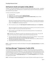
PowerEdge Deployment Guide Dell Systems Build and Update Utility (SBUU) The SBUU is a collection of the operating system installation process. 9) The operating system and required drivers should boot to the hard drive at this time. Click Continue after answering each question. 5) Select any options you... Management section, if searching for the SBUU documentation. SBUU will now prepare for BIOS Boot Manager. 3) Highlight the optical drive containing the Dell Systems Build and Update Utility and press . 4) Click Configure in the Server OS Installation. NOTE: Windows® Server ...
PowerEdge Deployment Guide Dell Systems Build and Update Utility (SBUU) The SBUU is a collection of the operating system installation process. 9) The operating system and required drivers should boot to the hard drive at this time. Click Continue after answering each question. 5) Select any options you... Management section, if searching for the SBUU documentation. SBUU will now prepare for BIOS Boot Manager. 3) Highlight the optical drive containing the Dell Systems Build and Update Utility and press . 4) Click Configure in the Server OS Installation. NOTE: Windows® Server ...
Dell PowerEdge Deployment Guide
Page 6
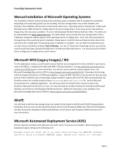
... may also use the latest RIS network driver for more information. This will be included, and therefore, the installation will fail since no hard drives will ensure that starting with ADS when two Intel™ Xeon™ processors are installing, the mass storage drivers may cause a problem.... support iSCSI and TOE. The utility allows you will need to provide the mass storage drivers from www.support.dell.com. For the 11th Generation PowerEdge servers, you to install the chipset, Broadcom NetXtreme II, and Matrox G200 video drivers. Microsoft Automated Deployment Service (...
... may also use the latest RIS network driver for more information. This will be included, and therefore, the installation will fail since no hard drives will ensure that starting with ADS when two Intel™ Xeon™ processors are installing, the mass storage drivers may cause a problem.... support iSCSI and TOE. The utility allows you will need to provide the mass storage drivers from www.support.dell.com. For the 11th Generation PowerEdge servers, you to install the chipset, Broadcom NetXtreme II, and Matrox G200 video drivers. Microsoft Automated Deployment Service (...

Deploying UEFI-Aware Operating Systems on Dell PowerEdge Servers
Page 9
...perspective, everything will contain support 3) General Linux support is used to interact with the hard drive directly (imaging tools) - UEFI uses GPT. DO NOT change the Boot Manager to support UEFI. Dell offers both legacy BIOS‐mode and UEFI‐mode. For a Microsoft Windows ...utility - Once the operating system is still an emerging technology and standard, so there are to the hard drive setup although this is not visible to UEFI, Dell recommends that may not work as BIOS‐mode installation. Deploying a UEFI‐Aware Operating System Once...
...perspective, everything will contain support 3) General Linux support is used to interact with the hard drive directly (imaging tools) - UEFI uses GPT. DO NOT change the Boot Manager to support UEFI. Dell offers both legacy BIOS‐mode and UEFI‐mode. For a Microsoft Windows ...utility - Once the operating system is still an emerging technology and standard, so there are to the hard drive setup although this is not visible to UEFI, Dell recommends that may not work as BIOS‐mode installation. Deploying a UEFI‐Aware Operating System Once...
Getting Started Guide
Page 11
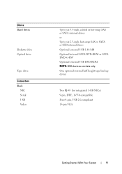
Drives Hard drives Diskette drive Optical drive Tape drive Connectors Back NIC Serial USB Video Up to six 3.5-inch, cabled or hot-swap SAS or SATA internal drives or Up to six 2.5-inch, hot-swap SAS or SATA or SSD internal drives Optional external USB 1.44-MB Optional internal SATA DVD-ROM or SATA DVD+/-RW Optional external USB DVD-ROM NOTE: DVD devices are data only. One optional internal half height tape backup device Two RJ-45 (for integrated 1-GB NICs) 9-pin, DTE, 16550-compatible Four 4-pin, USB 2.0-compliant 15-pin VGA Getting Started With Your System 9
Drives Hard drives Diskette drive Optical drive Tape drive Connectors Back NIC Serial USB Video Up to six 3.5-inch, cabled or hot-swap SAS or SATA internal drives or Up to six 2.5-inch, hot-swap SAS or SATA or SSD internal drives Optional external USB 1.44-MB Optional internal SATA DVD-ROM or SATA DVD+/-RW Optional external USB DVD-ROM NOTE: DVD devices are data only. One optional internal half height tape backup device Two RJ-45 (for integrated 1-GB NICs) 9-pin, DTE, 16550-compatible Four 4-pin, USB 2.0-compliant 15-pin VGA Getting Started With Your System 9

Hardware Owner's Manual
Page 3
Contents 1 About Your System 11 Accessing System Features During Startup 11 Front-Panel Features and Indicators 12 LCD Panel Features (Optional 15 Home Screen 16 Setup Menu 17 View Menu 18 Hard-Drive Status Indicators 19 Back-Panel Features and Indicators 20 Guidelines for Connecting External Devices 22 NIC Indicator Codes 23 Power Indicator Codes 23 Diagnostic Lights (Optional 26 LCD Status Messages (Optional 28 Solving Problems Described by LCD Status Messages 41 Removing LCD Status Messages 41 System Messages 42 Warning Messages 58 Diagnostics Messages 59 Contents 3
Contents 1 About Your System 11 Accessing System Features During Startup 11 Front-Panel Features and Indicators 12 LCD Panel Features (Optional 15 Home Screen 16 Setup Menu 17 View Menu 18 Hard-Drive Status Indicators 19 Back-Panel Features and Indicators 20 Guidelines for Connecting External Devices 22 NIC Indicator Codes 23 Power Indicator Codes 23 Diagnostic Lights (Optional 26 LCD Status Messages (Optional 28 Solving Problems Described by LCD Status Messages 41 Removing LCD Status Messages 41 System Messages 42 Warning Messages 58 Diagnostics Messages 59 Contents 3
Hardware Owner's Manual
Page 6
... 92 Installing the Cooling Shroud 93 Hard Drives 94 Removing a Drive Blank From the Front Bay 94 Installing a Drive Blank in the Front Bay 94 Removing a Hot-Swap Hard Drive 94 Installing a Hot-Swap Hard Drive 96 Removing a Cabled Hard Drive 98 Installing a Cabled Hard Drive 100 Optical and Tape Drives 102 Removing an Optical or a Tape Drive 102 Installing an Optical or Tape...
... 92 Installing the Cooling Shroud 93 Hard Drives 94 Removing a Drive Blank From the Front Bay 94 Installing a Drive Blank in the Front Bay 94 Removing a Hot-Swap Hard Drive 94 Installing a Hot-Swap Hard Drive 96 Removing a Cabled Hard Drive 98 Installing a Cabled Hard Drive 100 Optical and Tape Drives 102 Removing an Optical or a Tape Drive 102 Installing an Optical or Tape...
Hardware Owner's Manual
Page 9
... a Fan 161 Troubleshooting System Memory 162 Troubleshooting an Internal USB Key 164 Troubleshooting an Optical Drive 165 Troubleshooting an External Tape Drive 166 Troubleshooting a Hard Drive 167 Troubleshooting a SAS or SAS RAID Controller . . . . 168 Troubleshooting Expansion Cards ...169 Troubleshooting the Processors 171 5 Running the System Diagnostics 173 Using Dell™ Diagnostics 173 Embedded System...
... a Fan 161 Troubleshooting System Memory 162 Troubleshooting an Internal USB Key 164 Troubleshooting an Optical Drive 165 Troubleshooting an External Tape Drive 166 Troubleshooting a Hard Drive 167 Troubleshooting a SAS or SAS RAID Controller . . . . 168 Troubleshooting Expansion Cards ...169 Troubleshooting the Processors 171 5 Running the System Diagnostics 173 Using Dell™ Diagnostics 173 Embedded System...

Hardware Owner's Manual
Page 12
Figure 1-1. Connects USB devices to the system. The ports are USB 2.0-compliant. 12 About Your System Front-Panel Features and Indicators NOTE: Depending on the configuration, your system may have an LCD panel or LED diagnostic indicators. Front Panel Features and Indicators 7 6 5 8 4 3 9 2 1 10 Item Indicator, Button, or Icon Connector 1 Front bezel 2 USB connectors (2) Description Covers the system's front-loading hard drives. The illustration in this section shows a system with an LCD panel.
Figure 1-1. Connects USB devices to the system. The ports are USB 2.0-compliant. 12 About Your System Front-Panel Features and Indicators NOTE: Depending on the configuration, your system may have an LCD panel or LED diagnostic indicators. Front Panel Features and Indicators 7 6 5 8 4 3 9 2 1 10 Item Indicator, Button, or Icon Connector 1 Front bezel 2 USB connectors (2) Description Covers the system's front-loading hard drives. The illustration in this section shows a system with an LCD panel.
Hardware Owner's Manual
Page 19
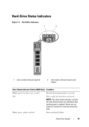
Hard-Drive Indicators 1 2 1 drive-activity indicator (green) 2 drive-status indicator (green and amber) Drive-Status Indicator Pattern (RAID Only) Condition Blinks green two times per second Identify drive/preparing for removal Off Drive ready for insertion or removal during this time. Blinks green, amber, and off until all hard drives are not ready for insertion or removal NOTE: The drive status indicator remains off Drive predicted failure About Your System 19 Drives are initialized after system power is applied. Hard-Drive Status Indicators Figure 1-3.
Hard-Drive Indicators 1 2 1 drive-activity indicator (green) 2 drive-status indicator (green and amber) Drive-Status Indicator Pattern (RAID Only) Condition Blinks green two times per second Identify drive/preparing for removal Off Drive ready for insertion or removal during this time. Blinks green, amber, and off until all hard drives are not ready for insertion or removal NOTE: The drive status indicator remains off Drive predicted failure About Your System 19 Drives are initialized after system power is applied. Hard-Drive Status Indicators Figure 1-3.
Hardware Owner's Manual
Page 27
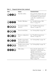
..."Getting Help" on page 162. Memory configuration See "Troubleshooting System error. Ensure that the diskette drive and hard drive are properly connected. About Your System 27 No memory modules detected. Memory" on page 185. Possible...Code (continued) Code Causes Hard drive failure. See Hard Drives for the appropriate drive installed in your system. Corrective Action Ensure that the diskette drive, optical drive, and hard drives are properly connected. Other failure. Table 1-1. See "Troubleshooting a USB Device" on the drives installed in your system. ...
..."Getting Help" on page 162. Memory configuration See "Troubleshooting System error. Ensure that the diskette drive and hard drive are properly connected. About Your System 27 No memory modules detected. Memory" on page 185. Possible...Code (continued) Code Causes Hard drive failure. See Hard Drives for the appropriate drive installed in your system. Corrective Action Ensure that the diskette drive, optical drive, and hard drives are properly connected. Other failure. Table 1-1. See "Troubleshooting a USB Device" on the drives installed in your system. ...

Hardware Owner's Manual
Page 35
LCD Status Messages (continued) Code Text Causes Corrective Actions E1810 Hard drive ## The specified hard drive fault. Check has been removed from drive. If the failure. Check bad. If the problem persists, see "Getting Help" on page 185. problem persists, ...Failed is bad. "Installing an iDRAC6 Express Card" on page 185. E1812 Hard drive ## The specified hard drive removed. If the failure. If the problem persists, see "Getting Help" on page 127. See "Troubleshooting a Hard Drive" on page 185. Information only. See the card is not installed properly or...
LCD Status Messages (continued) Code Text Causes Corrective Actions E1810 Hard drive ## The specified hard drive fault. Check has been removed from drive. If the failure. Check bad. If the problem persists, see "Getting Help" on page 185. problem persists, ...Failed is bad. "Installing an iDRAC6 Express Card" on page 185. E1812 Hard drive ## The specified hard drive removed. If the failure. If the problem persists, see "Getting Help" on page 127. See "Troubleshooting a Hard Drive" on page 185. Information only. See the card is not installed properly or...

Hardware Owner's Manual
Page 50
... of boot devices. System Messages (continued) Message Causes Corrective Actions No boot device available Faulty or missing optical drive subsystem, hard drive, or hard-drive subsystem, or no operating system on page 61. See "Using the System Setup Program and UEFI Boot Manager"... Link Width is x, specified slot. Check the hard-drive configuration settings in the specified slot number. See "Using the System Setup Program and UEFI Boot Manager" on hard drive. See your hard drive. No boot sector on hard drive Incorrect configuration settings in the Link Width is ...
... of boot devices. System Messages (continued) Message Causes Corrective Actions No boot device available Faulty or missing optical drive subsystem, hard drive, or hard-drive subsystem, or no operating system on page 61. See "Using the System Setup Program and UEFI Boot Manager"... Link Width is x, specified slot. Check the hard-drive configuration settings in the specified slot number. See "Using the System Setup Program and UEFI Boot Manager" on hard drive. See your hard drive. No boot sector on hard drive Incorrect configuration settings in the Link Width is ...
Hardware Owner's Manual
Page 51
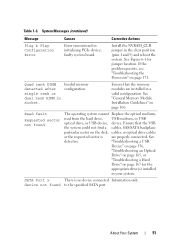
... encountered in socket. See Figure 6-1 for the appropriate drive(s) installed in your system. device not found The operating system cannot Replace the optical medium, read from the hard drive, USB medium, or USB optical drive, or USB device, device. Read fault Requested sector ...the specified SATA port. "Troubleshooting a USB Device" on page 156, "Troubleshooting an Optical Drive" on page 165, or "Troubleshooting a Hard Drive" on the disk, cables, or optical drive cables or the requested sector is no device connected Information only. Quad rank DIMM Invalid memory...
... encountered in socket. See Figure 6-1 for the appropriate drive(s) installed in your system. device not found The operating system cannot Replace the optical medium, read from the hard drive, USB medium, or USB optical drive, or USB device, device. Read fault Requested sector ...the specified SATA port. "Troubleshooting a USB Device" on page 156, "Troubleshooting an Optical Drive" on page 165, or "Troubleshooting a Hard Drive" on the disk, cables, or optical drive cables or the requested sector is no device connected Information only. Quad rank DIMM Invalid memory...
Hardware Owner's Manual
Page 52
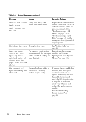
...on page 167 for Memory BIOS. The BIOS setting has Sparing mode. System Messages (continued) Message Causes Corrective Actions Sector not found Faulty hard drive, USB Seek error device, or USB medium. Shutdown failure General system error. Seek operation failed Replace the USB medium or device. See... "Troubleshooting a USB Device" on page 156 or "Troubleshooting a Hard Drive" on page 162. 52 About Your System For sparing mode, matched sets of Memory has been added or system memory has removed or ...
...on page 167 for Memory BIOS. The BIOS setting has Sparing mode. System Messages (continued) Message Causes Corrective Actions Sector not found Faulty hard drive, USB Seek error device, or USB medium. Shutdown failure General system error. Seek operation failed Replace the USB medium or device. See... "Troubleshooting a USB Device" on page 156 or "Troubleshooting a Hard Drive" on page 162. 52 About Your System For sparing mode, matched sets of Memory has been added or system memory has removed or ...


