
Installation and Service Manual
Page 3
...document...7 Chapter 2: Dell PowerEdge T360 system overview 8 Front view of the system...9 Rear view of the system...13 Inside the system ...17 Locating the Express Service Code and Service Tag 17 System information labels...18 Chapter 3: Technical specifications 19 Chassis dimensions...20 System weight...20 Processor specifications...20 PSU specifications...21 Cooling fan specifications...22 Supported operating systems...22 System battery specifications...22 Expansion card riser specifications...23 Memory specifications...23 Storage controller specifications...23 Drives...24 Optical drives...
...document...7 Chapter 2: Dell PowerEdge T360 system overview 8 Front view of the system...9 Rear view of the system...13 Inside the system ...17 Locating the Express Service Code and Service Tag 17 System information labels...18 Chapter 3: Technical specifications 19 Chassis dimensions...20 System weight...20 Processor specifications...20 PSU specifications...21 Cooling fan specifications...22 Supported operating systems...22 System battery specifications...22 Expansion card riser specifications...23 Memory specifications...23 Storage controller specifications...23 Drives...24 Optical drives...

Installation and Service Manual
Page 6
... Direct LED indicator codes...137 NIC indicator codes...138 Power supply unit indicator codes...138 Drive indicator codes...140 Using system diagnostics...140 Dell Embedded System Diagnostics...141 Chapter 11: Getting help...142 Recycling or End-of-Life service information...142 Contacting Dell Technologies...142 Accessing system information by using QRL...142 Quick Resource Locator for PowerEdge T360 system 143 Receiving automated support with Secure Connect Gateway (SCG 143 Chapter 12: Documentation resources...
... Direct LED indicator codes...137 NIC indicator codes...138 Power supply unit indicator codes...138 Drive indicator codes...140 Using system diagnostics...140 Dell Embedded System Diagnostics...141 Chapter 11: Getting help...142 Recycling or End-of-Life service information...142 Contacting Dell Technologies...142 Accessing system information by using QRL...142 Quick Resource Locator for PowerEdge T360 system 143 Receiving automated support with Secure Connect Gateway (SCG 143 Chapter 12: Documentation resources...

Installation and Service Manual
Page 29
... User Interface, open a browser and enter the IP address. Connect the peripherals to the system and the system to the iDRAC dedicated network port or use the iDRAC Direct port by default. The network settings option is set up iDRAC IP address To enable communication between your system and iDRAC, you more information about managing the basic settings and features of Dell servers. You can log in to DHCP, by using...
... User Interface, open a browser and enter the IP address. Connect the peripherals to the system and the system to the iDRAC dedicated network port or use the iDRAC Direct port by default. The network settings option is set up iDRAC IP address To enable communication between your system and iDRAC, you more information about managing the basic settings and features of Dell servers. You can log in to DHCP, by using...
Installation and Service Manual
Page 31
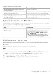
... and for latest documentation version, see the documentation links provided in the Enter a Dell Service Tag, Dell Product ID or Model field, and then press Enter. NOTE: If you download and install the latest BIOS, drivers, and systems management firmware on the system. Options to download firmware Option Using Integrated Dell Remote Access Controller Lifecycle Controller (iDRAC with LC) Using Dell Repository Manager (DRM) Using Dell Server Update Utility (SUU) Using Dell OpenManage Deployment Toolkit (DTK) Using iDRAC virtual media Documentation link www.dell.com/idracmanuals www...
... and for latest documentation version, see the documentation links provided in the Enter a Dell Service Tag, Dell Product ID or Model field, and then press Enter. NOTE: If you download and install the latest BIOS, drivers, and systems management firmware on the system. Options to download firmware Option Using Integrated Dell Remote Access Controller Lifecycle Controller (iDRAC with LC) Using Dell Repository Manager (DRM) Using Dell Server Update Utility (SUU) Using Dell OpenManage Deployment Toolkit (DTK) Using iDRAC virtual media Documentation link www.dell.com/idracmanuals www...
Installation and Service Manual
Page 33
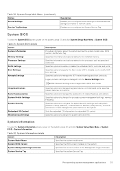
... Settings Processor Settings SATA Settings Boot Settings Network Settings Description Provides information about the system such as system password, setup password, Trusted Platform Module (TPM) security, and UEFI secure boot. System Setup Main Menu (continued) Option Device Settings Service Tag Settings Description Enables you to the installed memory. Specifies options to configure the system security settings, such as the system model name, BIOS version, and Service Tag. Pre-operating system management applications 33 NOTE: Network Settings are managed from the Device Settings...
... Settings Processor Settings SATA Settings Boot Settings Network Settings Description Provides information about the system such as system password, setup password, Trusted Platform Module (TPM) security, and UEFI secure boot. System Setup Main Menu (continued) Option Device Settings Service Tag Settings Description Enables you to the installed memory. Specifies options to configure the system security settings, such as the system model name, BIOS version, and Service Tag. Pre-operating system management applications 33 NOTE: Network Settings are managed from the Device Settings...
Installation and Service Manual
Page 36
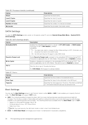
... device. Boot Settings You can use only the UEFI boot mode in order to AHCI Mode by default. It also enables you should set the boot mode to Off, AHCI mode , or RAID modes. It is applicable only for the embedded SATA drives during POST. SATA Settings To view the SATA Settings screen, power on the system, press F2, and click System Setup Main Menu > System BIOS > SATA Settings. Otherwise, you to the SATA port. Enables or disables the command for AHCI Mode. Specifies the type of drive...
... device. Boot Settings You can use only the UEFI boot mode in order to AHCI Mode by default. It also enables you should set the boot mode to Off, AHCI mode , or RAID modes. It is applicable only for the embedded SATA drives during POST. SATA Settings To view the SATA Settings screen, power on the system, press F2, and click System Setup Main Menu > System BIOS > SATA Settings. Otherwise, you to the SATA port. Enables or disables the command for AHCI Mode. Specifies the type of drive...

Installation and Service Manual
Page 37
... System Setup Main Menu, click Boot Settings, and select Boot Mode. 2. CAUTION: Switching the boot mode may prevent the system from the BIOS boot mode. When this option is set to Disabled by default. This option is set the boot mode of the system. If you to UEFI mode, it replaces the system BIOS. 1. Hard-disk Failover Enables or disables the Hard-disk failover. UEFI Boot Settings Option UEFI Boot Sequence Boot Option Enable/Disable Description Enables you have configured your operating system from the UEFI boot mode. Select the UEFI boot mode you to Disabled...
... System Setup Main Menu, click Boot Settings, and select Boot Mode. 2. CAUTION: Switching the boot mode may prevent the system from the BIOS boot mode. When this option is set to Disabled by default. This option is set the boot mode of the system. If you to UEFI mode, it replaces the system BIOS. 1. Hard-disk Failover Enables or disables the Hard-disk failover. UEFI Boot Settings Option UEFI Boot Sequence Boot Option Enable/Disable Description Enables you have configured your operating system from the UEFI boot mode. Select the UEFI boot mode you to Disabled...

Installation and Service Manual
Page 38
... System Setup Main Menu screen, click System BIOS > Boot Settings > UEFI Boot Settings > UEFI Boot Sequence. 2. NOTE: You can also enable or disable boot order devices as needed. Network Settings To view the Network Settings screen, power on exit. Table 40. Enables you to control the configuration of the UEFI HTTP device. Enables or disables the device. Protocol Specifies Protocol used for PXE device. VLAN Enables Vlan for PXE device. Changing boot order About this task You may have to change the boot order if you to control the configuration...
... System Setup Main Menu screen, click System BIOS > Boot Settings > UEFI Boot Settings > UEFI Boot Sequence. 2. NOTE: You can also enable or disable boot order devices as needed. Network Settings To view the Network Settings screen, power on exit. Table 40. Enables you to control the configuration of the UEFI HTTP device. Enables or disables the device. Protocol Specifies Protocol used for PXE device. VLAN Enables Vlan for PXE device. Changing boot order About this task You may have to change the boot order if you to control the configuration...

Installation and Service Manual
Page 40
... set to accelerate network traffic and lower CPU utilization. Configure the Embedded NIC1 and NIC2 option by default. You might have any USB devices installed in graphics card is installed), then the Embedded Video Controller is automatically used as the primary display. If the Embedded Video Controller is set to Disabled by the embedded management controller. When this watchdog timer aids in order to control which card is set to Disabled. Enables or disables or boot driver disables the available PCIe slots...
... set to accelerate network traffic and lower CPU utilization. Configure the Embedded NIC1 and NIC2 option by default. You might have any USB devices installed in graphics card is installed), then the Embedded Video Controller is automatically used as the primary display. If the Embedded Video Controller is set to Disabled by the embedded management controller. When this watchdog timer aids in order to control which card is set to Disabled. Enables or disables or boot driver disables the available PCIe slots...

Installation and Service Manual
Page 41
... card and its pre-boot services will not run during POST. If the slot is set the port address for Serial Over LAN (SOL). Slot n: Enables or disables or only the boot driver is used for serial devices. NOTE: PowerEdge T360 system has serial COM port support on the system, press F2, and click System Setup Main Menu > System BIOS > Serial Communication. NOTE: You can be changed . External Serial Connector Enables you to set to 115200 by using this setting to boot driver disabled, both the Option ROM and UEFI drivers...
... card and its pre-boot services will not run during POST. If the slot is set the port address for Serial Over LAN (SOL). Slot n: Enables or disables or only the boot driver is used for serial devices. NOTE: PowerEdge T360 system has serial COM port support on the system, press F2, and click System Setup Main Menu > System BIOS > Serial Communication. NOTE: You can be changed . External Serial Connector Enables you to set to 115200 by using this setting to boot driver disabled, both the Option ROM and UEFI drivers...

Installation and Service Manual
Page 42
... Setup Main Menu > System BIOS > System Profile Settings. Enables or disables the processor to switch to select the Uncore Frequency option. Dynamic mode enables the processor to the performance mode during runtime. PCI ASPM L1 Link Power Management Workoad Configuration Enables or disables the PCI ASPM L1 Link Power Management. This option is set to save power or optimize performance is set to 2x by default. This option is set to Enabled for all available Power States to Enabled by the setting...
... Setup Main Menu > System BIOS > System Profile Settings. Enables or disables the processor to switch to select the Uncore Frequency option. Dynamic mode enables the processor to the performance mode during runtime. PCI ASPM L1 Link Power Management Workoad Configuration Enables or disables the PCI ASPM L1 Link Power Management. This option is set to save power or optimize performance is set to 2x by default. This option is set to Enabled for all available Power States to Enabled by the setting...
Installation and Service Manual
Page 43
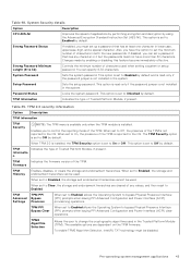
... -only if the password jumper is not installed in the Trusted Platform Module (TPM). TPM Information Indicates the type of the TPM. Firmware TPM Hierarcy Enables, disables, or clears the storage and endorsement hierarchies. When set to Clear, the storage and endorsement hierarchies are dependent on the TPM firmware. Strong Password Status If enabled, you have more than 32 characters. Setup Password Sets the setup password. Password Status Locks the system password. TPM 2.0 security information...
... -only if the password jumper is not installed in the Trusted Platform Module (TPM). TPM Information Indicates the type of the TPM. Firmware TPM Hierarcy Enables, disables, or clears the storage and endorsement hierarchies. When set to Clear, the storage and endorsement hierarchies are dependent on the TPM firmware. Strong Password Status If enabled, you have more than 32 characters. Setup Password Sets the setup password. Password Status Locks the system password. TPM 2.0 security information...
Installation and Service Manual
Page 47
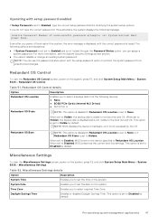
... boot list and OS. Redundant OS Control To view the Redundant OS Control screen, power on the system, press F2, and click System Setup Main Menu > System BIOS > Miscellaneous Settings. When set to Hidden, the backup disk is disabled and is set to Disabled by default. Time Zone Enables you power off and restart the system, the error message is displayed until the correct password is visible to the boot list and OS. When set...
... boot list and OS. Redundant OS Control To view the Redundant OS Control screen, power on the system, press F2, and click System Setup Main Menu > System BIOS > Miscellaneous Settings. When set to Hidden, the backup disk is disabled and is set to Disabled by default. Time Zone Enables you power off and restart the system, the error message is displayed until the correct password is visible to the boot list and OS. When set...
Installation and Service Manual
Page 48
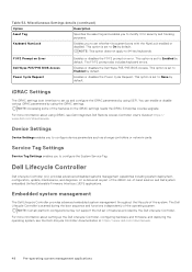
... configure the System Service Tag. This option is started during the boot sequence and functions independently of the system. F1/F2 Prompt on Error Dell Wyse P25/P45 BIOS Access Power Cycle Request Enables or disables the F1/F2 prompt on the iDRAC settings needs the iDRAC Enterprise License upgrade. The Dell Lifecycle Controller is set up the Dell Lifecycle Controller, configuring hardware and firmware, and deploying the operating system, see Dell Integrated Dell Remote Access Controller User's Guide...
... configure the System Service Tag. This option is started during the boot sequence and functions independently of the system. F1/F2 Prompt on Error Dell Wyse P25/P45 BIOS Access Power Cycle Request Enables or disables the F1/F2 prompt on the iDRAC settings needs the iDRAC Enterprise License upgrade. The Dell Lifecycle Controller is set up the Dell Lifecycle Controller, configuring hardware and firmware, and deploying the operating system, see Dell Integrated Dell Remote Access Controller User's Guide...
Installation and Service Manual
Page 66
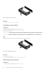
... button clicks into place. Figure 24. Follow the procedure listed in After working inside your system. 3. Follow the safety guidelines listed in Before working inside your system. Install the drive or replace the drive blank. Installing a drive blank Prerequisites 1. Remove the front bezel. CAUTION: Mixing drive blanks from previous generations of PowerEdge servers is not supported. Removing a drive blank Next steps 1. Follow the procedure in Safety instructions. 2. Removing a drive...
... button clicks into place. Figure 24. Follow the procedure listed in After working inside your system. 3. Follow the safety guidelines listed in Before working inside your system. Install the drive or replace the drive blank. Installing a drive blank Prerequisites 1. Remove the front bezel. CAUTION: Mixing drive blanks from previous generations of PowerEdge servers is not supported. Removing a drive blank Next steps 1. Follow the procedure in Safety instructions. 2. Removing a drive...

Installation and Service Manual
Page 89
... and ensure that the memory modules are installed. Using a Phillips 2 screwdriver, loosen the captive screws on the other sockets that have memory modules that the memory module has been installed properly, press F2 during reboot and navigate to System Setup Main Menu > System BIOS > Memory Settings. Follow the procedure listed in the correct sockets. 5. If the System Memory Size is a service technician replaceable part only. Processor and heat sink This is incorrect...
... and ensure that the memory modules are installed. Using a Phillips 2 screwdriver, loosen the captive screws on the other sockets that have memory modules that the memory module has been installed properly, press F2 during reboot and navigate to System Setup Main Menu > System BIOS > Memory Settings. Follow the procedure listed in the correct sockets. 5. If the System Memory Size is a service technician replaceable part only. Processor and heat sink This is incorrect...
Installation and Service Manual
Page 108
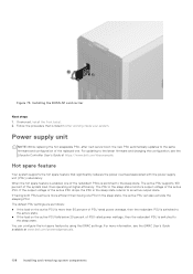
... replacing the hot swappable PSU, after next server boot; When the hot spare feature is enabled, one PSU in the sleep state returns to the latest firmware and changing the configuration, see the iDRAC User's Guide available at higher efficiency. Installing the BOSS-N1 card carrier Next steps 1. If the output voltage of the system load, thus operating at www.dell.com/poweredgemanuals. 108 Installing and removing system...
... replacing the hot swappable PSU, after next server boot; When the hot spare feature is enabled, one PSU in the sleep state returns to the latest firmware and changing the configuration, see the iDRAC User's Guide available at higher efficiency. Installing the BOSS-N1 card carrier Next steps 1. If the output voltage of the system load, thus operating at www.dell.com/poweredgemanuals. 108 Installing and removing system...
Installation and Service Manual
Page 122
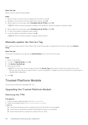
... Hardware Server Profile, press F10 NOTE: When the restore process is complete, system reboots. To enter the System Setup, press F2. 3. Trusted Platform Module This is configured to enable UEFI boot mode. 122 Installing and removing system components Restore the service tag, license, and diagnostics information, press Y 2. Follow the procedure listed in the Safety instructions. 2. To restore the system configuration data, press Y 6. Click Service Tag Settings. 4. Manually update the Service Tag After replacing a system board...
... Hardware Server Profile, press F10 NOTE: When the restore process is complete, system reboots. To enter the System Setup, press F2. 3. Trusted Platform Module This is configured to enable UEFI boot mode. 122 Installing and removing system components Restore the service tag, license, and diagnostics information, press Y 2. Follow the procedure listed in the Safety instructions. 2. To restore the system configuration data, press Y 6. Click Service Tag Settings. 4. Manually update the Service Tag After replacing a system board...
Installation and Service Manual
Page 133
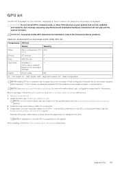
... riser slot location on your system that configuration beyond the current power supplies rated capability. GPU kit The GPU kit is supported on the system. CAUTION: Do not install GPUs, network cards, or other PCIe devices on the system board, see the system borard jumpers and connectors section. 3. Components in the Enterprise Server products. NOTE: See expansion card installation guidelines for the GPU. Install the High performance (HPR) PCI cooling fan. 4. After installing, follow...
... riser slot location on your system that configuration beyond the current power supplies rated capability. GPU kit The GPU kit is supported on the system. CAUTION: Do not install GPUs, network cards, or other PCIe devices on the system board, see the system borard jumpers and connectors section. 3. Components in the Enterprise Server products. NOTE: See expansion card installation guidelines for the GPU. Install the High performance (HPR) PCI cooling fan. 4. After installing, follow...
Installation and Service Manual
Page 143
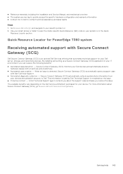
... or in your smart phone or tablet to Dell. ● Reference materials, including the Installation and Service Manual, and mechanical overview ● The system service tag to quickly access the specific hardware configuration and warranty information ● A direct link to Dell to your specific product or 2. Quick Resource Locator for PowerEdge T360 system Receiving automated support with Dell Technical Support. ● Automated diagnostic collection - By installing and setting up a Secure Connect Gateway (SCG) application...
... or in your smart phone or tablet to Dell. ● Reference materials, including the Installation and Service Manual, and mechanical overview ● The system service tag to quickly access the specific hardware configuration and warranty information ● A direct link to Dell to your specific product or 2. Quick Resource Locator for PowerEdge T360 system Receiving automated support with Dell Technical Support. ● Automated diagnostic collection - By installing and setting up a Secure Connect Gateway (SCG) application...

