
Glossary
Page 2
control panel - See processor. DDR - Dual in memory modules that allows the operating system or some specialized function to the system by transferring data on your system. ...
control panel - See processor. DDR - Dual in memory modules that allows the operating system or some specialized function to the system by transferring data on your system. ...

User Manual
Page 3
... to extend the feet poses the risk of the Tower System 3 Stabilizing The Tower System WARNING: The tower system has four feet on its bottom panel that came with your system and identify each item. Unpacking The System Unpack your system. Figure 1. Extending the Feet of having the system tip over...
... to extend the feet poses the risk of the Tower System 3 Stabilizing The Tower System WARNING: The tower system has four feet on its bottom panel that came with your system and identify each item. Unpacking The System Unpack your system. Figure 1. Extending the Feet of having the system tip over...

Owner's Manual
Page 3
......15 Home Screen...16 Setup Menu...16 View Menu...17 Diagnostic Indicators...17 Hard-Drive Indicator Patterns...19 Back-Panel Features And Indicators...20 NIC Indicator Codes...22 Power Indicator Codes For Redundant Power Supply 22 Power Indicator Codes For Non-Redundant Power Supply 23 ...
......15 Home Screen...16 Setup Menu...16 View Menu...17 Diagnostic Indicators...17 Hard-Drive Indicator Patterns...19 Back-Panel Features And Indicators...20 NIC Indicator Codes...22 Power Indicator Codes For Redundant Power Supply 22 Power Indicator Codes For Non-Redundant Power Supply 23 ...

Owner's Manual
Page 6
... System Battery...104 Replacing The System Battery...104 Control-Panel Assembly...105 Removing The Control-Panel Assembly...106 Installing The Control-Panel Assembly...109 Removing The Control Panel...109 Installing The Control Panel...111 Removing The Control-Panel Board For Systems With LCD Modules 111 Installing The Control-Panel Board For Systems With LCD Modules 112 Removing...
... System Battery...104 Replacing The System Battery...104 Control-Panel Assembly...105 Removing The Control-Panel Assembly...106 Installing The Control-Panel Assembly...109 Removing The Control Panel...109 Installing The Control Panel...111 Removing The Control-Panel Board For Systems With LCD Modules 111 Installing The Control-Panel Board For Systems With LCD Modules 112 Removing...

Owner's Manual
Page 9
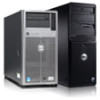
1 About Your System Front-Panel Features And Indicators-Tower Mode Figure 1. Front-Panel Features and Indicators-2.5 Inch Hot-Swappable Hard-Drive Chassis 9
1 About Your System Front-Panel Features And Indicators-Tower Mode Figure 1. Front-Panel Features and Indicators-2.5 Inch Hot-Swappable Hard-Drive Chassis 9

Owner's Manual
Page 10
... 5.25 inch removable media storage device. 2 Optical drive 2 (optional) 3 Optical drive 1 (optional) Up to two optional SATA DVD-ROM drive or DVD+/-RW drive. Front-Panel Features and Indicators-3.5 Inch Hot-Swappable Hard-Drive Chassis Item Indicator, Button, or Icon Description Connector 1 Tape drive (optional) One optional 5.25 inch tape drive...
... 5.25 inch removable media storage device. 2 Optical drive 2 (optional) 3 Optical drive 1 (optional) Up to two optional SATA DVD-ROM drive or DVD+/-RW drive. Front-Panel Features and Indicators-3.5 Inch Hot-Swappable Hard-Drive Chassis Item Indicator, Button, or Icon Description Connector 1 Tape drive (optional) One optional 5.25 inch tape drive...
Owner's Manual
Page 11
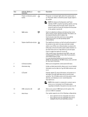
...LCD lights blue during POST, press and hold for more than five seconds to locate a particular system within a rack. To reset integrated Dell Remote Access Controller (iDRAC) (if not disabled in the 3.5 inch hard-drive carriers 11 Use this button only if directed to the... to toggle the system ID on and off . 5 NMI button 6 System identification button 7 LCD menu buttons 8 Information tag 9 LCD panel Used to troubleshoot software and device driver errors when running certain operating systems. This button can be pressed using the power button causes the system...
...LCD lights blue during POST, press and hold for more than five seconds to locate a particular system within a rack. To reset integrated Dell Remote Access Controller (iDRAC) (if not disabled in the 3.5 inch hard-drive carriers 11 Use this button only if directed to the... to toggle the system ID on and off . 5 NMI button 6 System identification button 7 LCD menu buttons 8 Information tag 9 LCD panel Used to troubleshoot software and device driver errors when running certain operating systems. This button can be pressed using the power button causes the system...

Owner's Manual
Page 12
One optional SATA DVD-ROM drive or DVD+/-RW drive. 12 Front-Panel Features and Indicators-3.5 Inch Cabled Hard-Drive Chassis NOTE: Cabled hard-drive systems are not rackable. Item Indicator, Button, or Icon Description Connector • Up to sixteen 2.5 inch hot-swappable hard drives Figure 3. Item Indicator, Button, or Icon Connector 1 Tape drive (optional) 2 Optical drive (optional) Description One optional 5.25 inch tape drive.
One optional SATA DVD-ROM drive or DVD+/-RW drive. 12 Front-Panel Features and Indicators-3.5 Inch Cabled Hard-Drive Chassis NOTE: Cabled hard-drive systems are not rackable. Item Indicator, Button, or Icon Description Connector • Up to sixteen 2.5 inch hot-swappable hard drives Figure 3. Item Indicator, Button, or Icon Connector 1 Tape drive (optional) 2 Optical drive (optional) Description One optional 5.25 inch tape drive.
Owner's Manual
Page 13
... the system can be used to locate a particular system within a rack. A slide-out label panel which allows you to connect USB devices to troubleshoot software and device driver errors when running certain operating systems. This button can be pressed ... . 4 NMI button 5 System identification button 6 Information tag 7 Diagnostic indicators 8 USB connectors (2) Used to the system. When one of these buttons is pressed, the LCD panel on the front chassis and the system status indicator on . If the system stops responding during POST, press and hold for more than five seconds...
... the system can be used to locate a particular system within a rack. A slide-out label panel which allows you to connect USB devices to troubleshoot software and device driver errors when running certain operating systems. This button can be pressed ... . 4 NMI button 5 System identification button 6 Information tag 7 Diagnostic indicators 8 USB connectors (2) Used to the system. When one of these buttons is pressed, the LCD panel on the front chassis and the system status indicator on . If the system stops responding during POST, press and hold for more than five seconds...

Owner's Manual
Page 14
.... Use this button only if directed to the system. When one of these buttons is pressed, the LCD panel on the front and the system status indicator on the front and back panels can be pressed using the power button causes the system to perform a graceful shutdown before power to the system... the system stops responding during POST, press and hold the system ID button for more than five seconds to toggle the system ID on . Front-Panel Features And Indicators-Rack Mode Figure 4. Front-Panel Features and Indicators NOTE: Only systems with hot-swappable hard drives are rackable.
.... Use this button only if directed to the system. When one of these buttons is pressed, the LCD panel on the front and the system status indicator on the front and back panels can be pressed using the power button causes the system to perform a graceful shutdown before power to the system... the system stops responding during POST, press and hold the system ID button for more than five seconds to toggle the system ID on . Front-Panel Features And Indicators-Rack Mode Figure 4. Front-Panel Features and Indicators NOTE: Only systems with hot-swappable hard drives are rackable.
Owner's Manual
Page 15
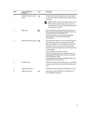
...the system supports only one of whether the system is installed with hot-swappable hard drives. Up to the system. The system's LCD panel provides system information and status and error messages to the system. The LCD lights blue during normal operating conditions and lights amber to record ...device. 11 Tape drive (optional) One 5.25 inch optional tape drive. The LCD lights amber when the system needs attention, and the LCD panel displays an error code followed by descriptive text. See System Error Messages for more than 15 seconds. 4 LCD menu buttons Allow you to ...
...the system supports only one of whether the system is installed with hot-swappable hard drives. Up to the system. The system's LCD panel provides system information and status and error messages to the system. The LCD lights blue during normal operating conditions and lights amber to record ...device. 11 Tape drive (optional) One 5.25 inch optional tape drive. The LCD lights amber when the system needs attention, and the LCD panel displays an error code followed by descriptive text. See System Error Messages for more than 15 seconds. 4 LCD menu buttons Allow you to ...

Owner's Manual
Page 16
... NOTE: When you select an option in the Setup menu, you must confirm the option before proceeding to configure the network mode. LCD Panel Features Item Button Description 1 Left Moves the cursor back in one-step increments. 2 Select Selects the menu item highlighted by pressing either ...the Select, Left, or Right indicator button on the LCD panel. • The LCD backlight remains off if LCD messaging is displayed, and then select the Home icon. Option iDRAC Description Select DHCP ...
... NOTE: When you select an option in the Setup menu, you must confirm the option before proceeding to configure the network mode. LCD Panel Features Item Button Description 1 Left Moves the cursor back in one-step increments. 2 Select Selects the menu item highlighted by pressing either ...the Select, Left, or Right indicator button on the LCD panel. • The LCD backlight remains off if LCD messaging is displayed, and then select the Home icon. Option iDRAC Description Select DHCP ...
Owner's Manual
Page 17
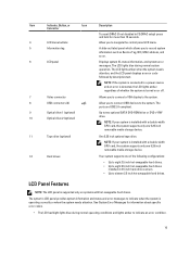
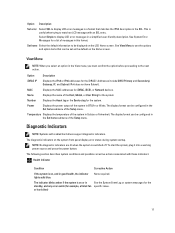
... the system. Option Description iDRAC IP Displays the IPv4 or IPv6 addresses for iDRAC, iSCSI, or Network devices. The diagnostic indicators on the system front panel display error status during system startup. None required. Option Description Set error Select SEL to display LCD error messages in a format that can be set...
... the system. Option Description iDRAC IP Displays the IPv4 or IPv6 addresses for iDRAC, iSCSI, or Network devices. The diagnostic indicators on the system front panel display error status during system startup. None required. Option Description Set error Select SEL to display LCD error messages in a format that can be set...
Owner's Manual
Page 18
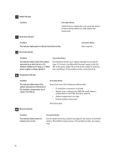
...-filler bracket is removed. • Ambient temperature is too high. • External airflow is removed or has failed. • System cover, cooling shroud, EMI filler panel, memory- Hard-drive Indicator Condition The indicator lights green to a problem with the power supply, check the LED on the power supply. Corrective Action See...
...-filler bracket is removed. • Ambient temperature is too high. • External airflow is removed or has failed. • System cover, cooling shroud, EMI filler panel, memory- Hard-drive Indicator Condition The indicator lights green to a problem with the power supply, check the LED on the power supply. Corrective Action See...

Owner's Manual
Page 20
Non-redundant One 350 W non-redundant AC power power supply supply. 20 Back-Panel Features and Indicators Item Indicator, Button, or Icon Connector 1 Power supplies (PSU1 and PSU2) Description Redundant power supply Up to two 495 W or 750 W AC redundant power supplies. Back-Panel Features And Indicators Figure 7.
Non-redundant One 350 W non-redundant AC power power supply supply. 20 Back-Panel Features and Indicators Item Indicator, Button, or Icon Connector 1 Power supplies (PSU1 and PSU2) Description Redundant power supply Up to two 495 W or 750 W AC redundant power supplies. Back-Panel Features And Indicators Figure 7.

Owner's Manual
Page 21
... Allows you to connect up to five full-height PCIe expansion cards. Slot for routing the power cable of the buttons is pressed, the LCD panel on the front and the system status indicator on the back flash until one of these buttons is pressed again. To reset iDRAC (if not... a VGA display to the system. Two integrated 10/100/1000 Mbps NIC connectors. Allows you to toggle the system ID on the front and back panels can be used to the system. Press to connect the optional system status indicator assembly through the optional cable management arm. If the system stops...
... Allows you to connect up to five full-height PCIe expansion cards. Slot for routing the power cable of the buttons is pressed, the LCD panel on the front and the system status indicator on the back flash until one of these buttons is pressed again. To reset iDRAC (if not... a VGA display to the system. Two integrated 10/100/1000 Mbps NIC connectors. Allows you to toggle the system ID on the front and back panels can be used to the system. Press to connect the optional system status indicator assembly through the optional cable management arm. If the system stops...

Owner's Manual
Page 105
system battery 6. Install the cooling shroud. 11. Control-Panel Assembly The control-panel assembly consists of battery connector 2. To remove the battery, support the battery connector by pressing down firmly on , including any attached peripherals. 14. Lift ...surface. 3. Enter the correct time and date in rack mode only) 105 Locate the battery socket. positive side of the following: • Control-panel board • Control panel with LCD module or diagnostic indicators • VGA module (For systems in the System Setup Time and Date fields. 16. To install a new ...
system battery 6. Install the cooling shroud. 11. Control-Panel Assembly The control-panel assembly consists of battery connector 2. To remove the battery, support the battery connector by pressing down firmly on , including any attached peripherals. 14. Lift ...surface. 3. Enter the correct time and date in rack mode only) 105 Locate the battery socket. positive side of the following: • Control-panel board • Control panel with LCD module or diagnostic indicators • VGA module (For systems in the System Setup Time and Date fields. 16. To install a new ...

Owner's Manual
Page 106
... slip back into the chassis. Removing and Installing the Control-Panel assembly With an LCD Module in your warranty. LCD module ZIF connector 2. screw 106 Read and follow the safety instructions that is not authorized by Dell is not covered by your product documentation, or as it can... damage the connectors. 6. The control-panel assembly with LCD module is supported on systems with cabled hard drives and systems with an...
... slip back into the chassis. Removing and Installing the Control-Panel assembly With an LCD Module in your warranty. LCD module ZIF connector 2. screw 106 Read and follow the safety instructions that is not authorized by Dell is not covered by your product documentation, or as it can... damage the connectors. 6. The control-panel assembly with LCD module is supported on systems with cabled hard drives and systems with an...

Owner's Manual
Page 107
screw 107 control panel board 2. control-panel assembly cable connector 4. 5. control panel Figure 57. Removing and Installing the Control-Panel Assembly With Diagnostic Indicators in a Tower-Mode System 1. control-panel assembly connector 3. control-panel assembly 6.
screw 107 control panel board 2. control-panel assembly cable connector 4. 5. control panel Figure 57. Removing and Installing the Control-Panel Assembly With Diagnostic Indicators in a Tower-Mode System 1. control-panel assembly connector 3. control-panel assembly 6.

Owner's Manual
Page 108
... slot to press the tabs on the information tag. Removing and Installing the Information Tag 1. tabs (2) 108 control-panel assembly connector 5. control-panel board 8. information tag 2. VGA module connector 3. VGA module cable connector 4. screw 7. Figure 59. control panel for replacement in a Rack-Mode System 1. b) Use a flat screwdriver to remove it from the control...
... slot to press the tabs on the information tag. Removing and Installing the Information Tag 1. tabs (2) 108 control-panel assembly connector 5. control-panel board 8. information tag 2. VGA module connector 3. VGA module cable connector 4. screw 7. Figure 59. control panel for replacement in a Rack-Mode System 1. b) Use a flat screwdriver to remove it from the control...


