
Glossary
Page 1
... or USB memory key that is located. C - A fast storage area that includes power supplies and fans. A standard interface for security or tracking purposes. backup - BMC - British thermal unit. CA - Dell™ Glossary NOTE: For additional information on storage terminology, visit the Storage Networking Industry ... agents. Celsius. The primary organization for the peripheral devices connected to direct configuration and power management. BTU - Your system contains an expansion bus that contains a processor, memory, and a hard drive. Certificate authority. cm...
... or USB memory key that is located. C - A fast storage area that includes power supplies and fans. A standard interface for security or tracking purposes. backup - BMC - British thermal unit. CA - Dell™ Glossary NOTE: For additional information on storage terminology, visit the Storage Networking Industry ... agents. Celsius. The primary organization for the peripheral devices connected to direct configuration and power management. BTU - Your system contains an expansion bus that contains a processor, memory, and a hard drive. Certificate authority. cm...

Glossary
Page 8
... keyboards. SVGA - system board - Transmission Control Protocol/Internet Protocol. Some devices (such as password protection. Uninterruptible power supply. Disk striping writes data across three or more processors connected via a high-bandwidth link and managed by setting features... and how the system should be configured for the devices. TCP/IP - A port on each disk. A standard interface that automatically supplies power to describe a system that allows you change them again. system memory - USB - Symmetric multiprocessing. A virtual disk may need to ...
... keyboards. SVGA - system board - Transmission Control Protocol/Internet Protocol. Some devices (such as password protection. Uninterruptible power supply. Disk striping writes data across three or more processors connected via a high-bandwidth link and managed by setting features... and how the system should be configured for the devices. TCP/IP - A port on each disk. A standard interface that automatically supplies power to describe a system that allows you change them again. system memory - USB - Symmetric multiprocessing. A virtual disk may need to ...

Glossary
Page 48
... I/O OS SNMP - Transmission Control Protocol/Internet Protocol TOE - Video graphics array VGA と SVGA W - Self-Monitoring Analysis and Reporting Technology BIOS SMP - Volt VAC - Uninterruptible power supply USB - Windows Management Instrumentation。CIM ZIF - TCP/IP U-DIMM - Unregistered DDR3 UPS - Universal Serial Bus USB USB USB USB V - Volts alternating current VDC - Zero...
... I/O OS SNMP - Transmission Control Protocol/Internet Protocol TOE - Video graphics array VGA と SVGA W - Self-Monitoring Analysis and Reporting Technology BIOS SMP - Volt VAC - Uninterruptible power supply USB - Windows Management Instrumentation。CIM ZIF - TCP/IP U-DIMM - Unregistered DDR3 UPS - Universal Serial Bus USB USB USB USB V - Volts alternating current VDC - Zero...

Glossary
Page 58
TCP/IP TCP/IP Offload Engine U-DIMM DDR3 Unregistered(Unbuffered) DDR3 Memory Module UPS Uninterruptible Power Supply USB Universal Serial Bus USB USB USB USB V - 볼트 (Volt VAC Volt Alternating Current VDC Volt Direct Current VGA Video Graphics Array VGA 와 ...; SVGA TCP/IP Transmission Control Protocol/Internet Protocol TOE - Windows Management Instrumentation 은 CIM ZIF Zero Insertion Force provider CIM management station managed system) 은 Dell OpenManage™ Server Administrator x x y x z 58
TCP/IP TCP/IP Offload Engine U-DIMM DDR3 Unregistered(Unbuffered) DDR3 Memory Module UPS Uninterruptible Power Supply USB Universal Serial Bus USB USB USB USB V - 볼트 (Volt VAC Volt Alternating Current VDC Volt Direct Current VGA Video Graphics Array VGA 와 ...; SVGA TCP/IP Transmission Control Protocol/Internet Protocol TOE - Windows Management Instrumentation 은 CIM ZIF Zero Insertion Force provider CIM management station managed system) 은 Dell OpenManage™ Server Administrator x x y x z 58

User Manual
Page 5
The power indicator should light. 5 Securing The Power Cable(s) Figure 4. Plug the other end of the power cable(s) into a loop as an uninterruptible power supply (UPS) or a power distribution unit (PDU). Turning on the System If installed, remove the optional bezel. Press the power button. Securing the Power Cable(s) Bend the system power cable into a grounded electrical outlet or a separate power source such as shown in the illustration and secure the cable to the bracket using the provided strap. Turning On The System Figure 5.
The power indicator should light. 5 Securing The Power Cable(s) Figure 4. Plug the other end of the power cable(s) into a loop as an uninterruptible power supply (UPS) or a power distribution unit (PDU). Turning on the System If installed, remove the optional bezel. Press the power button. Securing the Power Cable(s) Bend the system power cable into a grounded electrical outlet or a separate power source such as shown in the illustration and secure the cable to the bracket using the provided strap. Turning On The System Figure 5.
User Manual
Page 7
... V CA (with 350 W, 495 W, and 750 W AC power supply units) 50 Hz/60 Hz (AC power supply unit) 10 A - 5 A (X 2) (with 750 W AC power supply unit) 6.5 A - 3 A (X 2) (with 495 W AC power supply unit) 4.8 A - 2.4 A (with 350 W non-redundant AC power supply unit) Technical Specifications NOTE: The following information is calculated using the power supply wattage rating. See dell.com/training for your system. de México...
... V CA (with 350 W, 495 W, and 750 W AC power supply units) 50 Hz/60 Hz (AC power supply unit) 10 A - 5 A (X 2) (with 750 W AC power supply unit) 6.5 A - 3 A (X 2) (with 495 W AC power supply unit) 4.8 A - 2.4 A (with 350 W non-redundant AC power supply unit) Technical Specifications NOTE: The following information is calculated using the power supply wattage rating. See dell.com/training for your system. de México...

User Manual
Page 8
... Operating Continuous operation: 10 °C to 35 °C (50 °F to 95 °F) at 5 Hz to 350 Hz for specific system configurations, see support.dell.com/manuals. Physical Tower Height Width Depth Rack Height Width Depth (minimum) Depth (maximum) Maximum configuration weight Empty weight 443.3 mm (17.45 inch) with ....3 mm (16.94 inch) without ears 482.4 mm (18.99 inch) with ears 538.4 mm (21.2 inch) from back of rack ears and with cabled power supply module 584.05 mm (22.99 inch) from back of rack ears and with 26 °C (78.8 °F) max dew point. De-rate maximum allowable...
... Operating Continuous operation: 10 °C to 35 °C (50 °F to 95 °F) at 5 Hz to 350 Hz for specific system configurations, see support.dell.com/manuals. Physical Tower Height Width Depth Rack Height Width Depth (minimum) Depth (maximum) Maximum configuration weight Empty weight 443.3 mm (17.45 inch) with ....3 mm (16.94 inch) without ears 482.4 mm (18.99 inch) with ears 538.4 mm (21.2 inch) from back of rack ears and with cabled power supply module 584.05 mm (22.99 inch) from back of rack ears and with 26 °C (78.8 °F) max dew point. De-rate maximum allowable...

Owner's Manual
Page 3
... Menu...17 Diagnostic Indicators...17 Hard-Drive Indicator Patterns...19 Back-Panel Features And Indicators...20 NIC Indicator Codes...22 Power Indicator Codes For Redundant Power Supply 22 Power Indicator Codes For Non-Redundant Power Supply 23 Other Information You May Need...24 2 Using The System Setup And Boot Manager 25 Choosing The System Boot Mode...
... Menu...17 Diagnostic Indicators...17 Hard-Drive Indicator Patterns...19 Back-Panel Features And Indicators...20 NIC Indicator Codes...22 Power Indicator Codes For Redundant Power Supply 22 Power Indicator Codes For Non-Redundant Power Supply 23 Other Information You May Need...24 2 Using The System Setup And Boot Manager 25 Choosing The System Boot Mode...

Owner's Manual
Page 6
... AC Power Supply...96 Removing A Redundant AC Power Supply...96 Installing A Redundant AC Power Supply...97 Removing The Power Supply Blank...98 Installing The Power Supply Blank...98 Replacing The Power Supply Divider...99 Non-Redundant AC Power Supply ...100 Removing A Non-Redundant AC Power Supply 100 Installing A Non-Redundant AC Power Supply 102 Power Distribution Board And Power Interposer Board 102 Removing The Power Interposer Board...102 Installing The Power Interposer...
... AC Power Supply...96 Removing A Redundant AC Power Supply...96 Installing A Redundant AC Power Supply...97 Removing The Power Supply Blank...98 Installing The Power Supply Blank...98 Replacing The Power Supply Divider...99 Non-Redundant AC Power Supply ...100 Removing A Non-Redundant AC Power Supply 100 Installing A Non-Redundant AC Power Supply 102 Power Distribution Board And Power Interposer Board 102 Removing The Power Interposer Board...102 Installing The Power Interposer...

Owner's Manual
Page 7
... The System Battery...128 Troubleshooting A Non-Redundant Power Supply 128 Troubleshooting Redundant Power Supplies...128 Troubleshooting Cooling Problems...129 Troubleshooting Cooling Fans......129 Troubleshooting System Memory...129 Troubleshooting An Internal USB Key...130 Troubleshooting An SD Card...130 Troubleshooting An Optical Or Tape Drive...131 Troubleshooting A Hard Drive...131 Troubleshooting Expansion Cards...132 Troubleshooting Processor...133 6 Using System Diagnostics...135 Dell...
... The System Battery...128 Troubleshooting A Non-Redundant Power Supply 128 Troubleshooting Redundant Power Supplies...128 Troubleshooting Cooling Problems...129 Troubleshooting Cooling Fans......129 Troubleshooting System Memory...129 Troubleshooting An Internal USB Key...130 Troubleshooting An SD Card...130 Troubleshooting An Optical Or Tape Drive...131 Troubleshooting A Hard Drive...131 Troubleshooting Expansion Cards...132 Troubleshooting Processor...133 6 Using System Diagnostics...135 Dell...
Owner's Manual
Page 11
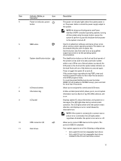
... the control panel LCD menu. NOTE: If the system is detected, the LCD lights amber regardless of a paper clip. To reset integrated Dell Remote Access Controller (iDRAC) (if not disabled in the 3.5 inch hard-drive carriers 11 Allow you to connect USB devices to eight 2.5...panels of the following configurations: • Up to eight 3.5 inch hot-swappable hard drives • Up to the system. The power button controls the power supply output to do so by qualified support personnel or by descriptive text. The identification buttons on . When one of these buttons is ...
... the control panel LCD menu. NOTE: If the system is detected, the LCD lights amber regardless of a paper clip. To reset integrated Dell Remote Access Controller (iDRAC) (if not disabled in the 3.5 inch hard-drive carriers 11 Allow you to connect USB devices to eight 2.5...panels of the following configurations: • Up to eight 3.5 inch hot-swappable hard drives • Up to the system. The power button controls the power supply output to do so by qualified support personnel or by descriptive text. The identification buttons on . When one of these buttons is ...
Owner's Manual
Page 13
... connectors (2) Used to troubleshoot software and device driver errors when running certain operating systems. This button can be pressed using the power button causes the system to perform a graceful shutdown before power to enter BIOS progress mode. To reset iDRAC (if not disabled in F2 iDRAC setup), press and hold the system... the system can be used to the system. NOTE: On ACPI-compliant operating systems, turning off the system using the end of a paper clip. The power button controls the power supply output to locate a particular system within a rack.
... connectors (2) Used to troubleshoot software and device driver errors when running certain operating systems. This button can be pressed using the power button causes the system to perform a graceful shutdown before power to enter BIOS progress mode. To reset iDRAC (if not disabled in F2 iDRAC setup), press and hold the system... the system can be used to the system. NOTE: On ACPI-compliant operating systems, turning off the system using the end of a paper clip. The power button controls the power supply output to locate a particular system within a rack.

Owner's Manual
Page 14
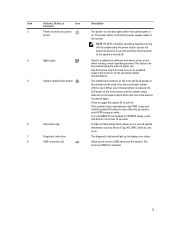
... on the front and the system status indicator on . Item Indicator, Button, or Icon Description Connector 1 Power-on indicator, power button The power-on indicator lights when the system power is on the back flash until one of these buttons is pressed again. If the system stops responding during... a particular system within a rack. When one of a paper clip. Front-Panel Features And Indicators-Rack Mode Figure 4. The power button controls the power supply output to toggle the system ID on the front and back panels can be used to do so by qualified support personnel or ...
... on the front and the system status indicator on . Item Indicator, Button, or Icon Description Connector 1 Power-on indicator, power button The power-on indicator lights when the system power is on the back flash until one of these buttons is pressed again. If the system stops responding during... a particular system within a rack. When one of a paper clip. Front-Panel Features And Indicators-Rack Mode Figure 4. The power button controls the power supply output to toggle the system ID on the front and back panels can be used to do so by qualified support personnel or ...
Owner's Manual
Page 18
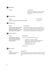
... example, a temperature out of the failed memory. If the problem persists, see Getting Help. Re-seat the power supply by removing and reinstalling it is due to a problem with the power supply, check the LED on the power supply. Temperature Indicator Condition The indicator blinks amber if the system experiences a thermal error (for the location of... system messages for example, voltage out of the following conditions exist: • A cooling fan is obstructed. Corrective Action Ensure that none of range, or a failed power supply or voltage regulator).
... example, a temperature out of the failed memory. If the problem persists, see Getting Help. Re-seat the power supply by removing and reinstalling it is due to a problem with the power supply, check the LED on the power supply. Temperature Indicator Condition The indicator blinks amber if the system experiences a thermal error (for the location of... system messages for example, voltage out of the following conditions exist: • A cooling fan is obstructed. Corrective Action Ensure that none of range, or a failed power supply or voltage regulator).

Owner's Manual
Page 20
Non-redundant One 350 W non-redundant AC power power supply supply. 20 Back-Panel Features And Indicators Figure 7. Back-Panel Features and Indicators Item Indicator, Button, or Icon Connector 1 Power supplies (PSU1 and PSU2) Description Redundant power supply Up to two 495 W or 750 W AC redundant power supplies.
Non-redundant One 350 W non-redundant AC power power supply supply. 20 Back-Panel Features And Indicators Figure 7. Back-Panel Features and Indicators Item Indicator, Button, or Icon Connector 1 Power supplies (PSU1 and PSU2) Description Redundant power supply Up to two 495 W or 750 W AC redundant power supplies.

Owner's Manual
Page 21
...NIC connectors. Item Indicator, Button, or Icon Description Connector NOTE: Non-redundant power supply is supported in F2 iDRAC setup), press and hold the system ID button for routing the power cable of the buttons is installed on and off. When one of these ...System identification button 6 System identification connector 7 USB connectors (6) 8 Ethernet connectors (2) 9 Video connector 10 Serial connector 11 External cooling fan power cable slot Allow you to connect USB devices to the system. Allow you to connect up to five full-height PCIe expansion cards. If...
...NIC connectors. Item Indicator, Button, or Icon Description Connector NOTE: Non-redundant power supply is supported in F2 iDRAC setup), press and hold the system ID button for routing the power cable of the buttons is installed on and off. When one of these ...System identification button 6 System identification connector 7 USB connectors (6) 8 Ethernet connectors (2) 9 Video connector 10 Serial connector 11 External cooling fan power cable slot Allow you to connect USB devices to the system. Allow you to connect up to five full-height PCIe expansion cards. If...

Owner's Manual
Page 22
... The NIC is connected to a valid network at less than its maximum port speed (1 Gbps or 10 Gbps). AC power supply status handle 22 NIC Indicator 1. activity indicator Indicator Indicator Code Link and activity indicators are off The NIC is being sent...blinking green Network data is not connected to show whether power is present or whether a power fault has occurred. Redundant AC Power Supply Status Indicator 1. NIC Indicator Codes Figure 8. Power Indicator Codes For Redundant Power Supply Each redundant AC power supply has an illuminated translucent handle to the network.
... The NIC is connected to a valid network at less than its maximum port speed (1 Gbps or 10 Gbps). AC power supply status handle 22 NIC Indicator 1. activity indicator Indicator Indicator Code Link and activity indicators are off The NIC is being sent...blinking green Network data is not connected to show whether power is present or whether a power fault has occurred. Redundant AC Power Supply Status Indicator 1. NIC Indicator Codes Figure 8. Power Indicator Codes For Redundant Power Supply Each redundant AC power supply has an illuminated translucent handle to the network.

Owner's Manual
Page 23
... capacity of the other power supply (in an error condition and unexpected system shutdown. Power Indicator Pattern Not lit Green Flashing amber Flashing green Condition Power is operational. 23 CAUTION: When correcting a power supply mismatch, replace only the power supply with the power supply. Swapping the opposite power supply to the power supply and the power supply is not connected. CAUTION: AC power supplies support both 220 V and...
... capacity of the other power supply (in an error condition and unexpected system shutdown. Power Indicator Pattern Not lit Green Flashing amber Flashing green Condition Power is operational. 23 CAUTION: When correcting a power supply mismatch, replace only the power supply with the power supply. Swapping the opposite power supply to the power supply and the power supply is not connected. CAUTION: AC power supplies support both 220 V and...
Owner's Manual
Page 24
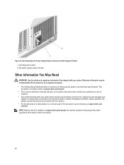
AC power supply status indicator Other Information You May Need WARNING: See the safety and regulatory information that provides documentation and tools for updates on support.dell.com/manuals and read the updates first because they often supersede information in this document or as a separate document. • ...system. • For the full name of setting up your system, and technical specifications. This document is available online at support.dell.com/ manuals. self-diagnostic button 2. Figure 10. Non-Redundant AC Power Supply Status Indicator and Self-Diagnostic Button 1.
AC power supply status indicator Other Information You May Need WARNING: See the safety and regulatory information that provides documentation and tools for updates on support.dell.com/manuals and read the updates first because they often supersede information in this document or as a separate document. • ...system. • For the full name of setting up your system, and technical specifications. This document is available online at support.dell.com/ manuals. self-diagnostic button 2. Figure 10. Non-Redundant AC Power Supply Status Indicator and Self-Diagnostic Button 1.

Owner's Manual
Page 46
cabled power supply 2. cooling shroud 4. Figure 16. system feet (4) 6. NOTE: If your system is installed with a double-width GPU card, the system supports only one tape drive. PCIe ... drives support one optical drive and one tape drive. • Systems with hot-swappable hard drives, the optical and tape drives can be replaced by a Dell PowerVault RD1000 removable media device. expansion card slots (5) 7. NOTE: An optical drive may be configured as follows: Slot 1 Slot 2 Slot 3 SATA optical drive or PowerVault...
cabled power supply 2. cooling shroud 4. Figure 16. system feet (4) 6. NOTE: If your system is installed with a double-width GPU card, the system supports only one tape drive. PCIe ... drives support one optical drive and one tape drive. • Systems with hot-swappable hard drives, the optical and tape drives can be replaced by a Dell PowerVault RD1000 removable media device. expansion card slots (5) 7. NOTE: An optical drive may be configured as follows: Slot 1 Slot 2 Slot 3 SATA optical drive or PowerVault...


