Getting Started Guide
Page 5
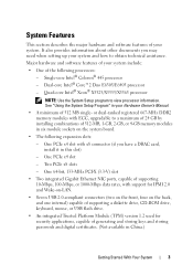
... system and how to obtain technical assistance. Dual-core Intel® Core™2 Duo E6305/E6405 processor - or dual-ranked registered 667-MHz DDR2 memory modules with support for IPMI 2.0 and Wake-on-LAN. • Seven USB 2.0-compliant connectors (two on the front, four on the back, ... software features of your system include: • One of your Hardware Owner's Manual. • A minimum of 512-MB, 1-GB, 2-GB, or 4-GB memory modules in China.) Getting Started With Your System 3 See "Using the System Setup Program" in this slot) - One PCIe x4 slot - It also provides information...
... system and how to obtain technical assistance. Dual-core Intel® Core™2 Duo E6305/E6405 processor - or dual-ranked registered 667-MHz DDR2 memory modules with support for IPMI 2.0 and Wake-on-LAN. • Seven USB 2.0-compliant connectors (two on the front, four on the back, ... software features of your system include: • One of your Hardware Owner's Manual. • A minimum of 512-MB, 1-GB, 2-GB, or 4-GB memory modules in China.) Getting Started With Your System 3 See "Using the System Setup Program" in this slot) - One PCIe x4 slot - It also provides information...
Getting Started Guide
Page 12
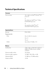
... with x8 connector One x4 Two x8 One 64-bit, 133-MHz, 3.3-V Memory Architecture Memory module sockets Memory module capacities Minimum RAM Maximum RAM 72-bit, single- Technical Specifications Processor Processor type One single-core Intel® Celeron® 445 processor or One ...
... with x8 connector One x4 Two x8 One 64-bit, 133-MHz, 3.3-V Memory Architecture Memory module sockets Memory module capacities Minimum RAM Maximum RAM 72-bit, single- Technical Specifications Processor Processor type One single-core Intel® Celeron® 445 processor or One ...
Getting Started Guide
Page 14
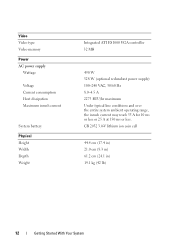
... 44.4 cm (17.4 in) 21.0 cm (8.3 in) 61.2 cm (24.1 in) 19.1 kg (42 lb) 12 Getting Started With Your System Video Video type Video memory Power AC power supply Wattage Voltage Current consumption Heat dissipation Maximum inrush current System battery Physical Height Width Depth Weight Integrated ATI ES1000 VGA controller...
... 44.4 cm (17.4 in) 21.0 cm (8.3 in) 61.2 cm (24.1 in) 19.1 kg (42 lb) 12 Getting Started With Your System Video Video type Video memory Power AC power supply Wattage Voltage Current consumption Heat dissipation Maximum inrush current System battery Physical Height Width Depth Weight Integrated ATI ES1000 VGA controller...

Hardware Owner's Manual (PDF)
Page 4
Responding to Error Messages 41 Using the System Setup Program 42 System Setup Options 43 Main Screen 43 Memory Information Screen 45 CPU Information Screen 46 SATA Configuration Screen 47 Integrated Devices Screen 48 Serial Communication Screen 49 System Security Screen 50 Exit Screen ...
Responding to Error Messages 41 Using the System Setup Program 42 System Setup Options 43 Main Screen 43 Memory Information Screen 45 CPU Information Screen 46 SATA Configuration Screen 47 Integrated Devices Screen 48 Serial Communication Screen 49 System Security Screen 50 Exit Screen ...
Hardware Owner's Manual (PDF)
Page 6
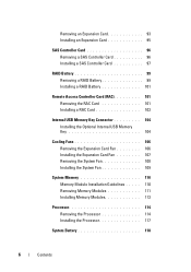
... Access Controller Card (RAC 101 Removing the RAC Card 101 Installing a RAC Card 103 Internal USB Memory Key Connector 104 Installing the Optional Internal USB Memory Key 104 Cooling Fans 106 Removing the Expansion Card Fan 106 Installing the Expansion Card Fan 107 Removing... the System Fan 108 Installing the System Fan 109 System Memory 110 Memory Module Installation Guidelines . . . . . 110 Removing Memory Modules 111 Installing Memory Modules 113 Processor 114 Removing the Processor 114 Installing the Processor 117 System Battery 118 6 ...
... Access Controller Card (RAC 101 Removing the RAC Card 101 Installing a RAC Card 103 Internal USB Memory Key Connector 104 Installing the Optional Internal USB Memory Key 104 Cooling Fans 106 Removing the Expansion Card Fan 106 Installing the Expansion Card Fan 107 Removing... the System Fan 108 Installing the System Fan 109 System Memory 110 Memory Module Installation Guidelines . . . . . 110 Removing Memory Modules 111 Installing Memory Modules 113 Processor 114 Removing the Processor 114 Installing the Processor 117 System Battery 118 6 ...
Hardware Owner's Manual (PDF)
Page 8
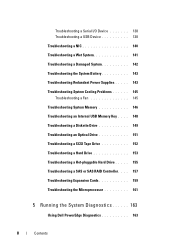
... System Cooling Problems 145 Troubleshooting a Fan 145 Troubleshooting System Memory 146 Troubleshooting an Internal USB Memory Key . . . . 148 Troubleshooting a Diskette Drive... 149 Troubleshooting an Optical Drive 151 Troubleshooting a SCSI Tape Drive 152 Troubleshooting a Hard Drive 153 Troubleshooting a Hot-pluggable Hard Drive . . . . . 155 Troubleshooting a SAS or SAS RAID Controller. . . . 157 Troubleshooting Expansion Cards 159 Troubleshooting the Microprocessor 161 5 Running the System Diagnostics 163 Using Dell PowerEdge...
... System Cooling Problems 145 Troubleshooting a Fan 145 Troubleshooting System Memory 146 Troubleshooting an Internal USB Memory Key . . . . 148 Troubleshooting a Diskette Drive... 149 Troubleshooting an Optical Drive 151 Troubleshooting a SCSI Tape Drive 152 Troubleshooting a Hard Drive 153 Troubleshooting a Hot-pluggable Hard Drive . . . . . 155 Troubleshooting a SAS or SAS RAID Controller. . . . 157 Troubleshooting Expansion Cards 159 Troubleshooting the Microprocessor 161 5 Running the System Diagnostics 163 Using Dell PowerEdge...

Hardware Owner's Manual (PDF)
Page 26
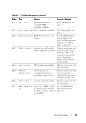
...on page 146. E2016 Int Controller Interrupt controller failure. E201B Kybd Controller Keyboard controller failure. page 146. See "Troubleshooting System Memory" on not functioning properly. See "Getting Help" on page 175. 26 About Your System E2017 Timer Fail Timer refresh ...PDB) is installed in the system. E2010 No Memory No memory is problem persists, replace missing or bad the cable. See "Getting Help" on page 110. Memory System Memory" on during memory page 146. Error detected System Memory" on subsystem failure. E2015 DMA Controller DMA ...
...on page 146. E2016 Int Controller Interrupt controller failure. E201B Kybd Controller Keyboard controller failure. page 146. See "Troubleshooting System Memory" on not functioning properly. See "Getting Help" on page 175. 26 About Your System E2017 Timer Fail Timer refresh ...PDB) is installed in the system. E2010 No Memory No memory is problem persists, replace missing or bad the cable. See "Getting Help" on page 110. Memory System Memory" on during memory page 146. Error detected System Memory" on subsystem failure. E2015 DMA Controller DMA ...
Hardware Owner's Manual (PDF)
Page 27
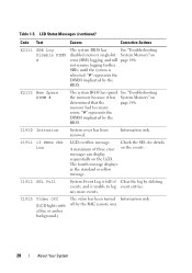
...DIMMs in the See "Troubleshooting set implicated by "# & #" System Memory" on page 146. About Your System 27 E201D Shutdown Test BIOS shutdown test failure. See "Troubleshooting System Memory" on has had a memory multi-bit page 146. Check screen for specific error messages. Check ...error messages. error (MBE). E201E POST Mem Test BIOS POST memory test failure. E2022 POST Fail General failure after video. E2020 CPU Config CPU configuration failure. E2021 Memory Population Incorrect memory configuration. Check screen for specific error messages (see your RAC ...
...DIMMs in the See "Troubleshooting set implicated by "# & #" System Memory" on page 146. About Your System 27 E201D Shutdown Test BIOS shutdown test failure. See "Troubleshooting System Memory" on has had a memory multi-bit page 146. Check screen for specific error messages. Check ...error messages. error (MBE). E201E POST Mem Test BIOS POST memory test failure. E2022 POST Fail General failure after video. E2020 CPU Config CPU configuration failure. E2021 Memory Population Incorrect memory configuration. Check screen for specific error messages (see your RAC ...
Hardware Owner's Manual (PDF)
Page 28
.... 28 About Your System I1910 Intrusion System cover has been removed. E2112 Mem Spare DIMM # The system BIOS has spared See "Troubleshooting the memory because it has System Memory" on the events. messages can display sequentially on error (SBE) logging, and will page 146. I1915 Video Off (LCD lights with a blue ...that the page 146. LCD Status Messages (continued) Code Text Causes Corrective Actions E2111 SBE Log Disable DIMM # The system BIOS has See "Troubleshooting disabled memory single-bit System Memory" on the LCD. off by deleting events, and is rebooted.
.... 28 About Your System I1910 Intrusion System cover has been removed. E2112 Mem Spare DIMM # The system BIOS has spared See "Troubleshooting the memory because it has System Memory" on the events. messages can display sequentially on error (SBE) logging, and will page 146. I1915 Video Off (LCD lights with a blue ...that the page 146. LCD Status Messages (continued) Code Text Causes Corrective Actions E2111 SBE Log Disable DIMM # The system BIOS has See "Troubleshooting disabled memory single-bit System Memory" on the LCD. off by deleting events, and is rebooted.

Hardware Owner's Manual (PDF)
Page 30
... to the same display entry. System Messages System messages appear on the screen to the normal state. If the problem persists, see "Memory Module Installation Guidelines" on page 146. 30 About Your System CAUTION: Only trained service technicians are detected. • A failure is ...an explanation of the components inside the computer, and protecting against electrostatic discharge. Any of these actions will reappear under the following memory DIMMs have been disabled: If more than one DIMM is present. Table 1-3 lists the system messages that maps to remove the...
... to the same display entry. System Messages System messages appear on the screen to the normal state. If the problem persists, see "Memory Module Installation Guidelines" on page 146. 30 About Your System CAUTION: Only trained service technicians are detected. • A failure is ...an explanation of the components inside the computer, and protecting against electrostatic discharge. Any of these actions will reappear under the following memory DIMMs have been disabled: If more than one DIMM is present. Table 1-3 lists the system messages that maps to remove the...
Hardware Owner's Manual (PDF)
Page 31
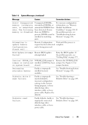
.... attempt failed. Retry the BIOS update. jumper location. Diskette read failure. About Your System 31 Table 1-6. For memory configuration information, see "Memory Module Installation Guidelines" on page 149. Remote Configuration Wait until the process is present, DIMMs must be installed in ...or loose diskette/tape drive interface cable, or loose power cable. Decreasing available memory Faulty or improperly installed memory modules. See "Troubleshooting a Diskette Drive" on page 110. If more memory is disabled: than one DIMM is request has been detected complete. and ...
.... attempt failed. Retry the BIOS update. jumper location. Diskette read failure. About Your System 31 Table 1-6. For memory configuration information, see "Memory Module Installation Guidelines" on page 149. Remote Configuration Wait until the process is present, DIMMs must be installed in ...or loose diskette/tape drive interface cable, or loose power cable. Decreasing available memory Faulty or improperly installed memory modules. See "Troubleshooting a Diskette Drive" on page 110. If more memory is disabled: than one DIMM is request has been detected complete. and ...

Hardware Owner's Manual (PDF)
Page 33
... Faulty or improperly failure at address, read value modules. About Your System 33 expecting value See "Troubleshooting System Memory" on page 175. If connected, defective the problem persists, try keyboard, or defective another keyboard. Table 1-6. System Messages (continued) Message Causes Corrective Actions Keyboard Controller ...
... Faulty or improperly failure at address, read value modules. About Your System 33 expecting value See "Troubleshooting System Memory" on page 175. If connected, defective the problem persists, try keyboard, or defective another keyboard. Table 1-6. System Messages (continued) Message Causes Corrective Actions Keyboard Controller ...
Hardware Owner's Manual (PDF)
Page 34
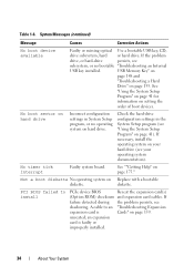
... card is Cards" on page 41). Table 1-6. If the problem drive, or hard-drive persists, see "Using the System Setup Program" on page 159. USB Memory Key" on page 148 and "Troubleshooting a Hard Drive" on setting the order of boot devices.
... card is Cards" on page 41). Table 1-6. If the problem drive, or hard-drive persists, see "Using the System Setup Program" on page 159. USB Memory Key" on page 148 and "Troubleshooting a Hard Drive" on setting the order of boot devices.

Hardware Owner's Manual (PDF)
Page 36
... removed, this message is informative and can be faulty. Time-of system memory has changed Memory has been added or removed or a memory module may be ignored. If the problem persists, replace the system battery (see "Troubleshooting System Memory" on page 118). See "Getting Help" on page 143. The amount... -day clock Faulty battery or faulty stopped chip. See "Troubleshooting the System Battery" on page 175. 36 About Your System If memory has not been added or removed, check the SEL to determine if single-bit or multi-bit errors were detected and replace the faulty...
... removed, this message is informative and can be faulty. Time-of system memory has changed Memory has been added or removed or a memory module may be ignored. If the problem persists, replace the system battery (see "Troubleshooting System Memory" on page 118). See "Getting Help" on page 143. The amount... -day clock Faulty battery or faulty stopped chip. See "Troubleshooting the System Battery" on page 175. 36 About Your System If memory has not been added or removed, check the SEL to determine if single-bit or multi-bit errors were detected and replace the faulty...
Hardware Owner's Manual (PDF)
Page 37
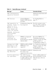
...page 175. DIMM installed in protected mode DIMMs are improperly Reseat the DIMMs. See seated or the "Troubleshooting System keyboard/mouse controller Memory" on Module (TPM) function page 175. The RAID key installed in the RAID DIMM slot! System will now restart. See "Troubleshooting System... Memory" on the boot hard drive. the system is not supported. See the no utility partition exists CDs that came with your on page...
...page 175. DIMM installed in protected mode DIMMs are improperly Reseat the DIMMs. See seated or the "Troubleshooting System keyboard/mouse controller Memory" on Module (TPM) function page 175. The RAID key installed in the RAID DIMM slot! System will now restart. See "Troubleshooting System... Memory" on the boot hard drive. the system is not supported. See the no utility partition exists CDs that came with your on page...

Hardware Owner's Manual (PDF)
Page 39
...task and require you to respond by either the application or the operating system. For more information on valid memory configurations, please see "Troubleshooting System Memory" on selected drive Faulty USB device, USB medium, optical drive assembly, hard drive, or hard-drive subsystem.... Table 1-6. If the problem persists, see the system documentation on support.dell.com Invalid memory Ensure that the memory configuration. Write fault Write fault on page 146. For more information, see the "Glossary" on the hard drive. ...
...task and require you to respond by either the application or the operating system. For more information on valid memory configurations, please see "Troubleshooting System Memory" on selected drive Faulty USB device, USB medium, optical drive assembly, hard drive, or hard-drive subsystem.... Table 1-6. If the problem persists, see the system documentation on support.dell.com Invalid memory Ensure that the memory configuration. Write fault Write fault on page 146. For more information, see the "Glossary" on the hard drive. ...

Hardware Owner's Manual (PDF)
Page 41
... between the installed hardware and configuration settings Entering the System Setup Program 1 Turn on page 30 for an explanation of the message. NOTE: After installing a memory upgrade, it is booting, make a note of the message and suggestions for correcting errors. Using the System Setup Program 41 Record the information for future...
... between the installed hardware and configuration settings Entering the System Setup Program 1 Turn on page 30 for an explanation of the message. NOTE: After installing a memory upgrade, it is booting, make a note of the message and suggestions for correcting errors. Using the System Setup Program 41 Record the information for future...

Hardware Owner's Manual (PDF)
Page 44
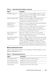
...Type (Auto default) Boot Sequence Retry (Disabled default) Integrated Devices Description Sets the time on page 47). Displays a screen to view memory information and to Enabled, the system re-attempts the boot sequence after a 30-second timeout if the previous boot attempt failed. Available...options can include the diskette drive, CD drive, hard drives, and network. Auto automatically chooses an emulation type. Table 2-2. See support.dell.com for a USB flash drive. Determines the emulation type for the latest support information about booting from an external device attached to ...
...Type (Auto default) Boot Sequence Retry (Disabled default) Integrated Devices Description Sets the time on page 47). Displays a screen to view memory information and to Enabled, the system re-attempts the boot sequence after a 30-second timeout if the previous boot attempt failed. Available...options can include the diskette drive, CD drive, hard drives, and network. Auto automatically chooses an emulation type. Table 2-2. See support.dell.com for a USB flash drive. Determines the emulation type for the latest support information about booting from an external device attached to ...
Hardware Owner's Manual (PDF)
Page 45
...default) Enables or disables reporting of system memory. Memory Information Screen Option System Memory Size System Memory Type System Memory Speed Video Memory Description Displays the amount of keyboard errors during POST. Displays the type of video memory. For further information, see Table 2-8). ... Not Report to suppress all error messages relating to the system. Using the System Setup Program 45 Displays the system memory speed. System Security Displays a screen to configure serial communication, external serial connector, fail-safe baud rate, remote terminal...
...default) Enables or disables reporting of system memory. Memory Information Screen Option System Memory Size System Memory Type System Memory Speed Video Memory Description Displays the amount of keyboard errors during POST. Displays the type of video memory. For further information, see Table 2-8). ... Not Report to suppress all error messages relating to the system. Using the System Setup Program 45 Displays the system memory speed. System Security Displays a screen to configure serial communication, external serial connector, fail-safe baud rate, remote terminal...

Hardware Owner's Manual (PDF)
Page 46
...Option Description 64-bit Specifies if the installed processor supports 64-bit extensions. Core Speed Displays the clock speed of sequential memory access. This feature can only be (Disabled default) running virtualization software. Disable this feature if your system will not.... 46 Using the System Setup Program Bus Speed Displays the bus speed of random memory access. Memory Information Screen (continued) Option System Memory Testing Description Specifies whether system memory tests are Enabled and Disabled. CPU Information Screen Table 2-4 lists the options and ...
...Option Description 64-bit Specifies if the installed processor supports 64-bit extensions. Core Speed Displays the clock speed of sequential memory access. This feature can only be (Disabled default) running virtualization software. Disable this feature if your system will not.... 46 Using the System Setup Program Bus Speed Displays the bus speed of random memory access. Memory Information Screen (continued) Option System Memory Testing Description Specifies whether system memory tests are Enabled and Disabled. CPU Information Screen Table 2-4 lists the options and ...


