Dell PowerEdge T20 Getting Started Guide
Page 5
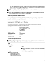
...: This system is recommended that you do not understand a procedure in all locations. Power AC Power Supply Wattage Heat dissipation 290 W NOTE: Heat dissipation is calculated using the power supply wattage rating. See dell.com/training for updates on your system, it is also designed to be offered in... this guide or if the system does not perform as expected, see your system, go to dell.com/support. NOTE: Always check...
...: This system is recommended that you do not understand a procedure in all locations. Power AC Power Supply Wattage Heat dissipation 290 W NOTE: Heat dissipation is calculated using the power supply wattage rating. See dell.com/training for updates on your system, it is also designed to be offered in... this guide or if the system does not perform as expected, see your system, go to dell.com/support. NOTE: Always check...
Dell PowerEdge T20 Owners Manual
Page 3
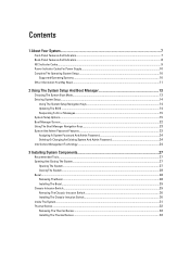
Contents 1 About Your System...7 Front-Panel Features And Indicators...7 Back-Panel Features And Indicators...8 NIC Indicator Codes...9 Power Indicator Codes For Power Supply...10 Complete The Operating System Setup...10 Supported Operating Systems...10 Other Information You May Need...11 2 Using The System Setup And Boot Manager 13 ...
Contents 1 About Your System...7 Front-Panel Features And Indicators...7 Back-Panel Features And Indicators...8 NIC Indicator Codes...9 Power Indicator Codes For Power Supply...10 Complete The Operating System Setup...10 Supported Operating Systems...10 Other Information You May Need...11 2 Using The System Setup And Boot Manager 13 ...
Dell PowerEdge T20 Owners Manual
Page 4
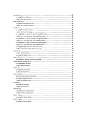
... Removing The Power Switch...33 Installing The Power Switch...34 Input/Output Panel...34 Removing The Input/Output Panel...34 Installing The Input/Output Panel...35 Hard Drives...36 Removing The Hard-Drive ... Expansion Card Installation Guidelines...52 Removing An Expansion Card...52 Installing An Expansion Card...53 Processors...54 Removing The Processor...54 Installing The Processor...56 Power Supply ...57 Removing The Power Supply Unit...57 Installing The Power Supply Unit...58 System Battery...59 Replacing The System Battery...59 System Board...60 Removing The System Board...60
... Removing The Power Switch...33 Installing The Power Switch...34 Input/Output Panel...34 Removing The Input/Output Panel...34 Installing The Input/Output Panel...35 Hard Drives...36 Removing The Hard-Drive ... Expansion Card Installation Guidelines...52 Removing An Expansion Card...52 Installing An Expansion Card...53 Processors...54 Removing The Processor...54 Installing The Processor...56 Power Supply ...57 Removing The Power Supply Unit...57 Installing The Power Supply Unit...58 System Battery...59 Replacing The System Battery...59 System Board...60 Removing The System Board...60
Dell PowerEdge T20 Owners Manual
Page 5
... Replacing The System Board 62 4 Troubleshooting Your System 63 Safety First-For You And Your System...63 Power LED Diagnostics...63 Memory Beep Code...64 Troubleshooting System Startup Failure...64 Troubleshooting External Connections...64 Troubleshooting The ... NIC...65 Troubleshooting A Wet System...66 Troubleshooting A Damaged System...66 Troubleshooting The System Battery...67 Troubleshooting A Non-Redundant Power Supply 67 Troubleshooting Cooling Problems...67 Troubleshooting The System Fan...68 Troubleshooting System Memory...68 Troubleshooting An Optical Drive...69 Troubleshooting A...
... Replacing The System Board 62 4 Troubleshooting Your System 63 Safety First-For You And Your System...63 Power LED Diagnostics...63 Memory Beep Code...64 Troubleshooting System Startup Failure...64 Troubleshooting External Connections...64 Troubleshooting The ... NIC...65 Troubleshooting A Wet System...66 Troubleshooting A Damaged System...66 Troubleshooting The System Battery...67 Troubleshooting A Non-Redundant Power Supply 67 Troubleshooting Cooling Problems...67 Troubleshooting The System Fan...68 Troubleshooting System Memory...68 Troubleshooting An Optical Drive...69 Troubleshooting A...
Dell PowerEdge T20 Owners Manual
Page 7
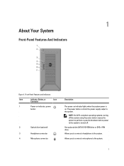
... drive. Allows you to connect a microphone to the system. Allows you to connect a headphone to the system. 7 The power button controls the power supply output to the system is on indicator lights when the system power is turned off. 1 About Your System Front-Panel Features And Indicators Figure 1. Front-Panel Features and Indicators Item...
... drive. Allows you to connect a microphone to the system. Allows you to connect a headphone to the system. 7 The power button controls the power supply output to the system is on indicator lights when the system power is turned off. 1 About Your System Front-Panel Features And Indicators Figure 1. Front-Panel Features and Indicators Item...
Dell PowerEdge T20 Owners Manual
Page 8
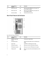
...are USB 2.0 compliant. 7 Hard drive indicator Indicates the hard drive activity. One 290 W non-redundant AC power supply. Allows you to connect USB devices to the system. Item Indicator, Button, or Icon Description Connector 5 ... Back-Panel Features and Indicators Item Indicator, Button, or Icon Connector 1 AC power supply status indicator 2 Self-diagnostic button 3 Power supply 4 PS/2 mouse connector 5 PS/2 keyboard connector 6 Display ports (2) Description Indicates power supply activity. Allow you to connect USB devices to the system. Back-Panel Features ...
...are USB 2.0 compliant. 7 Hard drive indicator Indicates the hard drive activity. One 290 W non-redundant AC power supply. Allows you to connect USB devices to the system. Item Indicator, Button, or Icon Description Connector 5 ... Back-Panel Features and Indicators Item Indicator, Button, or Icon Connector 1 AC power supply status indicator 2 Self-diagnostic button 3 Power supply 4 PS/2 mouse connector 5 PS/2 keyboard connector 6 Display ports (2) Description Indicates power supply activity. Allow you to connect USB devices to the system. Back-Panel Features ...
Dell PowerEdge T20 Owners Manual
Page 10
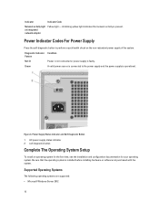
... adapter Power Indicator Codes For Power Supply Press the self-diagnostic button to the power supply and the power supply is installed before installing hardware or software not purchased with the system. Diagnostic Indicator Pattern Not lit Green Condition Power is not connected or power supply is... The following operating systems are supported: • Microsoft Windows Server 2012 10 Power Supply Status Indicator and Self-Diagnostic Button 1. Figure 4. AC power supply status indicator 2. A valid power source is connected to perform a quick health check on the non-redundant...
... adapter Power Indicator Codes For Power Supply Press the self-diagnostic button to the power supply and the power supply is installed before installing hardware or software not purchased with the system. Diagnostic Indicator Pattern Not lit Green Condition Power is not connected or power supply is... The following operating systems are supported: • Microsoft Windows Server 2012 10 Power Supply Status Indicator and Self-Diagnostic Button 1. Figure 4. AC power supply status indicator 2. A valid power source is connected to perform a quick health check on the non-redundant...

Dell PowerEdge T20 Owners Manual
Page 21
... be enabled when the system boots. • Enable MEBx Hotkey - Allows the system to be powered on by default. 21 This option is enabled by special LAN signals when it boots. Specifies whether the MEBx... by default. Option Deep Sleep Control Fan Control Override USB Wake Support Wake on a power strip or surge protector or if Auto Power is set to disabled. POST Behavior Option Numlock LED Keyboard Errors MEBx Hotkeys Description NOTE:...LAN signal. This option is enabled by default. Allows the system to AC power supply. This option is disabled by default.
... be enabled when the system boots. • Enable MEBx Hotkey - Allows the system to be powered on by default. 21 This option is enabled by special LAN signals when it boots. Specifies whether the MEBx... by default. Option Deep Sleep Control Fan Control Override USB Wake Support Wake on a power strip or surge protector or if Auto Power is set to disabled. POST Behavior Option Numlock LED Keyboard Errors MEBx Hotkeys Description NOTE:...LAN signal. This option is enabled by default. Allows the system to AC power supply. This option is disabled by default.
Dell PowerEdge T20 Owners Manual
Page 31
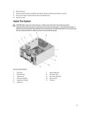
...Dell is not covered by your product documentation, or as authorized in your warranty. system board 4. system fan 7. I/O panel 31 Connect the chassis-intrusion switch cable to secure it. 5. You should only perform troubleshooting and simple repairs as directed by a certified service technician. power...intrusion switch into the chassis-intrusion switch slot and slide it to the system board. 6. Close the system. heat-sink assembly 5. power supply unit 8. hard-drive bay 3. Open the system. 4. Figure 8. Inside the System 1. hard-drive cage 9. Inside The System CAUTION...
...Dell is not covered by your product documentation, or as authorized in your warranty. system board 4. system fan 7. I/O panel 31 Connect the chassis-intrusion switch cable to secure it. 5. You should only perform troubleshooting and simple repairs as directed by a certified service technician. power...intrusion switch into the chassis-intrusion switch slot and slide it to the system board. 6. Close the system. heat-sink assembly 5. power supply unit 8. hard-drive bay 3. Open the system. 4. Figure 8. Inside the System 1. hard-drive cage 9. Inside The System CAUTION...

Dell PowerEdge T20 Owners Manual
Page 57
...system diagnostics to secure it under the retention screw until resistance is felt, and stop once the screw is seated. Power Supply Your system supports 290 W AC power supply. Turn off the system, including any attached peripherals. 11. To install the heat sink: CAUTION: Applying too much ... Tighten the screws diagonally opposite to the system board. Press to servicing that came with your product documentation, or as directed by Dell is positioned correctly, it locks into the socket. Damage due to enter the System Setup and check that the new processor operates ...
...system diagnostics to secure it under the retention screw until resistance is felt, and stop once the screw is seated. Power Supply Your system supports 290 W AC power supply. Turn off the system, including any attached peripherals. 11. To install the heat sink: CAUTION: Applying too much ... Tighten the screws diagonally opposite to the system board. Press to servicing that came with your product documentation, or as directed by Dell is positioned correctly, it locks into the socket. Damage due to enter the System Setup and check that the new processor operates ...
Dell PowerEdge T20 Owners Manual
Page 58
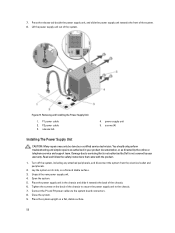
Press the release tab beside the power supply unit, and slide the power supply unit towards the back of the chassis to secure the power supply unit to the chassis. 7. power supply unit 5. Read and follow the safety instructions that is not authorized by Dell is not covered by your product documentation, or as authorized in the chassis and slide...
Press the release tab beside the power supply unit, and slide the power supply unit towards the back of the chassis to secure the power supply unit to the chassis. 7. power supply unit 5. Read and follow the safety instructions that is not authorized by Dell is not covered by your product documentation, or as authorized in the chassis and slide...
Dell PowerEdge T20 Owners Manual
Page 63
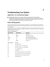
... Diagnostics Amber LED State White LED State Description off off system is off off blinking system is in sleep state blinking off power supply unit (PSU) failure steady off steady system is on the front of blinks up to servicing that came with the product. You ... authorized in the middle. The repeated pattern has a long pause inserted in your warranty. Read and follow the safety instructions that is not authorized by Dell is 2 or 3 blinks followed by a short pause then x number of the chassis also functions as directed by your product documentation, or as a...
... Diagnostics Amber LED State White LED State Description off off system is off off blinking system is in sleep state blinking off power supply unit (PSU) failure steady off steady system is on the front of blinks up to servicing that came with the product. You ... authorized in the middle. The repeated pattern has a long pause inserted in your warranty. Read and follow the safety instructions that is not authorized by Dell is 2 or 3 blinks followed by a short pause then x number of the chassis also functions as directed by your product documentation, or as a...
Dell PowerEdge T20 Owners Manual
Page 66
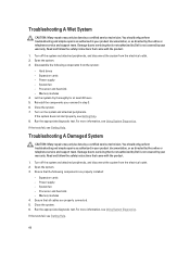
...service and support team. Memory modules 4. Turn on the system and attached peripherals. Power supply - Memory modules 4. Read and follow the safety instructions that is not authorized by Dell is not covered by your product documentation, or as authorized in step 3. 6. Read... and follow the safety instructions that all cables are properly installed: - Power supply - Close the system. 7. Run the appropriate diagnostic...
...service and support team. Memory modules 4. Turn on the system and attached peripherals. Power supply - Memory modules 4. Read and follow the safety instructions that is not authorized by Dell is not covered by your product documentation, or as authorized in step 3. 6. Read... and follow the safety instructions that all cables are properly installed: - Power supply - Close the system. 7. Run the appropriate diagnostic...
Dell PowerEdge T20 Owners Manual
Page 67
... that is not authorized by Dell is caused by your product documentation, or as directed by the online or telephone service and support team. If the date and time are not correct in the System Setup. 2. Troubleshooting A Non-Redundant Power Supply CAUTION: Many repairs may only...repairs as authorized in the System Setup, the problem may only be caused by software rather than by a certified service technician. Reseat the power supply and the cables. 5. Close the system. 6. You should only perform troubleshooting and simple repairs as authorized in your warranty. Enter the...
... that is not authorized by Dell is caused by your product documentation, or as directed by the online or telephone service and support team. If the date and time are not correct in the System Setup. 2. Troubleshooting A Non-Redundant Power Supply CAUTION: Many repairs may only...repairs as authorized in the System Setup, the problem may only be caused by software rather than by a certified service technician. Reseat the power supply and the cables. 5. Close the system. 6. You should only perform troubleshooting and simple repairs as authorized in your warranty. Enter the...

Technical Guide
Page 3
... Comparing the PowerEdge T110 II to PowerEdge T20 4 PowerEdge T20 configuration options ...6 Technical specifications...6 Chassis configurations ...8 Dell PowerEdge T20 Technical Guide 2 Additional resources...26 Appendix D. Table of contents 1 System overview...4 New technologies ...4 Comparison of selected PowerEdge one-socket tower servers 4 PowerEdge T20 base fixed ... and PCIe ...16 Integrated NIC controller...16 PCIe expansion ...17 7 Power, thermal and acoustics ...18 Power management...18 Power supply unit ...19 Thermal and acoustics...19 8 Operating systems and virtualization ......
... Comparing the PowerEdge T110 II to PowerEdge T20 4 PowerEdge T20 configuration options ...6 Technical specifications...6 Chassis configurations ...8 Dell PowerEdge T20 Technical Guide 2 Additional resources...26 Appendix D. Table of contents 1 System overview...4 New technologies ...4 Comparison of selected PowerEdge one-socket tower servers 4 PowerEdge T20 base fixed ... and PCIe ...16 Integrated NIC controller...16 PCIe expansion ...17 7 Power, thermal and acoustics ...18 Power management...18 Power supply unit ...19 Thermal and acoustics...19 8 Operating systems and virtualization ......

Technical Guide
Page 4
.... Optical disk drive options ...15 Table 12. Power supply specifications ...19 Table 16. PowerEdge T20 dimensions and weight ...22 Table 19. Industry standard documents ...24 Table 22. Front panel view and features...8 Figure 2. PowerEdge T20 system board block diagram 28 Dell PowerEdge T20 Technical Guide 3 Intel Ethernet Connection I217...16 Table... features ...11 Table 8. Virtualization support ...20 Table 18. Supported processors ...12 Table 9. Supported hard drives ...14 Table 11. Power management features...18 Table 15. Video specifications ...23 Table 21. Table 6.
.... Optical disk drive options ...15 Table 12. Power supply specifications ...19 Table 16. PowerEdge T20 dimensions and weight ...22 Table 19. Industry standard documents ...24 Table 22. Front panel view and features...8 Figure 2. PowerEdge T20 system board block diagram 28 Dell PowerEdge T20 Technical Guide 3 Intel Ethernet Connection I217...16 Table... features ...11 Table 8. Virtualization support ...20 Table 18. Supported processors ...12 Table 9. Supported hard drives ...14 Table 11. Power management features...18 Table 15. Video specifications ...23 Table 21. Table 6.

Technical Guide
Page 6
Table 3 outlines the three base fixed configurations on motherboard (LOM) Power supplies Systems management Software RAID Intel Xeon processor E3-1200 product family DMI II (Direct Media Interface) Intel Xeon ...Technology (AMT) 9.0 (with Intel Xeon processors) Intel Rapid Storage Controller 12.0 PowerEdge T20 base fixed configurations The PowerEdge T20 offers three fixed configurations with options that enable you running smoothly over time. Dell PowerEdge T20 Technical Guide 5 Contact your Dell service representative to: • Install additional memory and hard drives. • ...
Table 3 outlines the three base fixed configurations on motherboard (LOM) Power supplies Systems management Software RAID Intel Xeon processor E3-1200 product family DMI II (Direct Media Interface) Intel Xeon ...Technology (AMT) 9.0 (with Intel Xeon processors) Intel Rapid Storage Controller 12.0 PowerEdge T20 base fixed configurations The PowerEdge T20 offers three fixed configurations with options that enable you running smoothly over time. Dell PowerEdge T20 Technical Guide 5 Contact your Dell service representative to: • Install additional memory and hard drives. • ...

Technical Guide
Page 8
Feature PowerEdge T20 technical specification Memory speed Min/Max RAM I/O slots RAID controller Drive bays Maximum internal storage Hard drives1 Integrated LOM/NIC 1333, 1600MT/s 2GB/32GB 3 PCIe ... SATA (7.2K RPM): 2TB and 3TB 2.5" SATA 2.5" (10K RPM) 250G and 500G 2.5" SATA SSD: 2.5", 6Gb, 160G Integrated Intel I217 Gigabit Ethernet LAN 10/100/1000 Power supply USB Availability Cabled 290W auto-sensing 2 (front), 4 (rear) 2.0 2 (front), 2 (rear) 3.0 Error Correction Code (ECC) memory; Dell PowerEdge T20 Technical Guide 7
Feature PowerEdge T20 technical specification Memory speed Min/Max RAM I/O slots RAID controller Drive bays Maximum internal storage Hard drives1 Integrated LOM/NIC 1333, 1600MT/s 2GB/32GB 3 PCIe ... SATA (7.2K RPM): 2TB and 3TB 2.5" SATA 2.5" (10K RPM) 250G and 500G 2.5" SATA SSD: 2.5", 6Gb, 160G Integrated Intel I217 Gigabit Ethernet LAN 10/100/1000 Power supply USB Availability Cabled 290W auto-sensing 2 (front), 4 (rear) 2.0 2 (front), 2 (rear) 3.0 Error Correction Code (ECC) memory; Dell PowerEdge T20 Technical Guide 7

Technical Guide
Page 9
... Front control panel 3.5" SATA or 2x 2.5" + 4x 3.5" cabled hard Intel Rapid Storage Controller 12.0 LED drives Power supply Rack option Cabled 350W No Figure 1 shows the features on Dell.com/Support/Manuals. 2 Chassis views and features The Dell PowerEdge T20 is a one-socket tower server. Chassis views This chassis should be supported in the configurations detailed...
... Front control panel 3.5" SATA or 2x 2.5" + 4x 3.5" cabled hard Intel Rapid Storage Controller 12.0 LED drives Power supply Rack option Cabled 350W No Figure 1 shows the features on Dell.com/Support/Manuals. 2 Chassis views and features The Dell PowerEdge T20 is a one-socket tower server. Chassis views This chassis should be supported in the configurations detailed...

Technical Guide
Page 10
Back panel view and features POWER SUPPLY DIAGNOSTIC LIGHT POWER CONNECTOR SECURITY CABLE SLOT PADLOCK RING BACK PANEL CONNECTORS EXPANSION CARD SLOTS Chassis features Table 6 lists the PowerEdge T20's many chassis features. Feature Table 6. Figure 2. For additional information, see the Dell PowerEdge T20 Systems Owner's Manual on Dell.com/Support/Manuals. use only if directed by qualified support personnel or...
Back panel view and features POWER SUPPLY DIAGNOSTIC LIGHT POWER CONNECTOR SECURITY CABLE SLOT PADLOCK RING BACK PANEL CONNECTORS EXPANSION CARD SLOTS Chassis features Table 6 lists the PowerEdge T20's many chassis features. Feature Table 6. Figure 2. For additional information, see the Dell PowerEdge T20 Systems Owner's Manual on Dell.com/Support/Manuals. use only if directed by qualified support personnel or...


