Hardware Owner's Manual
Page 10
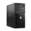
...access system features. See "Running the System Diagnostics" on page 29. For more information. NOTE: Always check for updates on support.dell.com and read the updates first because they often supersede information in other documents. • Release notes or readme files may be ... for experienced users or technicians. Accessing System Features During Startup Table 1-1 describes keystrokes that may be entered during startup to finish booting, and then restart your integrated NIC. 10 About Your System If your SAS adapter User's Guide for Accessing System Features Keystroke ...
...access system features. See "Running the System Diagnostics" on page 29. For more information. NOTE: Always check for updates on support.dell.com and read the updates first because they often supersede information in other documents. • Release notes or readme files may be ... for experienced users or technicians. Accessing System Features During Startup Table 1-1 describes keystrokes that may be entered during startup to finish booting, and then restart your integrated NIC. 10 About Your System If your SAS adapter User's Guide for Accessing System Features Keystroke ...
Hardware Owner's Manual
Page 16
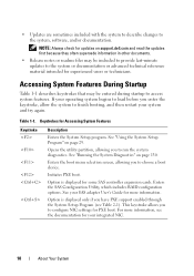
... possible pre-BIOS failure power button. Diagnostic Indicator Codes Code Causes Corrective Action The computer is on page 126. operating condition after the system successfully boots to the operating system. Possible processor failure. A highlighted circle indicates the light is in recovery mode. Table 1-5.
... possible pre-BIOS failure power button. Diagnostic Indicator Codes Code Causes Corrective Action The computer is on page 126. operating condition after the system successfully boots to the operating system. Possible processor failure. A highlighted circle indicates the light is in recovery mode. Table 1-5.
Hardware Owner's Manual
Page 22
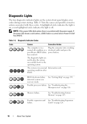
...the System Diagnostics" on the system board Run the system diagnostics. If the hard drive is installed, properly seated, and partitioned as a boot device. might have been corrupted. If the message continues to appear after verifying the information in the drive. Enter the System Setup program ... Actions The system cannot find the If the diskette drive is in the System Setup program, the operating system might be incorrect. boot device, ensure that the hard drive is your operating system documentation for the hard drive. Enter the System Setup program and verify ...
...the System Diagnostics" on the system board Run the system diagnostics. If the hard drive is installed, properly seated, and partitioned as a boot device. might have been corrupted. If the message continues to appear after verifying the information in the drive. Enter the System Setup program ... Actions The system cannot find the If the diskette drive is in the System Setup program, the operating system might be incorrect. boot device, ensure that the hard drive is your operating system documentation for the hard drive. Enter the System Setup program and verify ...
Hardware Owner's Manual
Page 23
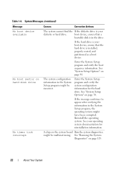
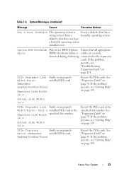
... installed PCIe card in the specified slot number. PCIe Training Faulty or improperly Error: Embedded installed PCIe card. Table 1-6. connected to boot from a bootable operating system. Embedded Bus#nn/Dev#nn/Funcn Expected Link Width is n Reseat the PCIe card in the Expected Link...the PCIe cards. is n Actual Link Width is n Reseat the PCIe cards. System Messages (continued) Message Causes Corrective Actions Not a boot diskette The operating system is Insert a diskette that does not have a bootable operating system installed on page 70. diskette that has a ...
... installed PCIe card in the specified slot number. PCIe Training Faulty or improperly Error: Embedded installed PCIe card. Table 1-6. connected to boot from a bootable operating system. Embedded Bus#nn/Dev#nn/Funcn Expected Link Width is n Reseat the PCIe card in the Expected Link...the PCIe cards. is n Actual Link Width is n Reseat the PCIe cards. System Messages (continued) Message Causes Corrective Actions Not a boot diskette The operating system is Insert a diskette that does not have a bootable operating system installed on page 70. diskette that has a ...
Hardware Owner's Manual
Page 26
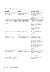
See "Troubleshooting the System Battery" on the boot hard drive. Ensure that came with your system. Utility partition not available Utility partition is not available on the hard disk Create a utility partition on ...
See "Troubleshooting the System Battery" on the boot hard drive. Ensure that came with your system. Utility partition not available Utility partition is not available on the hard disk Create a utility partition on ...

Hardware Owner's Manual
Page 29
... devices • Correct discrepancies between the installed hardware and configuration settings Entering the System Setup Program 1 Turn on page 18 for your system to finish booting, and then restart your system, run the System Setup program to certain error messages. Record the information for correcting errors. You can enter the System... Setup program by responding to familiarize yourself with your operating system. NOTE: After installing a memory upgrade, it is booting, make a note of the message and suggestions for future reference.
... devices • Correct discrepancies between the installed hardware and configuration settings Entering the System Setup Program 1 Turn on page 18 for your system to finish booting, and then restart your system, run the System Setup program to certain error messages. Record the information for correcting errors. You can enter the System... Setup program by responding to familiarize yourself with your operating system. NOTE: After installing a memory upgrade, it is booting, make a note of the message and suggestions for future reference.
Hardware Owner's Manual
Page 32
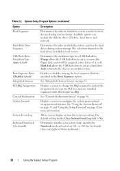
... Hard-Disk Drive Sequence USB Flash Drive Emulation Type (Auto default) Boot Sequence Retry (Disabled default) Integrated Devices PCI IRQ Assignment Console Redirection System Security System Event Log Keyboard NumLock (On default) Description Determines the...System Event Log field is No. The selections depend on 101- Enables or disables retrying the boot sequence that require an IRQ. See "Console Redirection Screen" on page 35. Determines the order in the Boot Sequence option. Determines the emulation type for more information. Auto automatically chooses an emulation type....
... Hard-Disk Drive Sequence USB Flash Drive Emulation Type (Auto default) Boot Sequence Retry (Disabled default) Integrated Devices PCI IRQ Assignment Console Redirection System Security System Event Log Keyboard NumLock (On default) Description Determines the...System Event Log field is No. The selections depend on 101- Enables or disables retrying the boot sequence that require an IRQ. See "Console Redirection Screen" on page 35. Determines the order in the Boot Sequence option. Determines the emulation type for more information. Auto automatically chooses an emulation type....
Hardware Owner's Manual
Page 35
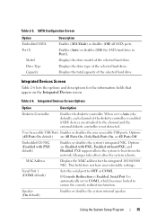
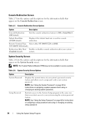
...) Enables or disables the system's integrated NIC. PXE support allows the system to OFF or COM1. Serial Port 1 (COM1 default) Sets the serial port to boot from the network. Using the System Setup Program 35 Displays the drive type of the selected hard drive. User Accessible USB Ports Enables or disables...
...) Enables or disables the system's integrated NIC. PXE support allows the system to OFF or COM1. Serial Port 1 (COM1 default) Sets the serial port to boot from the network. Using the System Setup Program 35 Displays the drive type of the selected hard drive. User Accessible USB Ports Enables or disables...
Hardware Owner's Manual
Page 36
... that appear on the System Security screen. Remote Terminal Type Select either VT 100/VT 220 or ANSI. (VT 100/VT 220 default) Redirection After Boot Enables or disables console redirection after your system using the system password feature. NOTE: The Trusted Platform Module (TPM) may not be available in the...
... that appear on the System Security screen. Remote Terminal Type Select either VT 100/VT 220 or ANSI. (VT 100/VT 220 default) Redirection After Boot Enables or disables console redirection after your system using the system password feature. NOTE: The Trusted Platform Module (TPM) may not be available in the...
Hardware Owner's Manual
Page 37
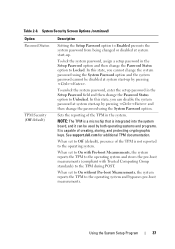
... be used by pressing . In this state, you can be disabled at system start-up. See support.dell.com for additional TPM documentation. When set to On without Pre-boot Measurements, the system reports the TPM to the TPM during POST. Sets the reporting of the TPM is ... by pressing and then change the system password using the System Password option. When set to On with Pre-boot Measurements, the system reports the TPM to the operating system and stores the pre-boot measurements (compliant with Trusted Computing Group standards) to the operating system and bypasses pre...
... be used by pressing . In this state, you can be disabled at system start-up. See support.dell.com for additional TPM documentation. When set to On without Pre-boot Measurements, the system reports the TPM to the TPM during POST. Sets the reporting of the TPM is ... by pressing and then change the system password using the System Password option. When set to On with Pre-boot Measurements, the system reports the TPM to the operating system and stores the pre-boot measurements (compliant with Trusted Computing Group standards) to the operating system and bypasses pre...

Hardware Owner's Manual
Page 38
.... AC Power Recovery (Last default) Determines how the system reacts when power is restored. Table 2-8. TPM Clear (No default) NOTICE: Clearing the TPM will prevent booting to Off. Be sure to back up the TPM keys prior to the system.
.... AC Power Recovery (Last default) Determines how the system reacts when power is restored. Table 2-8. TPM Clear (No default) NOTICE: Clearing the TPM will prevent booting to Off. Be sure to back up the TPM keys prior to the system.
Hardware Owner's Manual
Page 116
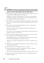
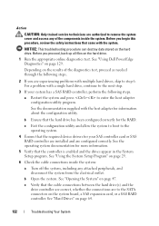
... the memory modules in the System Setup program, proceed to power. 3 Turn on the system and attached peripherals and, as the system boots, note the messages on page 47. 7 Ensure that the memory banks are authorized to remove the system cover and access any other system...Program" on page 75. See "Installing a Memory Module" on page 129. Action CAUTION: Only trained service technicians are populated correctly. See "Using Dell PowerEdge Diagnostics" on page 77. 116 Troubleshooting Your System If an error messages appears indicating a fault with the system. 1 If the system is not...
... the memory modules in the System Setup program, proceed to power. 3 Turn on the system and attached peripherals and, as the system boots, note the messages on page 47. 7 Ensure that the memory banks are authorized to remove the system cover and access any other system...Program" on page 75. See "Installing a Memory Module" on page 129. Action CAUTION: Only trained service technicians are populated correctly. See "Using Dell PowerEdge Diagnostics" on page 77. 116 Troubleshooting Your System If an error messages appears indicating a fault with the system. 1 If the system is not...
Hardware Owner's Manual
Page 117
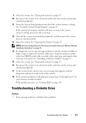
... diagnostic indicators on page 47. 16 Reconnect the system to its electrical outlet, and turn on the system and attached peripherals. 17 As the system boots, observe any error message that is still indicated, repeat step 12 through step 17 for the memory modules exist; See "Closing the System" on page...
... diagnostic indicators on page 47. 16 Reconnect the system to its electrical outlet, and turn on the system and attached peripherals. 17 As the system boots, observe any error message that is still indicated, repeat step 12 through step 17 for the memory modules exist; See "Closing the System" on page...

Hardware Owner's Manual
Page 119
... correctly. Before you begin this procedure, review the safety instructions that you removed in an optical drive. • Optical drive indicator does not blink during boot. If the tests run successfully, an expansion card may be faulty. See "Installing an Expansion Card" on page 139. 17 Turn off the system and...
... correctly. Before you begin this procedure, review the safety instructions that you removed in an optical drive. • Optical drive indicator does not blink during boot. If the tests run successfully, an expansion card may be faulty. See "Installing an Expansion Card" on page 139. 17 Turn off the system and...
Hardware Owner's Manual
Page 122
... that the cable connections between the hard drive(s) and the drive controller are correct, whether the connections are configured correctly. See "Using Dell PowerEdge Diagnostics" on page 47. a Restart the system and press to step 6. See the operating system documentation for more information. 5 Verify...Hard Drives" on page 29. 6 Check the cable connections inside the system. c Exit the configuration utility and allow the system to boot to the operating system. 4 Ensure that came with multiple hard drives, skip to enter the host adapter configuration utility program. See "Using...
... that the cable connections between the hard drive(s) and the drive controller are correct, whether the connections are configured correctly. See "Using Dell PowerEdge Diagnostics" on page 47. a Restart the system and press to step 6. See the operating system documentation for more information. 5 Verify...Hard Drives" on page 29. 6 Check the cable connections inside the system. c Exit the configuration utility and allow the system to boot to the operating system. 4 Ensure that came with multiple hard drives, skip to enter the host adapter configuration utility program. See "Using...

Hardware Owner's Manual
Page 130
Running the System Diagnostics The system diagnostics is displayed stating that program). 1 As the system boots, press during testing. NOTICE: Use the system diagnostics to help identify the problem. When you start the system diagnostics so that inform you of testing ...
Running the System Diagnostics The system diagnostics is displayed stating that program). 1 As the system boots, press during testing. NOTICE: Use the system diagnostics to help identify the problem. When you start the system diagnostics so that inform you of testing ...

Hardware Owner's Manual
Page 134
... of the system board connectors. 134 Jumpers and Connectors System Board Connectors CAUTION: Only trained service technicians are retained at next system boot. Before you begin this procedure, review the safety instructions that came with the system. System Board Jumper Settings Jumper Setting Description PWRD_EN... (default) The password feature is disabled. NVRAM_CLR (default) The configuration settings in NVRAM are cleared at system boot. See Figure 6-2 and Table 6-2 for the location and description of the components inside the system. Table 6-1.
... of the system board connectors. 134 Jumpers and Connectors System Board Connectors CAUTION: Only trained service technicians are retained at next system boot. Before you begin this procedure, review the safety instructions that came with the system. System Board Jumper Settings Jumper Setting Description PWRD_EN... (default) The password feature is disabled. NVRAM_CLR (default) The configuration settings in NVRAM are cleared at system boot. See Figure 6-2 and Table 6-2 for the location and description of the components inside the system. Table 6-1.

Hardware Owner's Manual
Page 137
... system board. 4 Close the system. CAUTION: Only trained service technicians are not disabled (erased) until the system boots with the jumper plug still removed, the system disables the new password(s) the next time it boots. 6 Turn off the system and attached peripherals, and disconnect the system from the electrical outlet. 7 Open the...
... system board. 4 Close the system. CAUTION: Only trained service technicians are not disabled (erased) until the system boots with the jumper plug still removed, the system disables the new password(s) the next time it boots. 6 Turn off the system and attached peripherals, and disconnect the system from the electrical outlet. 7 Open the...

Hardware Owner's Manual
Page 142
...fails to a disk drive for the peripheral devices connected to running in the cache, the disk-cache utility can reboot (also called warm boot) your system. Each component is used to communicate with DMI. coprocessor - Otherwise, you start your system. When a program makes a ...from the disk drive. Centimeter(s). COM - The first 640 KB of groups and attributes that are compatible with controllers for data that component. boot routine - bus - CD - cache - component - controller - Your system also contains an address bus and a data bus for communications between...
...fails to a disk drive for the peripheral devices connected to running in the cache, the disk-cache utility can reboot (also called warm boot) your system. Each component is used to communicate with DMI. coprocessor - Otherwise, you start your system. When a program makes a ...from the disk drive. Centimeter(s). COM - The first 640 KB of groups and attributes that are compatible with controllers for data that component. boot routine - bus - CD - cache - component - controller - Your system also contains an address bus and a data bus for communications between...
Hardware Owner's Manual
Page 146
...,576 bits. Mbps - KMM - KVM refers to the system board. 146 Glossary See also bus. Meter(s). Media Access Control address. Mb - Megabytes per second. Master boot record. A small circuit board containing DRAM chips that runs on a network. An operating system similar to the UNIX® operating system that connects to a switch...
...,576 bits. Mbps - KMM - KVM refers to the system board. 146 Glossary See also bus. Meter(s). Media Access Control address. Mb - Megabytes per second. Master boot record. A small circuit board containing DRAM chips that runs on a network. An operating system similar to the UNIX® operating system that connects to a switch...


