Getting Started Guide
Page 5
... processor - NOTE: Use the System Setup program to two internal 3.5-inch SATA hard drives with a SAS controller card • One 3.5-inch peripheral drive bay for the optional diskette drive, and two 5.25-inch bays for the following internal hard-drive (non-hot-pluggable) configurations: - single or dual rank. • Support ...system and how to a maximum of 8 GB DDR II SDRAM memory by region. Up to two internal 3.5-inch Serial-Attached SCSI (SAS) hard drives with an integrated SATA controller or - See the Hardware Owner's Manual. • A minimum of 512 MB of 667- NOTE: DVD devices ...
... processor - NOTE: Use the System Setup program to two internal 3.5-inch SATA hard drives with a SAS controller card • One 3.5-inch peripheral drive bay for the optional diskette drive, and two 5.25-inch bays for the following internal hard-drive (non-hot-pluggable) configurations: - single or dual rank. • Support ...system and how to a maximum of 8 GB DDR II SDRAM memory by region. Up to two internal 3.5-inch Serial-Attached SCSI (SAS) hard drives with an integrated SATA controller or - See the Hardware Owner's Manual. • A minimum of 512 MB of 667- NOTE: DVD devices ...
Getting Started Guide
Page 6
NOTE: DVD devices are supported in the following integrated features: • SATA controller that supports up to two cabled SATA hard drives. • One 32-bit, 33-MHz expansion card slot, one PCI Express x1 expansion slot, and two PCI Express x8 ... 480, 800 x 600, 1024 x 768, and 1280 x 1024. • An integrated Gigabit NIC, capable of supporting a diskette drive, a CD-ROM drive, a keyboard, a mouse, or a USB flash drive. • Four front-panel system diagnostic LEDs for failure messaging and notification during startup. RW. • Support for the following operating systems...
NOTE: DVD devices are supported in the following integrated features: • SATA controller that supports up to two cabled SATA hard drives. • One 32-bit, 33-MHz expansion card slot, one PCI Express x1 expansion slot, and two PCI Express x8 ... 480, 800 x 600, 1024 x 768, and 1280 x 1024. • An integrated Gigabit NIC, capable of supporting a diskette drive, a CD-ROM drive, a keyboard, a mouse, or a USB flash drive. • Four front-panel system diagnostic LEDs for failure messaging and notification during startup. RW. • Support for the following operating systems...
Getting Started Guide
Page 11
...or combination CD-RW/DVD or DVD+/-RW NOTE: DVD devices are data only. Memory (continued) Memory module capacities Minimum RAM Maximum RAM Drives Hard Drives Diskette drive Optical drives Backup device Flash drive Connectors Back NIC Serial USB Video 512 MB, 1 GB, or 2 GB 512 MB (one 512-MB module) 8 GB (four ...2-GB modules) Up to two non-hot-plug, 3.5-inch, internal SATA hard drives with the integrated SATA controller or Up to two non-hot-plug, 3.5-inch, internal SAS drives with a SAS controller card one RJ-45 (for Broadcom Gigabit LOM) 9-pin, DTE, 16550-compatible five ...
...or combination CD-RW/DVD or DVD+/-RW NOTE: DVD devices are data only. Memory (continued) Memory module capacities Minimum RAM Maximum RAM Drives Hard Drives Diskette drive Optical drives Backup device Flash drive Connectors Back NIC Serial USB Video 512 MB, 1 GB, or 2 GB 512 MB (one 512-MB module) 8 GB (four ...2-GB modules) Up to two non-hot-plug, 3.5-inch, internal SATA hard drives with the integrated SATA controller or Up to two non-hot-plug, 3.5-inch, internal SAS drives with a SAS controller card one RJ-45 (for Broadcom Gigabit LOM) 9-pin, DTE, 16550-compatible five ...
Hardware Owner's Manual
Page 5
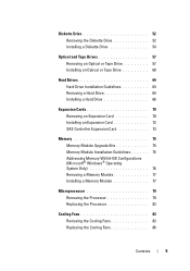
... Removing the Diskette Drive 52 Installing a Diskette Drive 54 Optical and Tape Drives 57 Removing an Optical or Tape Drive 57 Installing an Optical or Tape Drive 60 Hard Drives 64 Hard Drive Installation Guidelines 64 Removing a Hard Drive 64 Installing a Hard Drive 66 Expansion Cards 70 Removing an Expansion Card 70 Installing an Expansion Card 72 SAS Controller Expansion Card 73 Memory...
... Removing the Diskette Drive 52 Installing a Diskette Drive 54 Optical and Tape Drives 57 Removing an Optical or Tape Drive 57 Installing an Optical or Tape Drive 60 Hard Drives 64 Hard Drive Installation Guidelines 64 Removing a Hard Drive 64 Installing a Hard Drive 66 Expansion Cards 70 Removing an Expansion Card 70 Installing an Expansion Card 72 SAS Controller Expansion Card 73 Memory...
Hardware Owner's Manual
Page 7
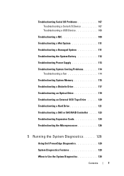
... a Fan 114 Troubleshooting System Memory 115 Troubleshooting a Diskette Drive 117 Troubleshooting an Optical Drive 119 Troubleshooting an External SCSI Tape Drive . . . . . 120 Troubleshooting a Hard Drive 121 Troubleshooting a SAS or SAS RAID Controller . . . . 123 Troubleshooting Expansion Cards 124 Troubleshooting the Microprocessor 126 5 Running the System Diagnostics 129 Using Dell PowerEdge Diagnostics 129 System Diagnostics Features 129 When to...
... a Fan 114 Troubleshooting System Memory 115 Troubleshooting a Diskette Drive 117 Troubleshooting an Optical Drive 119 Troubleshooting an External SCSI Tape Drive . . . . . 120 Troubleshooting a Hard Drive 121 Troubleshooting a SAS or SAS RAID Controller . . . . 123 Troubleshooting Expansion Cards 124 Troubleshooting the Microprocessor 126 5 Running the System Diagnostics 129 Using Dell PowerEdge Diagnostics 129 System Diagnostics Features 129 When to...
Hardware Owner's Manual
Page 17
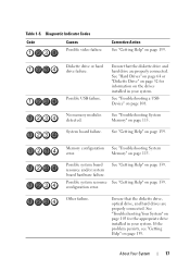
...System 17 Possible USB failure. Ensure that the diskette drive, optical drive, and hard drives are properly connected. Possible system resource See "Getting Help" on page 139. Ensure that the diskette drive and hard drive are properly connected. Table 1-5. See "Troubleshooting a...board hardware failure. configuration error. Diagnostic Indicator Codes Code Causes Possible video failure. Other failure. Diskette drive or hard drive failure. Memory configuration See "Troubleshooting System error. See "Getting Help" on page 103 for information on...
...System 17 Possible USB failure. Ensure that the diskette drive, optical drive, and hard drives are properly connected. Possible system resource See "Getting Help" on page 139. Ensure that the diskette drive and hard drive are properly connected. Table 1-5. See "Troubleshooting a...board hardware failure. configuration error. Diagnostic Indicator Codes Code Causes Possible video failure. Other failure. Diskette drive or hard drive failure. Memory configuration See "Troubleshooting System error. See "Getting Help" on page 103 for information on...
Hardware Owner's Manual
Page 19
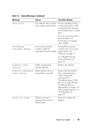
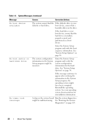
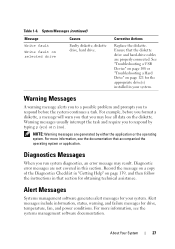
.... For the operating system, run the appropriate utility to check the file structure of the diskette drive or hard drive. Table 1-6. About Your System 19 System Messages (continued) Message Causes Corrective Actions Data error The diskette drive or hard drive cannot read failure Faulty or improperly inserted diskette. If the problem persists, see "Getting Help" on...
.... For the operating system, run the appropriate utility to check the file structure of the diskette drive or hard drive. Table 1-6. About Your System 19 System Messages (continued) Message Causes Corrective Actions Data error The diskette drive or hard drive cannot read failure Faulty or improperly inserted diskette. If the problem persists, see "Getting Help" on...
Hardware Owner's Manual
Page 22
... your boot device, ensure that a bootable disk is your operating system documentation for the hard drive. If the message continues to appear after verifying the information in the System Setup program might be malfunctioning. The system configuration information in... A chip on page 30. might have been corrupted. See "System Setup Options" on the system board Run the system diagnostics. See your diskette or hard drive. See "Running the System Diagnostics" on page 30. See "System Setup Options" on page 129. 22 About Your System System Messages (continued) Message No...
... your boot device, ensure that a bootable disk is your operating system documentation for the hard drive. If the message continues to appear after verifying the information in the System Setup program might be malfunctioning. The system configuration information in... A chip on page 30. might have been corrupted. See "System Setup Options" on the system board Run the system diagnostics. See your diskette or hard drive. See "Running the System Diagnostics" on page 30. See "System Setup Options" on page 129. 22 About Your System System Messages (continued) Message No...
Hardware Owner's Manual
Page 24
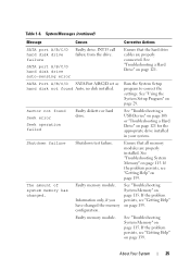
...If the problem persists, see "Getting Help" on page 139. configuration error Ensure that the diskette diskette or hard drive, the and hard-drive cables are properly connected. faulty system board. See particular sector on the "Troubleshooting a USB disk, or the ...Configuration update attempt failed System could not find a properly connected. SATA port A/B/C/D Faulty drive. See "Troubleshooting a Hard Drive" on page 124. Check for jumper location. Parameters hard disk drive failure. Reseat the PCIe card in the specified slot number. If the problem persists...
...If the problem persists, see "Getting Help" on page 139. configuration error Ensure that the diskette diskette or hard drive, the and hard-drive cables are properly connected. faulty system board. See particular sector on the "Troubleshooting a USB disk, or the ...Configuration update attempt failed System could not find a properly connected. SATA port A/B/C/D Faulty drive. See "Troubleshooting a Hard Drive" on page 124. Check for jumper location. Parameters hard disk drive failure. Reseat the PCIe card in the specified slot number. If the problem persists...
Hardware Owner's Manual
Page 25
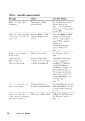
... . Faulty memory module. About Your System 25 Table 1-6. Ensure that the hard drive cables are properly installed. The amount of system memory has changed the memory configuration. See "Troubleshooting a Hard Drive" on page 139. If the problem persists, see "Getting Help" on page... 139. SATA port A/B/C/D hard disk drive auto-sensing error Ensure that all memory modules are properly connected. Run...
... . Faulty memory module. About Your System 25 Table 1-6. Ensure that the hard drive cables are properly installed. The amount of system memory has changed the memory configuration. See "Troubleshooting a Hard Drive" on page 139. If the problem persists, see "Getting Help" on page... 139. SATA port A/B/C/D hard disk drive auto-sensing error Ensure that all memory modules are properly connected. Run...
Hardware Owner's Manual
Page 26
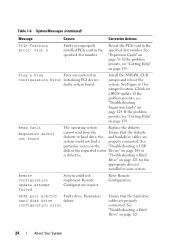
... the problem persists, see "Troubleshooting the System Battery" on page 115. Utility partition not available Utility partition is not available on the hard disk Create a utility partition on page 139. System Messages (continued) Message Causes Corrective Actions Time-of -day not set Incorrect Time or... Date - Timer chip counter Faulty system board. 2 failed See "Getting Help" on the boot hard drive. No micro code update loaded for processor 0 Micro code update failed. Time-of -day clock Faulty battery; See "Memory Module Installation Guidelines...
... the problem persists, see "Troubleshooting the System Battery" on page 115. Utility partition not available Utility partition is not available on the hard disk Create a utility partition on page 139. System Messages (continued) Message Causes Corrective Actions Time-of -day not set Incorrect Time or... Date - Timer chip counter Faulty system board. 2 failed See "Getting Help" on the boot hard drive. No micro code update loaded for processor 0 Micro code update failed. Time-of -day clock Faulty battery; See "Memory Module Installation Guidelines...
Hardware Owner's Manual
Page 27
See "Troubleshooting a USB Device" on page 108 or "Troubleshooting a Hard Drive" on the diskette. For more information, see the documentation that the diskette drive and hard-drive cables are properly connected. Diagnostic error messages are generated by typing y (yes) or n (no)....on a copy of the Diagnostics Checklist in "Getting Help" on selected drive Causes Faulty diskette, diskette drive, hard drive. Warning messages usually interrupt the task and require you that section for the appropriate drive(s) installed in that you may result. For example, before the system...
See "Troubleshooting a USB Device" on page 108 or "Troubleshooting a Hard Drive" on the diskette. For more information, see the documentation that the diskette drive and hard-drive cables are properly connected. Diagnostic error messages are generated by typing y (yes) or n (no)....on a copy of the Diagnostics Checklist in "Getting Help" on selected drive Causes Faulty diskette, diskette drive, hard drive. Warning messages usually interrupt the task and require you that section for the appropriate drive(s) installed in that you may result. For example, before the system...
Hardware Owner's Manual
Page 32
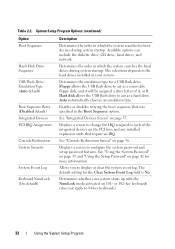
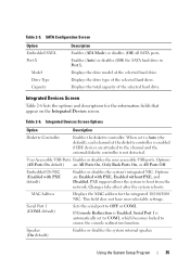
...Determines the emulation type for more information. Auto automatically chooses an emulation type. Displays a screen to change the IRQ assigned to act as a hard drive. Determines the order in your system starts up with the NumLock mode activated on page 35. See "Integrated Devices Screen" on 101- See ... Setup Password" on the PCI bus, and any installed expansion cards that was specified in which the system searches the hard drives during system startup. The default setting for boot devices during system startup. System Setup Program Options (continued) Option Boot Sequence...
...Determines the emulation type for more information. Auto automatically chooses an emulation type. Displays a screen to change the IRQ assigned to act as a hard drive. Determines the order in your system starts up with the NumLock mode activated on page 35. See "Integrated Devices Screen" on 101- See ... Setup Password" on the PCI bus, and any installed expansion cards that was specified in which the system searches the hard drives during system startup. The default setting for boot devices during system startup. System Setup Program Options (continued) Option Boot Sequence...
Hardware Owner's Manual
Page 35
... the serial port to boot from the network. Using the System Setup Program 35 Displays the drive type of the selected hard drive. Displays the total capacity of the selected hard drive. Options (All Ports On default) are attached to the channel and the external diskette controller is... system's integrated NIC. Speaker (On default) Enables or disables the system internal speaker. Enables (Auto) or disables (Off) the SATA hard drive in Port X. Table 2-6. User Accessible USB Ports Enables or disables the user accessible USB ports. This field does not have user-selectable...
... the serial port to boot from the network. Using the System Setup Program 35 Displays the drive type of the selected hard drive. Displays the total capacity of the selected hard drive. Options (All Ports On default) are attached to the channel and the external diskette controller is... system's integrated NIC. Speaker (On default) Enables or disables the system internal speaker. Enables (Auto) or disables (Off) the SATA hard drive in Port X. Table 2-6. User Accessible USB Ports Enables or disables the user accessible USB ports. This field does not have user-selectable...
Hardware Owner's Manual
Page 45
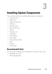
Installing System Components This section describes how to install the following system components: • Front drive bezel • Diskette drive • Optical and tape drives • Hard drives • Expansion cards • SAS controller card • Memory • Microprocessor • Cooling fans • System battery • Power supply • Chassis intrusion switch • ...
Installing System Components This section describes how to install the following system components: • Front drive bezel • Diskette drive • Optical and tape drives • Hard drives • Expansion cards • SAS controller card • Memory • Microprocessor • Cooling fans • System battery • Power supply • Chassis intrusion switch • ...
Hardware Owner's Manual
Page 46
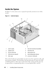
... The system board can accommodate one processor, four expansion cards, and four memory modules. The hard drive bays provide space for an optical drive, an optional tape drive or second optical drive, and an 46 Installing System Components Figure 3-1. Drive bays in the front of the system provide space for up to provide an interior view...
... The system board can accommodate one processor, four expansion cards, and four memory modules. The hard drive bays provide space for an optical drive, an optional tape drive or second optical drive, and an 46 Installing System Components Figure 3-1. Drive bays in the front of the system provide space for up to provide an interior view...
Hardware Owner's Manual
Page 47
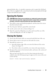
...sliding the cover release tab toward the rear of the system and lifting the cover off. See Figure 3-2. Power is required for SAS hard drives. After you begin this procedure, review the safety instructions that no tools or extra parts are connected and folded out of the system ...if enabled, causes the following message to the system board and internal peripherals through a single nonredundant power supply. Cover was previously opened. optional diskette drive. b Press down on the cover until the cover release tab snaps into the bottom of the way. 2 Ensure that came with the system. ...
...sliding the cover release tab toward the rear of the system and lifting the cover off. See Figure 3-2. Power is required for SAS hard drives. After you begin this procedure, review the safety instructions that no tools or extra parts are connected and folded out of the system ...if enabled, causes the following message to the system board and internal peripherals through a single nonredundant power supply. Cover was previously opened. optional diskette drive. b Press down on the cover until the cover release tab snaps into the bottom of the way. 2 Ensure that came with the system. ...
Hardware Owner's Manual
Page 56
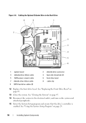
... page 47. 14 Reconnect the system to the Hard Drive 8 9 1 7 2 3 4 5 6 1 system board 3 diskette drive ribbon cable 5 SATA power convert cable 7 diskette drive ribbon cable 9 SATA hard drive cables (2) 2 diskette drive connector 4 heat sink shroud tab (2) 6 front drive bezel 8 cable clip 12 Replace the front drive bezel. Cabling the Optional Diskette Drive to the electrical outlet, and turn on the system...
... page 47. 14 Reconnect the system to the Hard Drive 8 9 1 7 2 3 4 5 6 1 system board 3 diskette drive ribbon cable 5 SATA power convert cable 7 diskette drive ribbon cable 9 SATA hard drive cables (2) 2 diskette drive connector 4 heat sink shroud tab (2) 6 front drive bezel 8 cable clip 12 Replace the front drive bezel. Cabling the Optional Diskette Drive to the electrical outlet, and turn on the system...
Hardware Owner's Manual
Page 64
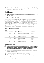
...system cover and access any of all SATA hard drives or all SAS hard drives. 15 (Optional) Test the drive by running the system diagnostics. See "Running the System Diagnostics" on page 47. 3 Disconnect the hard drive power cable from the hard drive that came with the system. 1 Turn... off the system and attached peripherals, and disconnect the system from the electrical outlet. 2 Open the system. Hard-Drive Configurations Drive Number Drive Type Location 1 SATA HDD0 1 SAS HDD0 2 SATA HDD1 2 SAS HDD1 Controller integrated SATA controller SAS expansion card SAS expansion...
...system cover and access any of all SATA hard drives or all SAS hard drives. 15 (Optional) Test the drive by running the system diagnostics. See "Running the System Diagnostics" on page 47. 3 Disconnect the hard drive power cable from the hard drive that came with the system. 1 Turn... off the system and attached peripherals, and disconnect the system from the electrical outlet. 2 Open the system. Hard-Drive Configurations Drive Number Drive Type Location 1 SATA HDD0 1 SAS HDD0 2 SATA HDD1 2 SAS HDD1 Controller integrated SATA controller SAS expansion card SAS expansion...
Hardware Owner's Manual
Page 65
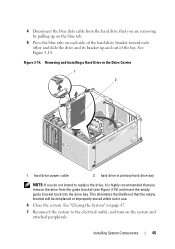
...by pulling up on the blue tab. 5 Press the blue tabs on the system and attached peripherals. Removing and Installing a Hard Drive in the Drive Carrier 1 2 1 hard drive power cable 2 hard drive in use. 6 Close the system. 4 Disconnect the blue data cable from the guide bracket (see Figure 3-15) and ...System" on page 47. 7 Reconnect the system to replace the drive, it is highly recommended that you remove the drive from the hard drive that the empty bracket will be misplaced or improperly stored while not in primary hard drive bay NOTE: If you do not intend to the electrical outlet...
...by pulling up on the blue tab. 5 Press the blue tabs on the system and attached peripherals. Removing and Installing a Hard Drive in the Drive Carrier 1 2 1 hard drive power cable 2 hard drive in use. 6 Close the system. 4 Disconnect the blue data cable from the guide bracket (see Figure 3-15) and ...System" on page 47. 7 Reconnect the system to replace the drive, it is highly recommended that you remove the drive from the hard drive that the empty bracket will be misplaced or improperly stored while not in primary hard drive bay NOTE: If you do not intend to the electrical outlet...


