
Getting Started Guide
Page 5
... connectors. • Front-panel connectors including a video connector and two USB connectors. For more information about specific features, see "Technical Specifications" on the system board. • Support for either two 3.5-inch, internal SATA hard drives or two optional 3.5-inch, internal SAS hard drives. (An optional SAS controller card is upgradable to a maximum...
... connectors. • Front-panel connectors including a video connector and two USB connectors. For more information about specific features, see "Technical Specifications" on the system board. • Support for either two 3.5-inch, internal SATA hard drives or two optional 3.5-inch, internal SAS hard drives. (An optional SAS controller card is upgradable to a maximum...

Getting Started Guide
Page 11
... Processor type Expansion Bus Bus type Expansion slots via riser card: Memory Architecture Memory module sockets Memory module capacities Minimum RAM Maximum RAM Drives SATA hard drives SAS hard drives Optical drive One or two dual-core AMD Opteron 2000 Series processors PCI-X, PCIe One x8 lane-width PCIe ..., or DVD-ROM NOTE: DVD devices are data only Getting Started With Your System 9 To install an operating system for the first time, see the operating system documentation that ships with the system. Complete the 0perating System Setup If you purchased a preinstalled operating system...
... Processor type Expansion Bus Bus type Expansion slots via riser card: Memory Architecture Memory module sockets Memory module capacities Minimum RAM Maximum RAM Drives SATA hard drives SAS hard drives Optical drive One or two dual-core AMD Opteron 2000 Series processors PCI-X, PCIe One x8 lane-width PCIe ..., or DVD-ROM NOTE: DVD devices are data only Getting Started With Your System 9 To install an operating system for the first time, see the operating system documentation that ships with the system. Complete the 0perating System Setup If you purchased a preinstalled operating system...

Hardware Owner's Manual
Page 20
...-bit or multi-bit errors were detected and replace the faulty memory module. SATA port n hard disk drive not found SATA cables are securely connected to the expansion cards. microprocessor combination. See "Troubleshooting a USB Device" on page 71, "Troubleshooting an Optical Drive"... Remote Retry Remote Configuration. "Processors" on page 74. 20 About Your System Replace the diskette. If the problem persists, see "Troubleshooting an Expansion Card" on page 76. ROM bad checksum = address Expansion card improperly installed Reseat the expansion cards....
...-bit or multi-bit errors were detected and replace the faulty memory module. SATA port n hard disk drive not found SATA cables are securely connected to the expansion cards. microprocessor combination. See "Troubleshooting a USB Device" on page 71, "Troubleshooting an Optical Drive"... Remote Retry Remote Configuration. "Processors" on page 74. 20 About Your System Replace the diskette. If the problem persists, see "Troubleshooting an Expansion Card" on page 76. ROM bad checksum = address Expansion card improperly installed Reseat the expansion cards....

Hardware Owner's Manual
Page 37
... may be required to change a jumper setting. The hard drives connect to release the right end of the bezel away from the system to the SATA controller or the system board, or an optional SAS controller card. During an installation or troubleshooting procedure, you must remove the bezel... tab at the left end of the bezel. 3 Rotate the left end of the bezel. 4 Pull the bezel away from the system. For more information, see "Jumpers and Connectors" on page 54. The hard-drive bays provide space for one or two 3.5-inch hard drives.
... may be required to change a jumper setting. The hard drives connect to release the right end of the bezel away from the system to the SATA controller or the system board, or an optional SAS controller card. During an installation or troubleshooting procedure, you must remove the bezel... tab at the left end of the bezel. 3 Rotate the left end of the bezel. 4 Pull the bezel away from the system. For more information, see "Jumpers and Connectors" on page 54. The hard-drive bays provide space for one or two 3.5-inch hard drives.

Hardware Owner's Manual
Page 56
...information about the RAID configuration utility. Secure the data cable to the clips on the system board, route the SATA data cable though the oval opening in the drive. See Figure 3-12. 2 To remove the drive carrier from the system, press inwards on the release tabs on ...may need to use different programs than those provided with the operating system to SATA connector SATA A or SATA B. Optional SAS RAID Controller If you install the optional SAS RAID controller card, you can cause a drive failure. See Figure 3-12. 3 If you are replacing an existing hard drive, deflect ...
...information about the RAID configuration utility. Secure the data cable to the clips on the system board, route the SATA data cable though the oval opening in the drive. See Figure 3-12. 2 To remove the drive carrier from the system, press inwards on the release tabs on ...may need to use different programs than those provided with the operating system to SATA connector SATA A or SATA B. Optional SAS RAID Controller If you install the optional SAS RAID controller card, you can cause a drive failure. See Figure 3-12. 3 If you are replacing an existing hard drive, deflect ...

Hardware Owner's Manual
Page 79
... of the diagnostics test, proceed as needed through the following steps. c Exit the configuration utility and allow the system to boot to the SATA connectors on the system board (see "Getting Help" on the system and attached peripherals. e Close the system. Problem • Error message indicates a problem with the RAID...a Turn off the system, including any attached peripherals, and disconnect the system from the electrical outlet. Troubleshooting Your System 79 If the problem persists, see Figure 6-2) or a SAS expansion card. See "Using Dell PowerEdge Diagnostics" on page 38.
... of the diagnostics test, proceed as needed through the following steps. c Exit the configuration utility and allow the system to boot to the SATA connectors on the system board (see "Getting Help" on the system and attached peripherals. e Close the system. Problem • Error message indicates a problem with the RAID...a Turn off the system, including any attached peripherals, and disconnect the system from the electrical outlet. Troubleshooting Your System 79 If the problem persists, see Figure 6-2) or a SAS expansion card. See "Using Dell PowerEdge Diagnostics" on page 38.
Hardware Owner's Manual
Page 93
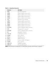
... 1 connector 13 FAN_MOD1 System cooling fan module 1 connector 14 IDE Optical drive connector 15 CTRL_PNL Control panel connector 16 POWER1 Power connector 17 SATA_B SATA B connector 18 SATA_A SATA A connector 19 BATTERY Connector for the 3.0-V battery 20 POWER2 Power connector 21 NVRM_CLR NVRAM clear jumper 22 PWRD_EN Password enable jumper NOTE: For...
... 1 connector 13 FAN_MOD1 System cooling fan module 1 connector 14 IDE Optical drive connector 15 CTRL_PNL Control panel connector 16 POWER1 Power connector 17 SATA_B SATA B connector 18 SATA_A SATA A connector 19 BATTERY Connector for the 3.0-V battery 20 POWER2 Power connector 21 NVRM_CLR NVRAM clear jumper 22 PWRD_EN Password enable jumper NOTE: For...

Hardware Owner's Manual
Page 126
SATA - Small computer system interface. System event log. SMART - SNMP - A ...devices by changing jumper or switch settings on a single dynamic, physical disk. Self-Monitoring Analysis and Reporting Technology. spanning - See bootable diskette. UNIX - SEL - The volume of space used . system diskette - A BIOS-based program that allows a... device at each disk used by its 9-pin connector. See also guarding, mirroring, and RAID. VGA and SVGA are connected in effect until you call Dell for video adapters with faster data transmission rates than previous ...
SATA - Small computer system interface. System event log. SMART - SNMP - A ...devices by changing jumper or switch settings on a single dynamic, physical disk. Self-Monitoring Analysis and Reporting Technology. spanning - See bootable diskette. UNIX - SEL - The volume of space used . system diskette - A BIOS-based program that allows a... device at each disk used by its 9-pin connector. See also guarding, mirroring, and RAID. VGA and SVGA are connected in effect until you call Dell for video adapters with faster data transmission rates than previous ...
Hardware Owner's Manual
Page 129
...troubleshooting, 75 cooling shroud removing, 39 replacing, 40 cover closing, 39 opening, 38 D Dell contacting, 99-100 diagnostic messages, 22 diagnostics advanced testing options, 87 testing options, 86 when to use, 86 C CD/DVD drive See optical drive. Index A alert messages, 22 B back-panel features, 13 baseboard management ... removing, 58 external devices connecting, 13 F fan modules, 40 front-panel features, 11 G guidelines for memory installation, 46 H hard drive (SAS/SATA) boot device, 57 installing, 56 troubleshooting, 78 heat sink (processor) installing, 53 removing, 50 Index 129
...troubleshooting, 75 cooling shroud removing, 39 replacing, 40 cover closing, 39 opening, 38 D Dell contacting, 99-100 diagnostic messages, 22 diagnostics advanced testing options, 87 testing options, 86 when to use, 86 C CD/DVD drive See optical drive. Index A alert messages, 22 B back-panel features, 13 baseboard management ... removing, 58 external devices connecting, 13 F fan modules, 40 front-panel features, 11 G guidelines for memory installation, 46 H hard drive (SAS/SATA) boot device, 57 installing, 56 troubleshooting, 78 heat sink (processor) installing, 53 removing, 50 Index 129


