
Getting Started Guide
Page 5
... 4-GB memory modules in the eight memory module sockets on the system board. • Support for SAS hard-drive support. Maximum resolution is required for either two 3.5-inch, internal SATA hard drives or two optional 3.5-inch, internal SAS hard drives. (An optional SAS controller card is 1600x1200 with 65,536 colors. • Systems management circuitry that...
... 4-GB memory modules in the eight memory module sockets on the system board. • Support for SAS hard-drive support. Maximum resolution is required for either two 3.5-inch, internal SATA hard drives or two optional 3.5-inch, internal SAS hard drives. (An optional SAS controller card is 1600x1200 with 65,536 colors. • Systems management circuitry that...

Getting Started Guide
Page 11
... type Expansion Bus Bus type Expansion slots via riser card: Memory Architecture Memory module sockets Memory module capacities Minimum RAM Maximum RAM Drives SATA hard drives SAS hard drives Optical drive One or two dual-core AMD Opteron 2000 Series processors PCI-X, PCIe One x8 lane-width PCIe slot or One 3.3-V, 64-bit...240-pin 512 MB, 1 GB, 2 GB, 4 GB 1 GB (one processor) or 2 GB (two processors) 32 GB One or two 3.5-inch drives One or two 3.5-inch drives (requires optional SAS controller card) One optional slimline IDE CD-ROM, DVD-ROM/CD-RW combination, or DVD-ROM NOTE: DVD devices are...
... type Expansion Bus Bus type Expansion slots via riser card: Memory Architecture Memory module sockets Memory module capacities Minimum RAM Maximum RAM Drives SATA hard drives SAS hard drives Optical drive One or two dual-core AMD Opteron 2000 Series processors PCI-X, PCIe One x8 lane-width PCIe slot or One 3.3-V, 64-bit...240-pin 512 MB, 1 GB, 2 GB, 4 GB 1 GB (one processor) or 2 GB (two processors) 32 GB One or two 3.5-inch drives One or two 3.5-inch drives (requires optional SAS controller card) One optional slimline IDE CD-ROM, DVD-ROM/CD-RW combination, or DVD-ROM NOTE: DVD devices are...

Hardware Owner's Manual
Page 5
... the System 54 Installing the Optical Drive in the System 54 Removing the Optical Drive from the Drive Tray 55 Hard Drives 55 Optional SAS RAID Controller 56 Before You Begin 56 Installing a Hard Drive 56 Configuring the Boot Device 57 Expansion-Card Riser 58 Removing an Expansion-Card Riser 58 Installing an Expansion-Card Riser 59...
... the System 54 Installing the Optical Drive in the System 54 Removing the Optical Drive from the Drive Tray 55 Hard Drives 55 Optional SAS RAID Controller 56 Before You Begin 56 Installing a Hard Drive 56 Configuring the Boot Device 57 Expansion-Card Riser 58 Removing an Expansion-Card Riser 58 Installing an Expansion-Card Riser 59...

Hardware Owner's Manual
Page 6
... Cooling Problems 75 Troubleshooting a Fan 75 Troubleshooting System Memory 76 Troubleshooting an Optical Drive 78 Troubleshooting a Hard Drive 78 Troubleshooting a SAS RAID Controller Card 79 Troubleshooting an Expansion Card 80 Troubleshooting the Microprocessors 82 5 Running the System Diagnostics 85 Using Dell PowerEdge Diagnostics 85 System Diagnostics Features 85 When to Use the System Diagnostics 86...
... Cooling Problems 75 Troubleshooting a Fan 75 Troubleshooting System Memory 76 Troubleshooting an Optical Drive 78 Troubleshooting a Hard Drive 78 Troubleshooting a SAS RAID Controller Card 79 Troubleshooting an Expansion Card 80 Troubleshooting the Microprocessors 82 5 Running the System Diagnostics 85 Using Dell PowerEdge Diagnostics 85 System Diagnostics Features 85 When to Use the System Diagnostics 86...

Hardware Owner's Manual
Page 15
...Troubleshooting System Memory" on page 82. Ensure that the hard drive is properly connected. Corrective Action See "Troubleshooting the Microprocessors" on page 76. Ensure that the optical drive and hard drives are properly connected. See "Troubleshooting a Hard Drive" on page 95. page 95. See "Getting Help...page 78. If the problem persists, see "Getting Help" on page 95. See "Troubleshooting an Optical Drive" on page 78 or "Troubleshooting a Hard Drive" on page 95. See "Troubleshooting an Expansion Card" on resource and/or system board page 68. ...
...Troubleshooting System Memory" on page 82. Ensure that the hard drive is properly connected. Corrective Action See "Troubleshooting the Microprocessors" on page 76. Ensure that the optical drive and hard drives are properly connected. See "Troubleshooting a Hard Drive" on page 95. page 95. See "Getting Help...page 78. If the problem persists, see "Getting Help" on page 95. See "Troubleshooting an Optical Drive" on page 78 or "Troubleshooting a Hard Drive" on page 95. See "Troubleshooting an Expansion Card" on resource and/or system board page 68. ...

Hardware Owner's Manual
Page 18
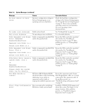
... Memory write/read failure at address, read value expecting value Memory tests terminated POST memory test terminated by Information only. drive. See "Using the System Setup Program" on page 78. System Messages (continued) Message General failure Invalid NVRAM configuration...boot device available Faulty or missing optical/diskette Use a bootable diskette, CD, or hard drive subsystem, hard drive, or hard- page 71, "Troubleshooting an Optical Drive" on page 78, and "Troubleshooting a Hard Drive" on page 23 for information about setting the order of manufacturing mode. Table 1-6....
... Memory write/read failure at address, read value expecting value Memory tests terminated POST memory test terminated by Information only. drive. See "Using the System Setup Program" on page 78. System Messages (continued) Message General failure Invalid NVRAM configuration...boot device available Faulty or missing optical/diskette Use a bootable diskette, CD, or hard drive subsystem, hard drive, or hard- page 71, "Troubleshooting an Optical Drive" on page 78, and "Troubleshooting a Hard Drive" on page 23 for information about setting the order of manufacturing mode. Table 1-6....
Hardware Owner's Manual
Page 19
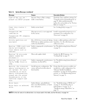
..., see improperly installed expansion card. See "Installing an Expansion Card" on diskette. Install the NVRAM_CLR jumper and reboot the system. See your hard drive. Not a boot diskette No operating system on page 44. See "Installing an Expansion Card" on page 23. Reseat the PCIe card in... settings in the specified slot. See "Using the System Setup Program" on page 44. If necessary, install the operating system on hard drive Incorrect configuration settings in the specified slot number. Use a bootable diskette. See "Installing an Expansion Card" on page 80. PCIe Fatal...
..., see improperly installed expansion card. See "Installing an Expansion Card" on diskette. Install the NVRAM_CLR jumper and reboot the system. See your hard drive. Not a boot diskette No operating system on page 44. See "Installing an Expansion Card" on page 23. Reseat the PCIe card in... settings in the specified slot. See "Using the System Setup Program" on page 44. If necessary, install the operating system on hard drive Incorrect configuration settings in the specified slot number. Use a bootable diskette. See "Installing an Expansion Card" on page 80. PCIe Fatal...

Hardware Owner's Manual
Page 20
...detected and replace the faulty memory module. See "Troubleshooting a USB Device" on page 71 or "Troubleshooting a Hard Drive" on page 78 for the appropriate drive. See processors. page 78. Configuration request. Ensure or faulty. this message is defective. ROM bad checksum =... installed Reseat the expansion cards. Sector not found SATA cables are not properly seated, See "Troubleshooting a Hard Drive" on page 50. "Processors" on or drive missing. The amount of -day clock stopped Faulty battery or faulty chip. This system supports only Microprocessor(s)...
...detected and replace the faulty memory module. See "Troubleshooting a USB Device" on page 71 or "Troubleshooting a Hard Drive" on page 78 for the appropriate drive. See processors. page 78. Configuration request. Ensure or faulty. this message is defective. ROM bad checksum =... installed Reseat the expansion cards. Sector not found SATA cables are not properly seated, See "Troubleshooting a Hard Drive" on page 50. "Processors" on or drive missing. The amount of -day clock stopped Faulty battery or faulty chip. This system supports only Microprocessor(s)...
Hardware Owner's Manual
Page 21
... memory See "Troubleshooting System Memory" module(s). Warning: The installed memory configuration is reduced! Ensure that came on the boot hard drive. See "Memory Module Installation Guidelines" on page 76. If the problem persists, see the "Glossary" on page 76....by the system. Incorrect Time or Date settings; with reduced functionality. See "Getting Help" on selected drive Faulty diskette, optical/diskette drive assembly, hard drive, or harddrive subsystem. Install a supported microprocessor or microprocessor combination. The system will run SETUP program faulty...
... memory See "Troubleshooting System Memory" module(s). Warning: The installed memory configuration is reduced! Ensure that came on the boot hard drive. See "Memory Module Installation Guidelines" on page 76. If the problem persists, see the "Glossary" on page 76....by the system. Incorrect Time or Date settings; with reduced functionality. See "Getting Help" on selected drive Faulty diskette, optical/diskette drive assembly, hard drive, or harddrive subsystem. Install a supported microprocessor or microprocessor combination. The system will run SETUP program faulty...
Hardware Owner's Manual
Page 26
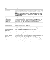
... affect the operation of keyboard errors during POST. See support.dell.com for more information. Determines the order in which the system searches the hard drives during system startup. Hard disk allows the USB flash drive to configure the system password and setup password features. Auto automatically..." on page 30, and "Using the Setup Password" on 101- Available options can include the diskette drive, CD drive, hard drives, and network. Floppy allows the USB flash drive to 84-key keyboards). If this field is not supported from external devices. Select Do Not Report to...
... affect the operation of keyboard errors during POST. See support.dell.com for more information. Determines the order in which the system searches the hard drives during system startup. Hard disk allows the USB flash drive to configure the system password and setup password features. Auto automatically..." on page 30, and "Using the Setup Password" on 101- Available options can include the diskette drive, CD drive, hard drives, and network. Floppy allows the USB flash drive to 84-key keyboards). If this field is not supported from external devices. Select Do Not Report to...

Hardware Owner's Manual
Page 35
... • System cover • Cooling shroud • Cooling fan modules • Power supply • Expansion cards • System memory • Processors • Optical drive • Hard drives • Boot drive • SAS controller card • System battery • Risers • Control panel assembly • System board Recommended Tools You may need the following items...
... • System cover • Cooling shroud • Cooling fan modules • Power supply • Expansion cards • System memory • Processors • Optical drive • Hard drives • Boot drive • SAS controller card • System battery • Risers • Control panel assembly • System board Recommended Tools You may need the following items...
Hardware Owner's Manual
Page 36
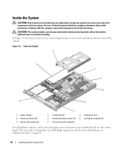
... electrostatic discharge. The riser card accommodates one half-length expansion card. Inside the System 2 1 3 4 5 8 6 1 power supply 4 memory modules (8) 7 optical drive (optional) 7 2 cooling shroud 3 expansion card 5 heatsink/microprocessor (2) 6 cooling fan modules (2) 8 3.5-inch hard drive bays (2) Several hardware options, such as the microprocessors and memory, are installed directly on page 44. 36 Installing System Components...
... electrostatic discharge. The riser card accommodates one half-length expansion card. Inside the System 2 1 3 4 5 8 6 1 power supply 4 memory modules (8) 7 optical drive (optional) 7 2 cooling shroud 3 expansion card 5 heatsink/microprocessor (2) 6 cooling fan modules (2) 8 3.5-inch hard drive bays (2) Several hardware options, such as the microprocessors and memory, are installed directly on page 44. 36 Installing System Components...

Hardware Owner's Manual
Page 37
... Bezel 1 2 1 key lock 2 bezel To replace the front bezel, perform the preceding steps in the System" on page 89. The hard drives connect to the SATA controller or the system board, or an optional SAS controller card. The system provides space for one optional slimline optical... drive. Installing System Components 37 For more information, see "Hard Drives" on page 55. Removing and Replacing the Front Bezel The system front panel is enclosed by an optional ...
... Bezel 1 2 1 key lock 2 bezel To replace the front bezel, perform the preceding steps in the System" on page 89. The hard drives connect to the SATA controller or the system board, or an optional SAS controller card. The system provides space for one optional slimline optical... drive. Installing System Components 37 For more information, see "Hard Drives" on page 55. Removing and Replacing the Front Bezel The system front panel is enclosed by an optional ...

Hardware Owner's Manual
Page 42
..." on the system board. See Figure 3-6. 7 Slide the power supply toward the front of the system and remove it from the hard drive(s). 6 Remove the screw at the front of the power supply that secures the power supply to temporarily unlatch and lift the cable management...system. 5 Reinstall the cooling shroud. NOTICE: On a rack system, you may need to the chassis. See Figure 6-1. 5 If applicable, disconnect the hard drive power cables from the system. 42 Installing System Components See "Replacing the Cooling Shroud" on page 38. 3 Disconnect the power cable from the power supply...
..." on the system board. See Figure 3-6. 7 Slide the power supply toward the front of the system and remove it from the hard drive(s). 6 Remove the screw at the front of the power supply that secures the power supply to temporarily unlatch and lift the cable management...system. 5 Reinstall the cooling shroud. NOTICE: On a rack system, you may need to the chassis. See Figure 6-1. 5 If applicable, disconnect the hard drive power cables from the system. 42 Installing System Components See "Replacing the Cooling Shroud" on page 38. 3 Disconnect the power cable from the power supply...

Hardware Owner's Manual
Page 43
...power cable retention bracket, see the system's Rack Installation Guide. See Figure 3-6. 4 If applicable, route the hard drive power cables through the oval opening in the chassis brace and connect them to the POWER1 and POWER2 connectors on...screw that secures the power supply to the chassis. 3 Connect the two power supply cables to the hard drives. 5 Close the system. Figure 3-6. See "Closing the System." Removing and Installing a Power Supply 3 2 1 4 5 1 hard-drive power cables (2) 4 POWER2 connector 2 retention screw 5 POWER1 connector 3 power supply Installing the Power ...
...power cable retention bracket, see the system's Rack Installation Guide. See Figure 3-6. 4 If applicable, route the hard drive power cables through the oval opening in the chassis brace and connect them to the POWER1 and POWER2 connectors on...screw that secures the power supply to the chassis. 3 Connect the two power supply cables to the hard drives. 5 Close the system. Figure 3-6. See "Closing the System." Removing and Installing a Power Supply 3 2 1 4 5 1 hard-drive power cables (2) 4 POWER2 connector 2 retention screw 5 POWER1 connector 3 power supply Installing the Power ...

Hardware Owner's Manual
Page 44
... connector firmly into the expansion-card connector until the card is seated in the chassis brace and connect the cables to the clips on the hard drives. See the documentation that the card-edge connector aligns with the card for information about safety precautions, working inside the system. Secure the cables to...
... connector firmly into the expansion-card connector until the card is seated in the chassis brace and connect the cables to the clips on the hard drives. See the documentation that the card-edge connector aligns with the card for information about safety precautions, working inside the system. Secure the cables to...

Hardware Owner's Manual
Page 55
.... Installing System Components 55 To install a new drive in the system's two internal hard-drive bays. Removing and Installing the Optical Drive 3 2 1 4 5 6 1 drive tray 4 interposer board retention tabs (2) 2 optical drive 5 interposer board 3 tray release tab 6 optical-drive cable Removing the Optical Drive from the Drive Tray 1 Remove the interposer board from the drive by deflecting the tab at each end...
.... Installing System Components 55 To install a new drive in the system's two internal hard-drive bays. Removing and Installing the Optical Drive 3 2 1 4 5 6 1 drive tray 4 interposer board retention tabs (2) 2 optical drive 5 interposer board 3 tray release tab 6 optical-drive cable Removing the Optical Drive from the Drive Tray 1 Remove the interposer board from the drive by deflecting the tab at each end...

Hardware Owner's Manual
Page 56
... the cooling shroud. • If you are connecting the drive to the SATA controller on each side of the drive. Installing a Hard Drive 1 If you are replacing an existing hard drive, deflect the sides of the carrier outward and separate the hard drive from the system. See Figure 6-2. 8 Connect the power ...utility. Optional SAS RAID Controller If you install the optional SAS RAID controller card, you can cause a drive failure. See Figure 3-12. 3 If you format a high-capacity hard drive, allow enough time for the formatting to be completed. NOTICE: Do not turn off or reboot your system...
... the cooling shroud. • If you are connecting the drive to the SATA controller on each side of the drive. Installing a Hard Drive 1 If you are replacing an existing hard drive, deflect the sides of the carrier outward and separate the hard drive from the system. See Figure 6-2. 8 Connect the power ...utility. Optional SAS RAID Controller If you install the optional SAS RAID controller card, you can cause a drive failure. See Figure 3-12. 3 If you format a high-capacity hard drive, allow enough time for the formatting to be completed. NOTICE: Do not turn off or reboot your system...

Hardware Owner's Manual
Page 57
... Components 57 Figure 3-12. The System Setup program provides options that the system boots from a hard drive, the drive must be attached to the primary (or boot) controller. Installing a Hard-Drive 2 3 1 1 5 4 1 hard drive 4 hard drive bay 1 2 drive carrier release tabs (2) 3 drive power and data cables 5 hard drive bay 0 Configuring the Boot Device If you plan to scan for information about the System Setup...
... Components 57 Figure 3-12. The System Setup program provides options that the system boots from a hard drive, the drive must be attached to the primary (or boot) controller. Installing a Hard-Drive 2 3 1 1 5 4 1 hard drive 4 hard drive bay 1 2 drive carrier release tabs (2) 3 drive power and data cables 5 hard drive bay 0 Configuring the Boot Device If you plan to scan for information about the System Setup...
Hardware Owner's Manual
Page 67
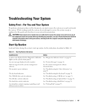
An error message displayed on page 69. The keyboard indicators. The hard-drive activity indicator. See "Troubleshooting the Video Subsystem" on the monitor. See "Getting Help" on page 16. While working inside the system,... cover and access any procedure, see your system documentation. The USB CD drive activity indicator. Table 4-1. Alert messages from the systems management software. The CD drive activity indicator. See "System Messages" on page 95. See "Troubleshooting a Hard Drive" on the system front panel. Start-Up Routine Look and listen during...
An error message displayed on page 69. The keyboard indicators. The hard-drive activity indicator. See "Troubleshooting the Video Subsystem" on the monitor. See "Getting Help" on page 16. While working inside the system,... cover and access any procedure, see your system documentation. The USB CD drive activity indicator. Table 4-1. Alert messages from the systems management software. The CD drive activity indicator. See "System Messages" on page 95. See "Troubleshooting a Hard Drive" on the system front panel. Start-Up Routine Look and listen during...


