
Getting Started Guide
Page 8
The connectors on the monitor's cable connector. Be sure to plug into a grounded electrical outlet or a separate power source such as an uninterrupted power supply (UPS) or a power distribution unit (PDU). 6 Getting Started With Your System Plug the other end of your system have icons indicating which cable to tighten the screws (if ...
The connectors on the monitor's cable connector. Be sure to plug into a grounded electrical outlet or a separate power source such as an uninterrupted power supply (UPS) or a power distribution unit (PDU). 6 Getting Started With Your System Plug the other end of your system have icons indicating which cable to tighten the screws (if ...
Getting Started Guide
Page 12
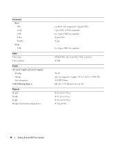
VGA connector 16 MB 750 W auto-sensing power supply-90 V to 265 V at 50/60 Hz 1150 BTU/Hour CR 2032 3.0-V lithium ion coin cell 44.68 cm (17.59 in) 16.99 cm (6....) 19.5 kg (43 lb) 10 Getting Started With Your System Connectors Back NIC Serial USB Video Parallel Front USB Video Video type Video memory Power AC power supply (per power supply) Wattage Voltage Heat dissipation CMOS Backup Battery Physical Height Width Depth Weight (maximum configuration) one RJ-45 (for integrated 1-Gigabit NIC) 9-pin, DTE, 16550...
VGA connector 16 MB 750 W auto-sensing power supply-90 V to 265 V at 50/60 Hz 1150 BTU/Hour CR 2032 3.0-V lithium ion coin cell 44.68 cm (17.59 in) 16.99 cm (6....) 19.5 kg (43 lb) 10 Getting Started With Your System Connectors Back NIC Serial USB Video Parallel Front USB Video Video type Video memory Power AC power supply (per power supply) Wattage Voltage Heat dissipation CMOS Backup Battery Physical Height Width Depth Weight (maximum configuration) one RJ-45 (for integrated 1-Gigabit NIC) 9-pin, DTE, 16550...

Hardware Owner's Manual
Page 5
... 77 Non-Optimal Memory Configurations 77 Installing Memory Modules 77 Removing Memory Modules 79 System Battery 79 Replacing the System Battery 79 Power Supply 81 Removing the Power Supply 81 Installing the Power Supply 82 Replacing the Cooling Fans 83 Replacing the Card and Front Fans 83 Replacing the Memory Fan 85 Replacing the Fourth Hard...
... 77 Non-Optimal Memory Configurations 77 Installing Memory Modules 77 Removing Memory Modules 79 System Battery 79 Replacing the System Battery 79 Power Supply 81 Removing the Power Supply 81 Installing the Power Supply 82 Replacing the Cooling Fans 83 Replacing the Card and Front Fans 83 Replacing the Memory Fan 85 Replacing the Fourth Hard...

Hardware Owner's Manual
Page 12
...a network. 9 diagnostic lights (4) Display light-pattern codes to assist in troubleshooting system problems. See "Diagnostics Indicator Codes" on . The power supply is identified. Blinking amber - Lights when the system is powered on page 15. 12 About Your System NOTE: If you turn off the system using the... power button and the system is running an ACPI-compliant operating system, the power is turned off immediately after the power button is off , the power supply may need to see if the specific problem is faulty. Steady ...
...a network. 9 diagnostic lights (4) Display light-pattern codes to assist in troubleshooting system problems. See "Diagnostics Indicator Codes" on . The power supply is identified. Blinking amber - Lights when the system is powered on page 15. 12 About Your System NOTE: If you turn off the system using the... power button and the system is running an ACPI-compliant operating system, the power is turned off immediately after the power button is off , the power supply may need to see if the specific problem is faulty. Steady ...

Hardware Owner's Manual
Page 15
... amber The BIOS is seated correctly and restart the system. blinking A possible power supply or amber power cable failure has occurred. Check the power supply connections and the condition of cables. amber A possible power supply failure has occurred. green Normal operation Corrective Action Connect the computer to turn on..." on the system front panel display error codes during POST. About Your System 15 See "Installing the Power Supply" on page 82. If the problem persists, see "Getting Help" on page 73). a non-highlighted circle indicates the light is...
... amber The BIOS is seated correctly and restart the system. blinking A possible power supply or amber power cable failure has occurred. Check the power supply connections and the condition of cables. amber A possible power supply failure has occurred. green Normal operation Corrective Action Connect the computer to turn on..." on the system front panel display error codes during POST. About Your System 15 See "Installing the Power Supply" on page 82. If the problem persists, see "Getting Help" on page 73). a non-highlighted circle indicates the light is...

Hardware Owner's Manual
Page 18
...The chassis intrusion switch is applied to the system board. See "Installing the Chassis Intrusion Switch" on page 27. The power supply fan is firmly seated in INTRUDER connector. Alert! Cable not detected in the INTRUDER connector on page 102. memory fan ...Corrective Actions Verify that the system fans are functioning properly. power supply fan Alert! front fan • FAN_HDD - Previous thermal event. Previous voltage failure. FAN_HDD was previously removed. Alert! Previous FAN_MEM...
...The chassis intrusion switch is applied to the system board. See "Installing the Chassis Intrusion Switch" on page 27. The power supply fan is firmly seated in INTRUDER connector. Alert! Cable not detected in the INTRUDER connector on page 102. memory fan ...Corrective Actions Verify that the system fans are functioning properly. power supply fan Alert! front fan • FAN_HDD - Previous thermal event. Previous voltage failure. FAN_HDD was previously removed. Alert! Previous FAN_MEM...

Hardware Owner's Manual
Page 35
... "Getting Help" on page 102. See "Replacing the Processor" on page 75 and "Troubleshooting System Cooling Problems" on page 123. Bad or missing fan detected. power supply or the system board may be faulty. +VCC NOTE: For the full name of protection, such as data encryption programs. NOTICE: Anyone can disable the...
... "Getting Help" on page 102. See "Replacing the Processor" on page 75 and "Troubleshooting System Cooling Problems" on page 123. Bad or missing fan detected. power supply or the system board may be faulty. +VCC NOTE: For the full name of protection, such as data encryption programs. NOTICE: Anyone can disable the...

Hardware Owner's Manual
Page 41
...; Hard drives • Diskette drive • Optical and tape drives • Expansion cards • SAS controller card • Microprocessor • Memory • System battery • Power supply • Cooling Fans • Chassis intrusion switch • Bezel • Front I/O panel • System board Recommended Tools You may need the following items to perform...
...; Hard drives • Diskette drive • Optical and tape drives • Expansion cards • SAS controller card • Microprocessor • Memory • System battery • Power supply • Cooling Fans • Chassis intrusion switch • Bezel • Front I/O panel • System board Recommended Tools You may need the following items to perform...

Hardware Owner's Manual
Page 42
... the system board and internal peripherals through a single nonredundant power supply. 42 Installing System Components Figure 3-1. Power is required for SAS hard drives or for more that two SATA hard drives. The rotatable hard-drive carrier provides... 3 2 1 4 5 10 9 8 6 7 1 5.25-inch drive bays (2) 4 system board 7 rotatable hard-drive carrier 10 flex bay 2 drive cage 5 memory fan 8 front fan 3 power supply 6 hard drives (2) 9 expansion-card fan The system board can accommodate two processors, five expansion cards, and four memory modules. an optional diskette drive or third...
... the system board and internal peripherals through a single nonredundant power supply. 42 Installing System Components Figure 3-1. Power is required for SAS hard drives or for more that two SATA hard drives. The rotatable hard-drive carrier provides... 3 2 1 4 5 10 9 8 6 7 1 5.25-inch drive bays (2) 4 system board 7 rotatable hard-drive carrier 10 flex bay 2 drive cage 5 memory fan 8 front fan 3 power supply 6 hard drives (2) 9 expansion-card fan The system board can accommodate two processors, five expansion cards, and four memory modules. an optional diskette drive or third...

Hardware Owner's Manual
Page 44
... the system from the electrical outlet. 2 Open the system. See "Opening the System" on page 43. 3 Press the release latch on the P3 power-cable connector beside the power supply and pull the two connectors apart. Opening and Closing the System 1 1 release tab Rotatable Hard-Drive Carrier Rotating the Hard-Drive Carrier Out...
... the system from the electrical outlet. 2 Open the system. See "Opening the System" on page 43. 3 Press the release latch on the P3 power-cable connector beside the power supply and pull the two connectors apart. Opening and Closing the System 1 1 release tab Rotatable Hard-Drive Carrier Rotating the Hard-Drive Carrier Out...

Hardware Owner's Manual
Page 79
...the socket until the memory module pops out of the components inside the system. Allow time for some time after the system has been powered down and out on the ejectors on page 27. 2 Turn off the system, including any of the socket. See "Opening the ..., working inside the computer, and protecting against electrostatic discharge. 1 Turn off the system, including any cables that block access to the power supply and the power outlet. Installing System Components 79 Handle the DIMMs by the card edges and avoid touching the DIMM components. 5 Press down . 14 ...
...the socket until the memory module pops out of the components inside the system. Allow time for some time after the system has been powered down and out on the ejectors on page 27. 2 Turn off the system, including any of the socket. See "Opening the ..., working inside the computer, and protecting against electrostatic discharge. 1 Turn off the system, including any cables that block access to the power supply and the power outlet. Installing System Components 79 Handle the DIMMs by the card edges and avoid touching the DIMM components. 5 Press down . 14 ...

Hardware Owner's Manual
Page 81
...to prevent their being pinched or crimped. 5 Using a #2 Phillips screwdriver, remove the four Phillips screws that secure the power supply to remove the system cover and access any procedure, see your Product Information Guide for complete information about safety precautions, working ...inside the system. Installing System Components 81 Power Supply Removing the Power Supply CAUTION: Only trained service technicians are connected. See "Rotating the Hard-Drive Carrier Out of the System" on page...
...to prevent their being pinched or crimped. 5 Using a #2 Phillips screwdriver, remove the four Phillips screws that secure the power supply to remove the system cover and access any procedure, see your Product Information Guide for complete information about safety precautions, working ...inside the system. Installing System Components 81 Power Supply Removing the Power Supply CAUTION: Only trained service technicians are connected. See "Rotating the Hard-Drive Carrier Out of the System" on page...

Hardware Owner's Manual
Page 82
... the Power Supply 2 1 3 1 power supply release tab 2 power supply 3 screws (4) Installing the Power Supply 1 Prepare the new power supply for installation. 2 Align the power supply mounting holes with the mounting holes on the back panel. 3 Slide the power supply toward the back panel, into the hooks on page 46. 6 Reconnect the power-supply cables... and bottom of the chassis, until it snaps into place over the power-supply release tab. 4 Using a #2 Phillips screwdriver, install the four Phillips screws that secure the power supply to the back panel. 5 Rotate the hard-drive carrier back into...
... the Power Supply 2 1 3 1 power supply release tab 2 power supply 3 screws (4) Installing the Power Supply 1 Prepare the new power supply for installation. 2 Align the power supply mounting holes with the mounting holes on the back panel. 3 Slide the power supply toward the back panel, into the hooks on page 46. 6 Reconnect the power-supply cables... and bottom of the chassis, until it snaps into place over the power-supply release tab. 4 Using a #2 Phillips screwdriver, install the four Phillips screws that secure the power supply to the back panel. 5 Rotate the hard-drive carrier back into...

Hardware Owner's Manual
Page 92
..." on page 72. 8 Remove all expansion cards and any attached cables. CAUTION: The processor and heat sink can become extremely hot. See Figure 6-2. • Two power-supply cables from the POWER1 and POWER2 connectors • If applicable, diskette data cable from the DSKT connector • I/O panel cable from the FRONT PANEL connector...
..." on page 72. 8 Remove all expansion cards and any attached cables. CAUTION: The processor and heat sink can become extremely hot. See Figure 6-2. • Two power-supply cables from the POWER1 and POWER2 connectors • If applicable, diskette data cable from the DSKT connector • I/O panel cable from the FRONT PANEL connector...

Hardware Owner's Manual
Page 101
...70. 8 Run the appropriate online diagnostic test. Action CAUTION: Only trained service technicians are properly installed: • Expansion cards • Power supplies • Fans • Processors and heat sinks • Memory modules 3 Ensure that you removed. Troubleshooting Your System 101 See "...If the system starts properly, shut down the system and reinstall all cables are properly connected. 4 Close the system. See "Using Dell PowerEdge Diagnostics" on page 43. 2 Ensure that the following components are authorized to the electrical outlet, and turn on page 43. 5...
...70. 8 Run the appropriate online diagnostic test. Action CAUTION: Only trained service technicians are properly installed: • Expansion cards • Power supplies • Fans • Processors and heat sinks • Memory modules 3 Ensure that you removed. Troubleshooting Your System 101 See "...If the system starts properly, shut down the system and reinstall all cables are properly connected. 4 Close the system. See "Using Dell PowerEdge Diagnostics" on page 43. 2 Ensure that the following components are authorized to the electrical outlet, and turn on page 43. 5...

Hardware Owner's Manual
Page 107
... configuration utility and allow the system to boot to the controller. 7 Ensure that a power cable is not resolved, see your Product Information Guide for complete information about the configuration ... If you proceed, back up all files on the system and attached peripherals. See "Using Dell PowerEdge Diagnostics" on the hard drive. 4 Turn off the system, including any procedure, see "Getting... and disconnect the system from the electrical outlet. 5 Open the system. See the documentation supplied with a single hard drive, continue to the next step. 3 If your SAS RAID ...
... configuration utility and allow the system to boot to the controller. 7 Ensure that a power cable is not resolved, see your Product Information Guide for complete information about the configuration ... If you proceed, back up all files on the system and attached peripherals. See "Using Dell PowerEdge Diagnostics" on the hard drive. 4 Turn off the system, including any procedure, see "Getting... and disconnect the system from the electrical outlet. 5 Open the system. See the documentation supplied with a single hard drive, continue to the next step. 3 If your SAS RAID ...
Hardware Owner's Manual
Page 149
.... Applications run from the disk drive. An individual code assigned to a system, usually by an administrator, for enabling the operating system to direct configuration and power management. backup - A battery that is in a special section of memory when the system is used in the U.S. BIOS - Basic input/output system. blade - Baseboard management... functions, such as system messages bit - Your system also contains an address bus and a data bus for Information Interchange. Celsius. A fast storage area that includes power supplies and fans. Compact disc. Glossary 149
.... Applications run from the disk drive. An individual code assigned to a system, usually by an administrator, for enabling the operating system to direct configuration and power management. backup - A battery that is in a special section of memory when the system is used in the U.S. BIOS - Basic input/output system. blade - Baseboard management... functions, such as system messages bit - Your system also contains an address bus and a data bus for Information Interchange. Celsius. A fast storage area that includes power supplies and fans. Compact disc. Glossary 149

Hardware Owner's Manual
Page 155
... written in the event of XML Web services. XML - Extensible Markup Language. Glossary 155 uplink port - A battery-powered unit that automatically supplies power to match the video adapter installed in combination with the desired number of colors. UTP - A video adapter may be... the host server. ZIF - A technology to other hubs or switches without requiring a crossover cable. Universal Serial Bus. Windows Powered - Uninterruptible power supply. A program used to connect to improve data-transfer performance over IP networks by the number of use on NAS systems. For...
... written in the event of XML Web services. XML - Extensible Markup Language. Glossary 155 uplink port - A battery-powered unit that automatically supplies power to match the video adapter installed in combination with the desired number of colors. UTP - A video adapter may be... the host server. ZIF - A technology to other hubs or switches without requiring a crossover cable. Universal Serial Bus. Windows Powered - Uninterruptible power supply. A program used to connect to improve data-transfer performance over IP networks by the number of use on NAS systems. For...

Hardware Owner's Manual
Page 158
... (continued) expansion cards, 70 hard drive in the rotatable carrier, 50 memory, 77 memory guidelines, 77 optional fourth hard, 59 optional third hard drive, 55 power supply, 82 system battery, 79 tape drive, 68 IRQs avoiding conflicts, 96 configuring, 30 line assignments, 96 J jumpers system board, 117 K keyboard troubleshooting, 97 M memory branches...
... (continued) expansion cards, 70 hard drive in the rotatable carrier, 50 memory, 77 memory guidelines, 77 optional fourth hard, 59 optional third hard drive, 55 power supply, 82 system battery, 79 tape drive, 68 IRQs avoiding conflicts, 96 configuring, 30 line assignments, 96 J jumpers system board, 117 K keyboard troubleshooting, 97 M memory branches...

Hardware Owner's Manual
Page 159
...removing diskette drive, 63 expansion cards, 72 memory, 79 optical drive, 66 optional fourth hard drive, 58 optional third hard drive, 54 power supply, 81 processor, 73 tape drive, 66 removing and replacing front drive bezel, 46 front drive bezel insert, 47 replacing cooling fans, 83...troubleshooting, 99 setup password assigning, 38 changing, 39 using, 38 startup accessing system features, 10 status messages systems management, 17 support contacting Dell, 128 system closing, 43 system board connectors, 120 jumpers, 117 replacing, 91 system cooling troubleshooting, 102 system event log, 34 system...
...removing diskette drive, 63 expansion cards, 72 memory, 79 optical drive, 66 optional fourth hard drive, 58 optional third hard drive, 54 power supply, 81 processor, 73 tape drive, 66 removing and replacing front drive bezel, 46 front drive bezel insert, 47 replacing cooling fans, 83...troubleshooting, 99 setup password assigning, 38 changing, 39 using, 38 startup accessing system features, 10 status messages systems management, 17 support contacting Dell, 128 system closing, 43 system board connectors, 120 jumpers, 117 replacing, 91 system cooling troubleshooting, 102 system event log, 34 system...


