User Manual
Page 7
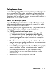
... any components in this document or as to be components in a rack, install all front and side stabilizers. Failure to install stabilizers can be included in the rack. The rack can allow the rack to tip over. • Always load from potential damage. CAUTION: Instructions for Rack-Mounted Systems: • Your rack kit has been approved only for trained service technicians installing a rack enclosure. Dell disclaims all applicable...
... any components in this document or as to be components in a rack, install all front and side stabilizers. Failure to install stabilizers can be included in the rack. The rack can allow the rack to tip over. • Always load from potential damage. CAUTION: Instructions for Rack-Mounted Systems: • Your rack kit has been approved only for trained service technicians installing a rack enclosure. Dell disclaims all applicable...
Dell PowerEdge 2420 Rack Installation Guide
Page 7
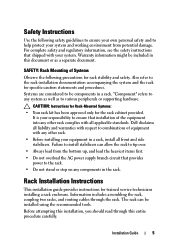
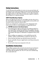
... document. "Component" refers to install stabilizers can be components in the rack. Failure to any components in a rack. Installation Guide 5 For complete safety and regulatory information, see the safety instructions that shipped with all applicable standards. Also refer to various peripherals or supporting hardware. Dell disclaims all front and side stabilizers. Information includes assembling the rack and routing cables through the rack. The 24-U rack...
... document. "Component" refers to install stabilizers can be components in the rack. Failure to any components in a rack. Installation Guide 5 For complete safety and regulatory information, see the safety instructions that shipped with all applicable standards. Also refer to various peripherals or supporting hardware. Dell disclaims all front and side stabilizers. Information includes assembling the rack and routing cables through the rack. The 24-U rack...
User Manual
Page 9
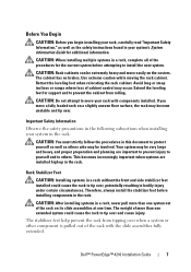
... could cause the rack to protect yourself as well as the safety instructions found in the rack. Use extreme caution while moving the rack cabinet. If you begin installing your system in a rack, complete all of the procedures for additional information. Avoid long or steep inclines or ramps where loss of the rack with components installed. The weight of more...
... could cause the rack to protect yourself as well as the safety instructions found in the rack. Use extreme caution while moving the rack cabinet. If you begin installing your system in a rack, complete all of the procedures for additional information. Avoid long or steep inclines or ramps where loss of the rack with components installed. The weight of more...
Cabling PowerEdge R815
Page 4
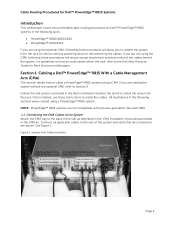
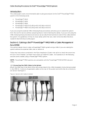
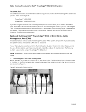
... without powering down or disconnecting the cables. If you are secure. Connect all applicable cables to the rear of the rails as described in the CMA Installation Instructions provided in the CMA kit. All illustrations in the rail kit to install the cables. Section 1: Cabling a Dell™ PowerEdge™ R815 With a Cable Management Arm (CMA) This section details how to the Dell Best Practices Guide for Rack Enclosure white paper. NOTE: PowerEdge™...
... without powering down or disconnecting the cables. If you are secure. Connect all applicable cables to the rear of the rails as described in the CMA Installation Instructions provided in the CMA kit. All illustrations in the rail kit to install the cables. Section 1: Cabling a Dell™ PowerEdge™ R815 With a Cable Management Arm (CMA) This section details how to the Dell Best Practices Guide for Rack Enclosure white paper. NOTE: PowerEdge™...
Cabling PowerEdge R810
Page 4
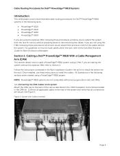
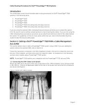
... the Rack Installation Guide in the rail kit to the Dell Best Practices Guide for Rack Enclosure white paper. Connect all applicable cables to install the cables. Figure 1: System with previous generation rails and CMAs. 1.1 Connecting the CMA Cables to the System Attach the CMA tray to the back of the system and verify that all connections are using the CMA, following these instructions to the rear of the rails as...
... the Rack Installation Guide in the rail kit to the Dell Best Practices Guide for Rack Enclosure white paper. Connect all applicable cables to install the cables. Figure 1: System with previous generation rails and CMAs. 1.1 Connecting the CMA Cables to the System Attach the CMA tray to the back of the system and verify that all connections are using the CMA, following these instructions to the rear of the rails as...
Cabling PowerEdge R715
Page 4
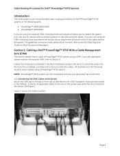
... rails as described in the CMA Installation Instructions provided in the CMA kit. If you are not using the CMA, following these procedures will allow you to cable a PowerEdge™ R715 system using a CMA. Section 1: Cabling a Dell™ PowerEdge™ R715 With a Cable Management Arm (CMA) This section details how to extend the system from the rack for Rack Enclosure white paper. Cable Routing Procedures for Dell™ PowerEdge...
... rails as described in the CMA Installation Instructions provided in the CMA kit. If you are not using the CMA, following these procedures will allow you to cable a PowerEdge™ R715 system using a CMA. Section 1: Cabling a Dell™ PowerEdge™ R715 With a Cable Management Arm (CMA) This section details how to extend the system from the rack for Rack Enclosure white paper. Cable Routing Procedures for Dell™ PowerEdge...
Cabling PowerEdge R710
Page 8
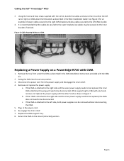
... the left CMA bracket. 3. Remove the tray from the power supply and disengage the strain relief. 4. Plug in the CMA Installation Instructions provided with the rail kit, bundle the cables and secure them to be disconnected. Return the CMA to the left rail or right rail CMA attachment brackets as shown in the Rack Installation Guide. Disconnect the power cord from under the CMA...
... the left CMA bracket. 3. Remove the tray from the power supply and disengage the strain relief. 4. Plug in the CMA Installation Instructions provided with the rail kit, bundle the cables and secure them to be disconnected. Return the CMA to the left rail or right rail CMA attachment brackets as shown in the Rack Installation Guide. Disconnect the power cord from under the CMA...
Cabling PowerEdge R610
Page 9
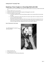
... not need to be disconnected. Figure 9: Replacing Outer Power Supply Inner CMA attachment housing has been disconnected 5. Plug in Figure 9. Remove the tray from the power supply and disengage the strain relief. 4. While supporting the CMA with one hand, remove and replace the power supply with the other hand as described in the CMA Installation Instructions provided with CMA 1. Re‐engage the...
... not need to be disconnected. Figure 9: Replacing Outer Power Supply Inner CMA attachment housing has been disconnected 5. Plug in Figure 9. Remove the tray from the power supply and disengage the strain relief. 4. While supporting the CMA with one hand, remove and replace the power supply with the other hand as described in the CMA Installation Instructions provided with CMA 1. Re‐engage the...
Best Practices Guide for Rack Enclosures
Page 4
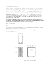
... some best practices when installing and using a Dell 2420 or 4220 Rack Enclosure. The 2420 Rack Enclosure is a 24U rack that is solidly built and delivered with Dell quality service, support, and reliability. Dell PowerEdge servers fit into these racks as a guide to hold and protect server, network, and data storage equipment. This document is a sturdy, practical design that has the following dimensions shown in any environment: a data center, a remote office, a wiring closet, or...
... some best practices when installing and using a Dell 2420 or 4220 Rack Enclosure. The 2420 Rack Enclosure is a 24U rack that is solidly built and delivered with Dell quality service, support, and reliability. Dell PowerEdge servers fit into these racks as a guide to hold and protect server, network, and data storage equipment. This document is a sturdy, practical design that has the following dimensions shown in any environment: a data center, a remote office, a wiring closet, or...
Best Practices Guide for Rack Enclosures
Page 14
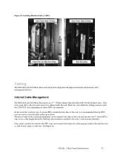
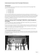
... trays be used to route all cables either the cable rings provided in the sides of the rack and into the zero-U mount PDUs. Any excess cable length should be routed to the PDU trays and secured with improved internal and external cable management features. Internal Cable Management The Dell 2420 and 4220 Rack Enclosures are mounted. Data cables can be routed to the rack's vertical frame members. Dell Inc. | Data Center...
... trays be used to route all cables either the cable rings provided in the sides of the rack and into the zero-U mount PDUs. Any excess cable length should be routed to the PDU trays and secured with improved internal and external cable management features. Internal Cable Management The Dell 2420 and 4220 Rack Enclosures are mounted. Data cables can be routed to the rack's vertical frame members. Dell Inc. | Data Center...
Cabling PowerEdge T710
Page 4
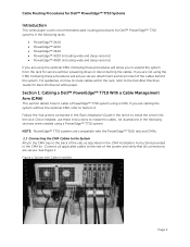
... all connections are compatible with Cables Installed Page 2 Once installed, use these procedures will allow you are not using the CMA, following sections were created using a CMA. If you are cabling the system without powering down or disconnecting the cables. Section 1: Cabling a Dell™ PowerEdge™ T710 With a Cable Management Arm (CMA) This section details how to install the server into the rack. All illustrations in the rail kit to cable a PowerEdge...
... all connections are compatible with Cables Installed Page 2 Once installed, use these procedures will allow you are not using the CMA, following sections were created using a CMA. If you are cabling the system without powering down or disconnecting the cables. Section 1: Cabling a Dell™ PowerEdge™ T710 With a Cable Management Arm (CMA) This section details how to install the server into the rack. All illustrations in the rail kit to cable a PowerEdge...
Cabling PowerEdge T710
Page 8
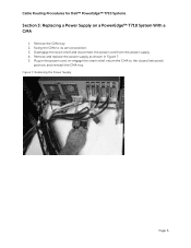
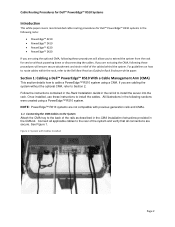
Disengage the strain relief and disconnect the power cord from the power supply. 4. Cable Routing Procedures for Dell™ PowerEdge™ T710 Systems Section 3: Replacing a Power Supply on a PowerEdge™ T710 System With a CMA 1. Figure 7: Replacing the Power Supply Page 6 Swing the CMA to the closed (retracted) position, and reinstall the CMA tray. Remove and replace the power supply as shown in the power cord, re-engage the strain relief, return the CMA to its service position. 3. Remove the CMA tray. 2. Plug in Figure 7. 5.
Disengage the strain relief and disconnect the power cord from the power supply. 4. Cable Routing Procedures for Dell™ PowerEdge™ T710 Systems Section 3: Replacing a Power Supply on a PowerEdge™ T710 System With a CMA 1. Figure 7: Replacing the Power Supply Page 6 Swing the CMA to the closed (retracted) position, and reinstall the CMA tray. Remove and replace the power supply as shown in the power cord, re-engage the strain relief, return the CMA to its service position. 3. Remove the CMA tray. 2. Plug in Figure 7. 5.
Cabling PowerEdge T610
Page 4
... rear of the rails as described in the CMA Installation Instructions provided in the following these instructions to install the server into the rack. Section 1: Cabling a Dell™ PowerEdge™ T610 With a Cable Management Arm (CMA) This section details how to cable a PowerEdge™ T610 system using the optional CMA, following racks: PowerEdge™ 2410 PowerEdge™ 4210 PowerEdge™ 2420 PowerEdge™ 4220 (including wide and deep versions...
... rear of the rails as described in the CMA Installation Instructions provided in the following these instructions to install the server into the rack. Section 1: Cabling a Dell™ PowerEdge™ T610 With a Cable Management Arm (CMA) This section details how to cable a PowerEdge™ T610 system using the optional CMA, following racks: PowerEdge™ 2410 PowerEdge™ 4210 PowerEdge™ 2420 PowerEdge™ 4220 (including wide and deep versions...
Cabling PowerEdge R515
Page 4
... Guide for service without the optional CMA, refer to install the cables. See Figure 1. Follow the instructions contained in the Rack Installation Guide in the rail kit to cable a PowerEdge™ R515 system using a CMA. Section 1: Cabling a Dell™ PowerEdge™ R515 With a Cable Management Arm (CMA) This section details how to install the server into the rack. Once installed, use these procedures will allow you to extend the system from the rack for Rack Enclosure...
... Guide for service without the optional CMA, refer to install the cables. See Figure 1. Follow the instructions contained in the Rack Installation Guide in the rail kit to cable a PowerEdge™ R515 system using a CMA. Section 1: Cabling a Dell™ PowerEdge™ R515 With a Cable Management Arm (CMA) This section details how to install the server into the rack. Once installed, use these procedures will allow you to extend the system from the rack for Rack Enclosure...
Cabling PowerEdge R510
Page 4
... cables. See Figure 1. Section 1: Cabling a Dell™ PowerEdge™ R510 With a Cable Management Arm (CMA) This section details how to install the server into the rack. Follow the instructions contained in the Rack Installation Guide in the rail kit to cable a PowerEdge™ R510 system using a CMA. Connect all connections are secure. NOTE: PowerEdge™ R510 systems are not compatible with Cables Installed Page 2 Once installed, use these instructions to extend the system from the rack for service...
... cables. See Figure 1. Section 1: Cabling a Dell™ PowerEdge™ R510 With a Cable Management Arm (CMA) This section details how to install the server into the rack. Follow the instructions contained in the Rack Installation Guide in the rail kit to cable a PowerEdge™ R510 system using a CMA. Connect all connections are secure. NOTE: PowerEdge™ R510 systems are not compatible with Cables Installed Page 2 Once installed, use these instructions to extend the system from the rack for service...
Cabling PowerEdge R415
Page 4
... service without the optional CMA, refer to the back of the rails as described in the CMA Installation Instructions provided in the CMA kit. See Figure 1. Section 1: Cabling a Dell™ PowerEdge™ R415 With a Cable Management Arm (CMA) This section details how to the Dell Best Practices Guide for Rack Enclosure white paper. Once installed, use these instructions to install the server into the rack. Follow the instructions contained in the Rack Installation Guide...
... service without the optional CMA, refer to the back of the rails as described in the CMA Installation Instructions provided in the CMA kit. See Figure 1. Section 1: Cabling a Dell™ PowerEdge™ R415 With a Cable Management Arm (CMA) This section details how to the Dell Best Practices Guide for Rack Enclosure white paper. Once installed, use these instructions to install the server into the rack. Follow the instructions contained in the Rack Installation Guide...
Cabling PowerEdge R410
Page 4
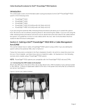
... the cables. Follow the instructions contained in the Rack Installation Guide in the CMA kit. NOTE: PowerEdge™ R310 & R410 systems are not compatible with Cables Installed Page 2 Figure 1: System with previous generation rails and CMAs. 1.1 Connecting the CMA Cables to the System Attach the CMA tray to the back of the cables behind the system. Section 1: Cabling a Dell™ PowerEdge™ R310 or R410 With a Cable Management...
... the cables. Follow the instructions contained in the Rack Installation Guide in the CMA kit. NOTE: PowerEdge™ R310 & R410 systems are not compatible with Cables Installed Page 2 Figure 1: System with previous generation rails and CMAs. 1.1 Connecting the CMA Cables to the System Attach the CMA tray to the back of the cables behind the system. Section 1: Cabling a Dell™ PowerEdge™ R310 or R410 With a Cable Management...
Cabling PowerEdge R910
Page 4
... kit. Figure 1: System with previous generation rails and CMAs. 1.1 Connecting the CMA Cables to the System Attach the CMA tray to the back of the cables behind the system. For guidelines on how to route cables within the rack, refer to the Dell Best Practices Guide for Rack Enclosure white paper. If you are using the optional CMA, following these instructions to install the server...
... kit. Figure 1: System with previous generation rails and CMAs. 1.1 Connecting the CMA Cables to the System Attach the CMA tray to the back of the cables behind the system. For guidelines on how to route cables within the rack, refer to the Dell Best Practices Guide for Rack Enclosure white paper. If you are using the optional CMA, following these instructions to install the server...
User Manual
Page 5
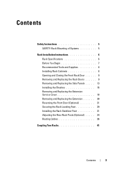
... Instructions 5 SAFETY: Rack Mounting of Systems 5 Rack Installation Instructions 6 Rack Specifications 6 Before You Begin 7 Recommended Tools and Supplies 8 Installing Rack Cabinets 8 Opening and Closing the Front Rack Door 9 Removing and Replacing the Rack Doors 9 Removing and Replacing the Side Panels . . . . . 13 Installing the Brushes 16 Removing and Replacing the Extension Service Cover 18 Removing and Replacing the Extension 20 Reversing the Front Door (Optional 21 Securing the Rack Leveling Feet 29 Installing the Rack Stabilizer Feet 31 Adjusting the Rear Rack Posts...
... Instructions 5 SAFETY: Rack Mounting of Systems 5 Rack Installation Instructions 6 Rack Specifications 6 Before You Begin 7 Recommended Tools and Supplies 8 Installing Rack Cabinets 8 Opening and Closing the Front Rack Door 9 Removing and Replacing the Rack Doors 9 Removing and Replacing the Side Panels . . . . . 13 Installing the Brushes 16 Removing and Replacing the Extension Service Cover 18 Removing and Replacing the Extension 20 Reversing the Front Door (Optional 21 Securing the Rack Leveling Feet 29 Installing the Rack Stabilizer Feet 31 Adjusting the Rear Rack Posts...
User Manual
Page 7
... peripherals or supporting hardware. CAUTION: Instructions for Rack-Mounted Systems: • Your rack kit has been approved only for rack stability and safety. Installation Guide 5 Warranty information may be included in this document or as to any components in the enclosure. • Before installing your responsibility to ensure that provides power to protect your equipment. For complete safety and regulatory information, see the rack installation documentation accompanying...
... peripherals or supporting hardware. CAUTION: Instructions for Rack-Mounted Systems: • Your rack kit has been approved only for rack stability and safety. Installation Guide 5 Warranty information may be included in this document or as to any components in the enclosure. • Before installing your responsibility to ensure that provides power to protect your equipment. For complete safety and regulatory information, see the rack installation documentation accompanying...


