
Hardware Owner's Manual
Page 13
... panel LCD menu. Provides system ID, status information, and system error messages. Use this button only if directed to do so by qualified support personnel or by descriptive text. The LCD lights amber when the system needs attention, and the LCD panel displays an error code followed by ... buttons 7 LCD panel Description Used to troubleshoot software and device driver errors when using certain operating systems. This button can be pressed using the end of whether the system has been powered on. Allows you to the system. The ports are USB 2.0-compliant. A slide-out panel for an...
... panel LCD menu. Provides system ID, status information, and system error messages. Use this button only if directed to do so by qualified support personnel or by descriptive text. The LCD lights amber when the system needs attention, and the LCD panel displays an error code followed by ... buttons 7 LCD panel Description Used to troubleshoot software and device driver errors when using certain operating systems. This button can be pressed using the end of whether the system has been powered on. Allows you to the system. The ports are USB 2.0-compliant. A slide-out panel for an...
Hardware Owner's Manual
Page 91
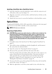
...: Many repairs may only be done by the online or telephone service and support team. You should only perform troubleshooting and simple repairs as authorized in your ... only. See Figure 3-7. 6 Slide the optical drive out of the system until it is not covered by Dell is free of the drive. See "Opening the System" on the system as directed by a certified service technician...Drive An optional DVD-ROM or DVD+/-RW optical drive slides into the hard-drive carrier with the connector end of "Sliding the Front-Chassis Assembly" on page 83. 2 Turn off the system, including any attached ...
...: Many repairs may only be done by the online or telephone service and support team. You should only perform troubleshooting and simple repairs as authorized in your ... only. See Figure 3-7. 6 Slide the optical drive out of the system until it is not covered by Dell is free of the drive. See "Opening the System" on the system as directed by a certified service technician...Drive An optional DVD-ROM or DVD+/-RW optical drive slides into the hard-drive carrier with the connector end of "Sliding the Front-Chassis Assembly" on page 83. 2 Turn off the system, including any attached ...

Hardware Owner's Manual
Page 105
...plan to touch for future use. Read and follow the safety instructions that is not authorized by Dell is not covered by the card edges and avoid touching the components on page 84. 4 ... Shroud" on each memory module only on page 83. 3 Open the system. CAUTION: Handle each end of the socket until the memory-module blank pops out of the memory module. NOTE: Make sure ... sockets in your warranty. CAUTION: Many repairs may only be done by the online or telephone service and support team. See Figure 3-11. 7 If applicable, remove the memory-module blanks from the electrical outlet. ...
...plan to touch for future use. Read and follow the safety instructions that is not authorized by Dell is not covered by the card edges and avoid touching the components on page 84. 4 ... Shroud" on each memory module only on page 83. 3 Open the system. CAUTION: Handle each end of the socket until the memory-module blank pops out of the memory module. NOTE: Make sure ... sockets in your warranty. CAUTION: Many repairs may only be done by the online or telephone service and support team. See Figure 3-11. 7 If applicable, remove the memory-module blanks from the electrical outlet. ...

Hardware Owner's Manual
Page 128
...Storage Controller Card CAUTION: Many repairs may only be done by the online or telephone service and support team. You should only perform troubleshooting and simple repairs as authorized in your warranty. See Figure 3-... the back corner of the system. 2 With the label side facing up, insert the contact-pin end of the SD card into the optional iDRAC6 Enterprise card at the back corner of the chassis. 6... to the SAS data cable connector on the backplane. NOTE: Ensure that is not authorized by Dell is fully seated. 4 Connect the SAS data cable to the connector labels on the module....
...Storage Controller Card CAUTION: Many repairs may only be done by the online or telephone service and support team. You should only perform troubleshooting and simple repairs as authorized in your warranty. See Figure 3-... the back corner of the system. 2 With the label side facing up, insert the contact-pin end of the SD card into the optional iDRAC6 Enterprise card at the back corner of the chassis. 6... to the SAS data cable connector on the backplane. NOTE: Ensure that is not authorized by Dell is fully seated. 4 Connect the SAS data cable to the connector labels on the module....


