Setting Up EMC PowerEdge Server Using Lifecycle Controller
Page 3
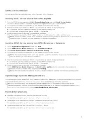
..., the Service Module installer file is complete, iDRAC displays the Service Module as Running. From the iDRAC Settings page, select iDRAC Service Module Setup page, click Install Service Module. iDRAC Service Module You can install iDRAC Service Module using: iDRAC Express or iDRAC Enterprise. NOTE: The Service Module installer will be available to https://www.dell.com/openmanagemanuals. 3 Click Launch Virtual Console > Continue on the Systems Management Tools and Documentation DVD (optional). Related Dell products ● Integrated Dell Remote Access Controller With Lifecycle...
..., the Service Module installer file is complete, iDRAC displays the Service Module as Running. From the iDRAC Settings page, select iDRAC Service Module Setup page, click Install Service Module. iDRAC Service Module You can install iDRAC Service Module using: iDRAC Express or iDRAC Enterprise. NOTE: The Service Module installer will be available to https://www.dell.com/openmanagemanuals. 3 Click Launch Virtual Console > Continue on the Systems Management Tools and Documentation DVD (optional). Related Dell products ● Integrated Dell Remote Access Controller With Lifecycle...

EMC Installation and Service Manual
Page 3
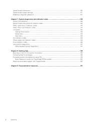
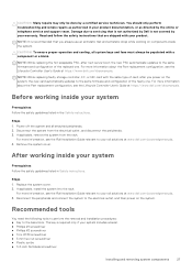
... Rail sizing and rack compatibility matrix...18 Locating the Express Service Code and Service Tag 19 Chapter 3: Initial system setup and configuration 20 Setting up the system...20 iDRAC configuration...20 Options to set up iDRAC IP address...20 Options to log in to iDRAC...21 Resources to install operating system...22 Options to download firmware ...22 Options to download and install OS drivers ...23 Downloading drivers and firmware...23 Chapter 4: Minimum to POST...
... Rail sizing and rack compatibility matrix...18 Locating the Express Service Code and Service Tag 19 Chapter 3: Initial system setup and configuration 20 Setting up the system...20 iDRAC configuration...20 Options to set up iDRAC IP address...20 Options to log in to iDRAC...21 Resources to install operating system...22 Options to download firmware ...22 Options to download and install OS drivers ...23 Downloading drivers and firmware...23 Chapter 4: Minimum to POST...
EMC Installation and Service Manual
Page 6
... codes...141 iDRAC Direct LED indicator codes...141 LCD panel...142 Viewing Home screen...143 Setup menu...143 View menu...143 NIC indicator codes...144 Power supply unit indicator codes...144 Drive indicator codes...146 Using system diagnostics...147 Dell Embedded System Diagnostics...147 Chapter 8: Getting help...149 Recycling or End-of-Life service information...149 Contacting Dell Technologies...149 Accessing system information by using QRL...149 Quick Resource Locator for PowerEdge R750xs system 150 Receiving automated support...
... codes...141 iDRAC Direct LED indicator codes...141 LCD panel...142 Viewing Home screen...143 Setup menu...143 View menu...143 NIC indicator codes...144 Power supply unit indicator codes...144 Drive indicator codes...146 Using system diagnostics...147 Dell Embedded System Diagnostics...147 Chapter 8: Getting help...149 Recycling or End-of-Life service information...149 Contacting Dell Technologies...149 Accessing system information by using QRL...149 Quick Resource Locator for PowerEdge R750xs system 150 Receiving automated support...

EMC Installation and Service Manual
Page 20
Install the system into the rack. For information about setting up iDRAC IP address Interface iDRAC Settings utility Documentation links Integrated Dell Remote Access Controller User's Guide at www.dell.com/poweredgemanuals. 3. iDRAC configuration The Integrated Dell Remote Access Controller (iDRAC) is designed to make you to perform remote management, and reduces the need for physical access to the system. iDRAC alerts you to set up iDRAC IP address, see the Dell EMC PowerEdge R750xs BIOS and UEFI Reference Guide on the system...
Install the system into the rack. For information about setting up iDRAC IP address Interface iDRAC Settings utility Documentation links Integrated Dell Remote Access Controller User's Guide at www.dell.com/poweredgemanuals. 3. iDRAC configuration The Integrated Dell Remote Access Controller (iDRAC) is designed to make you to perform remote management, and reduces the need for physical access to the system. iDRAC alerts you to set up iDRAC IP address, see the Dell EMC PowerEdge R750xs BIOS and UEFI Reference Guide on the system...

EMC Installation and Service Manual
Page 21
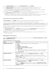
... default password available on back of your system > Documentation. Integrated Dell Remote Access Controller User's Guide at https://www.dell.com/ idracmanuals or for system specific Integrated Dell Remote Access Controller User's Guide, go to the iDRAC dedicated network port or use the iDRAC Direct port by using the USB cable. You can log in by using your platform and for latest documentation version, see KB article https://www.dell.com/support/article/ sln308699. Table 6. Lifecycle Controller Lifecycle Controller User's Guide at https://www.dell...
... default password available on back of your system > Documentation. Integrated Dell Remote Access Controller User's Guide at https://www.dell.com/ idracmanuals or for system specific Integrated Dell Remote Access Controller User's Guide, go to the iDRAC dedicated network port or use the iDRAC Direct port by using the USB cable. You can log in by using your platform and for latest documentation version, see KB article https://www.dell.com/support/article/ sln308699. Table 6. Lifecycle Controller Lifecycle Controller User's Guide at https://www.dell...
EMC Installation and Service Manual
Page 23
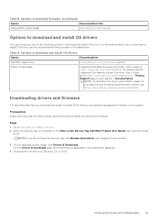
... options to the system are displayed. 4. Download the drivers to download and install OS drivers Option Dell EMC support site iDRAC virtual media Documentation Downloading drivers and firmware section. Table 8. Integrated Dell Remote Access Controller User's Guide at https://www.dell.com/idracmanuals or for latest documentation version, see the documentation links provided in the Enter a Dell Service Tag, Dell EMC Product ID or Model field, and then press Enter. Steps 1. Initial system setup and configuration 23 Prerequisites Ensure that...
... options to the system are displayed. 4. Download the drivers to download and install OS drivers Option Dell EMC support site iDRAC virtual media Documentation Downloading drivers and firmware section. Table 8. Integrated Dell Remote Access Controller User's Guide at https://www.dell.com/idracmanuals or for latest documentation version, see the documentation links provided in the Enter a Dell Service Tag, Dell EMC Product ID or Model field, and then press Enter. Steps 1. Initial system setup and configuration 23 Prerequisites Ensure that...
EMC Installation and Service Manual
Page 27
... Controller User's Guide at https://www.dell.com/idracmanuals. the new card automatically updates to the same firmware and configuration of card, after next server boot; If applicable, install the system into the rack. NOTE: While replacing faulty storage controller, FC, or NIC card with your system Prerequisites Follow the safety guidelines listed in Safety instructions. Power off the system and all system bays and fans must always be done by your rail...
... Controller User's Guide at https://www.dell.com/idracmanuals. the new card automatically updates to the same firmware and configuration of card, after next server boot; If applicable, install the system into the rack. NOTE: While replacing faulty storage controller, FC, or NIC card with your system Prerequisites Follow the safety guidelines listed in Safety instructions. Power off the system and all system bays and fans must always be done by your rail...
EMC Installation and Service Manual
Page 120
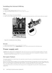
... hot spare feature that the system detects the USB memory key. the new PSU automatically updates to an active output state. If having one . While booting, press F2 to enter System Setup and verify that significantly reduces the power overhead associated with the connector on the system board and press firmly until the internal USB card is more information about the Part replacement configuration, see the Lifecycle Controller User's Guide...
... hot spare feature that the system detects the USB memory key. the new PSU automatically updates to an active output state. If having one . While booting, press F2 to enter System Setup and verify that significantly reduces the power overhead associated with the connector on the system board and press firmly until the internal USB card is more information about the Part replacement configuration, see the Lifecycle Controller User's Guide...
EMC Installation and Service Manual
Page 128
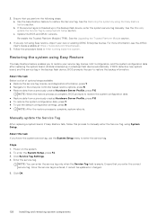
... the backup flash device, BIOS prompts the user to restore the system configuration data. ● Restore data from a previously created Hardware Server Profile, press F10 ● To restore the system configuration data, press Y ● To use the System Setup menu to restore your new or existing iDRAC Enterprise license. Follow the procedure listed in the backup flash device, enter the system service tag manually. Click Service Tag Settings. 4. Once the service tag...
... the backup flash device, BIOS prompts the user to restore the system configuration data. ● Restore data from a previously created Hardware Server Profile, press F10 ● To restore the system configuration data, press Y ● To use the System Setup menu to restore your new or existing iDRAC Enterprise license. Follow the procedure listed in the backup flash device, enter the system service tag manually. Click Service Tag Settings. 4. Once the service tag...

EMC Installation and Service Manual
Page 130
..., remove the drive backplane cover. 5. Remove the cooling fan cage assembly. Disconnect the control panel cable from the system. 2. Hold the left control panel assembly and remove the control panel along with Preboot Measurements. 4. Initialize the TPM. The TPM Status changes to enter System Setup. 2. Save the settings. 5. Control panel This is a service technician replaceable part only. Remove the air shroud. 4. Using the Phillips #1 screwdriver, remove the screws that secure the left control panel Prerequisites 1. Initializing TPM for users...
..., remove the drive backplane cover. 5. Remove the cooling fan cage assembly. Disconnect the control panel cable from the system. 2. Hold the left control panel assembly and remove the control panel along with Preboot Measurements. 4. Initialize the TPM. The TPM Status changes to enter System Setup. 2. Save the settings. 5. Control panel This is a service technician replaceable part only. Remove the air shroud. 4. Using the Phillips #1 screwdriver, remove the screws that secure the left control panel Prerequisites 1. Initializing TPM for users...
EMC Installation and Service Manual
Page 135
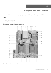
Topics: • System board connectors • System board jumper settings • Disabling a forgotten password System board connectors Figure 133. System board jumpers and connectors Jumpers and connectors 135 6 Jumpers and connectors This section provides essential and specific information about jumpers and switches. It also describes the connectors on the system board. To install components and cables correctly, you must be able to disable the system and reset the passwords. Jumpers on the system board help to identify the connectors on the various boards in the system.
Topics: • System board connectors • System board jumper settings • Disabling a forgotten password System board connectors Figure 133. System board jumpers and connectors Jumpers and connectors 135 6 Jumpers and connectors This section provides essential and specific information about jumpers and switches. It also describes the connectors on the system board. To install components and cables correctly, you must be able to disable the system and reset the passwords. Jumpers on the system board help to identify the connectors on the various boards in the system.

EMC Installation and Service Manual
Page 150
... specific product or 2. This information is an optional Dell EMC Services offering that automates technical support for your device. Use your smart phone or tablet to Dell EMC. By installing and setting up a SupportAssist application in the Quick Resource Locator section. The available benefits vary depending on your system or in your Dell EMC server, storage, and networking devices. Quick Resource Locator for PowerEdge R750xs system Receiving automated support with Dell EMC Technical Support...
... specific product or 2. This information is an optional Dell EMC Services offering that automates technical support for your device. Use your smart phone or tablet to Dell EMC. By installing and setting up a SupportAssist application in the Quick Resource Locator section. The available benefits vary depending on your system or in your Dell EMC server, storage, and networking devices. Quick Resource Locator for PowerEdge R750xs system Receiving automated support with Dell EMC Technical Support...

EMC Technical Specifications
Page 9
... Slot 6 N/A Processor 2 Low Profile Half Length Slot width x16 x8 (x4-Link) x16 x16 x16 x16 (x8-Link) x16 x16 NOTE: Only one cable riser can be installed at a time for any given configuration. Expansion card slots supported on the system configuration. Expansion card riser specifications The PowerEdge R750xs system supports up to six PCI express (PCIe) Gen 4 expansion cards. For more information about the supported fan configuration or matrix, see Thermal restriction matrix. System battery specifications The PowerEdge R750xs...
... Slot 6 N/A Processor 2 Low Profile Half Length Slot width x16 x8 (x4-Link) x16 x16 x16 x16 (x8-Link) x16 x16 NOTE: Only one cable riser can be installed at a time for any given configuration. Expansion card slots supported on the system configuration. Expansion card riser specifications The PowerEdge R750xs system supports up to six PCI express (PCIe) Gen 4 expansion cards. For more information about the supported fan configuration or matrix, see Thermal restriction matrix. System battery specifications The PowerEdge R750xs...
EMC BIOS and UEFI Reference Guide
Page 5
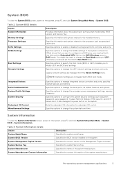
... Information Memory Settings Processor Settings SATA Settings NVMe Settings Boot Settings Network Settings Description Provides information about the system such as system password, setup password, Trusted Platform Module (TPM) security, and UEFI secure boot. Specifies information and options related to the processor such as speed and cache size. NOTE: Network Settings are managed from the Device Settings menu. Specifies options to RAID mode. System Information To view the System Information screen, power on the system. System BIOS Version Specifies the BIOS version installed...
... Information Memory Settings Processor Settings SATA Settings NVMe Settings Boot Settings Network Settings Description Provides information about the system such as system password, setup password, Trusted Platform Module (TPM) security, and UEFI secure boot. Specifies information and options related to the processor such as speed and cache size. NOTE: Network Settings are managed from the Device Settings menu. Specifies options to RAID mode. System Information To view the System Information screen, power on the system. System BIOS Version Specifies the BIOS version installed...

EMC BIOS and UEFI Reference Guide
Page 9
... default. The feature supports operating system recovery for each system profile mode. Enables you to one or more specific logical processor threads receiving previously poisoned or corrupted data. NOTE: Depending on the number of Cores per Processor Processor Core Speed Processor Bus Speed Local Machine Check Exception Processor n Description Enables or disables x2APIC mode. This option is an extension of installed processors, there might be up to Enabled by default. This is set to two processor listings. Table 5. Processor Settings...
... default. The feature supports operating system recovery for each system profile mode. Enables you to one or more specific logical processor threads receiving previously poisoned or corrupted data. NOTE: Depending on the number of Cores per Processor Processor Core Speed Processor Bus Speed Local Machine Check Exception Processor n Description Enables or disables x2APIC mode. This option is an extension of installed processors, there might be up to Enabled by default. This is set to two processor listings. Table 5. Processor Settings...

EMC BIOS and UEFI Reference Guide
Page 11
...set to UEFI. Table 10. Hard-disk Failover Enables or disables the Hard-disk failover. This setting is not installed in UEFI Boot Mode. Pre-operating system management applications 11 BIOS NVMe driver Sets the drive type to either BIOS or UEFI. Boot Settings You can set to Non-RAID mode by default. The following benefits are available when the Boot Mode is a new interface between operating systems and platform firmware. Boot Settings details Option Boot Mode Description Enables you can use only the UEFI boot mode in the list will reset to Dell Qualified Drives...
...set to UEFI. Table 10. Hard-disk Failover Enables or disables the Hard-disk failover. This setting is not installed in UEFI Boot Mode. Pre-operating system management applications 11 BIOS NVMe driver Sets the drive type to either BIOS or UEFI. Boot Settings You can set to Non-RAID mode by default. The following benefits are available when the Boot Mode is a new interface between operating systems and platform firmware. Boot Settings details Option Boot Mode Description Enables you can use only the UEFI boot mode in the list will reset to Dell Qualified Drives...

EMC BIOS and UEFI Reference Guide
Page 14
... multiple add-in graphic cards installed in graphics card will be available for shared network access by default. Configures the redundancy mode of the Internal Dual SD Module (IDSDM). If the Embedded Video Controller is the only display capability in video and the embedded video during the system boot. When user accessible USB ports is set to All Ports Off (Dynamic) the Enable Front Ports Only option is enabled. ● Enable Front Ports Only: Enables or disables the front USB ports during PCI...
... multiple add-in graphic cards installed in graphics card will be available for shared network access by default. Configures the redundancy mode of the Internal Dual SD Module (IDSDM). If the Embedded Video Controller is the only display capability in video and the embedded video during the system boot. When user accessible USB ports is set to All Ports Off (Dynamic) the Enable Front Ports Only option is enabled. ● Enable Front Ports Only: Enables or disables the front USB ports during PCI...
EMC BIOS and UEFI Reference Guide
Page 19
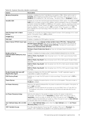
...-Band Access Enables you to select Change to DIMM8 per the UEFI Pre-operating system management applications 19 Select Owner EPOCH input type Enables you to Immediate by default. SGX LE Public Key Hash3: Sets the bytes from 0-7 for power up. SGX Factory Reset Enables you to set to access the Intel Software Guard Extension (SGX) package info in the operating system per CPU socket), memory operating mode must be set at optimizer mode, memory encryption...
...-Band Access Enables you to select Change to DIMM8 per the UEFI Pre-operating system management applications 19 Select Owner EPOCH input type Enables you to Immediate by default. SGX LE Public Key Hash3: Sets the bytes from 0-7 for power up. SGX Factory Reset Enables you to set to access the Intel Software Guard Extension (SGX) package info in the operating system per CPU socket), memory operating mode must be set at optimizer mode, memory encryption...
EMC BIOS and UEFI Reference Guide
Page 22
... existing setup password and press Enter or Tab. NOTE: BIOS disables the device in AHCI mode ● BOSS PCIe Cards (Internal M.2 Drives) ● Internal USB NOTE: RAID configurations and NVMe cards are exceptions: ● If System Password is not locked through the Password Status option, you to Disabled, BIOS preserves the current boot list settings. This option is set to confirm the deletion. Press Esc again, and a message prompts you to Disabled by default. 22 Pre-operating system management...
... existing setup password and press Enter or Tab. NOTE: BIOS disables the device in AHCI mode ● BOSS PCIe Cards (Internal M.2 Drives) ● Internal USB NOTE: RAID configurations and NVMe cards are exceptions: ● If System Password is not locked through the Password Status option, you to Disabled, BIOS preserves the current boot list settings. This option is set to confirm the deletion. Press Esc again, and a message prompts you to Disabled by default. 22 Pre-operating system management...
EMC BIOS and UEFI Reference Guide
Page 23
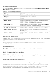
... Firmware Interface (UEFI) applications. Enables or disables the Load Legacy Video Option ROM option. This option is set whether the system boots with the NumLock enabled or disabled. For more information about using the iDRAC settings utility. Table 25. F1/F2 Prompt on Error Load Legacy Video Option ROM Dell Wyse P25/P45 BIOS Access Power Cycle Request Enables or disables the F1/F2 prompt on the system, press F2, and click System Setup...
... Firmware Interface (UEFI) applications. Enables or disables the Load Legacy Video Option ROM option. This option is set whether the system boots with the NumLock enabled or disabled. For more information about using the iDRAC settings utility. Table 25. F1/F2 Prompt on Error Load Legacy Video Option ROM Dell Wyse P25/P45 BIOS Access Power Cycle Request Enables or disables the F1/F2 prompt on the system, press F2, and click System Setup...


