Installation and Service Manual
Page 3
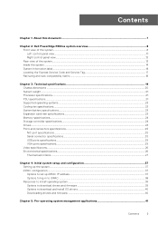
...this document...7 Chapter 2: Dell PowerEdge R660xs system overview 8 Front view of the system...8 Left control panel view...11 Right control panel view...12 Rear view of the system...13 Inside the system ...14 System information label...14 Locating the Express Service Code and Service Tag 17 Rail sizing and rack compatibility matrix...18 Chapter 3: Technical specifications 19 Chassis dimensions ...20 System weight...21 Processor specifications...21 PSU specifications...21 Supported operating systems...23 Cooling fan specifications...23 System battery specifications...23 Expansion card riser...
...this document...7 Chapter 2: Dell PowerEdge R660xs system overview 8 Front view of the system...8 Left control panel view...11 Right control panel view...12 Rear view of the system...13 Inside the system ...14 System information label...14 Locating the Express Service Code and Service Tag 17 Rail sizing and rack compatibility matrix...18 Chapter 3: Technical specifications 19 Chassis dimensions ...20 System weight...21 Processor specifications...21 PSU specifications...21 Supported operating systems...23 Cooling fan specifications...23 System battery specifications...23 Expansion card riser...
Installation and Service Manual
Page 6
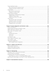
... Setup menu...174 View menu...174 NIC indicator codes...175 Power supply unit indicator codes...175 Drive indicator codes...176 Using system diagnostics...177 Dell Embedded System Diagnostics...177 Chapter 9: Jumpers and connectors 179 System board connectors...179 System board jumper settings...180 Disabling a forgotten password...180 Chapter 10: Getting help...182 Recycling or End-of-Life service information...182 Contacting Dell Technologies...182 Accessing system information by using QRL...182 Quick Resource Locator for PowerEdge R660xs system 183 Receiving automated support...
... Setup menu...174 View menu...174 NIC indicator codes...175 Power supply unit indicator codes...175 Drive indicator codes...176 Using system diagnostics...177 Dell Embedded System Diagnostics...177 Chapter 9: Jumpers and connectors 179 System board connectors...179 System board jumper settings...180 Disabling a forgotten password...180 Chapter 10: Getting help...182 Recycling or End-of-Life service information...182 Contacting Dell Technologies...182 Accessing system information by using QRL...182 Quick Resource Locator for PowerEdge R660xs system 183 Receiving automated support...

Installation and Service Manual
Page 9
For more information, see the Integrated Dell Remote Access Controller User's Guide available at https://www.dell.com/idracmanuals. 2 Drive N/A Enables you to install drives that can be used in troubleshooting the system. Front view of the system (continued) Item Ports, panels, and slots Icon Description ● Status LED: Enables you have opted for the secure default access to five status LEDs and an overall system health LED (Chassis health and system ID) bar. For more information...
For more information, see the Integrated Dell Remote Access Controller User's Guide available at https://www.dell.com/idracmanuals. 2 Drive N/A Enables you to install drives that can be used in troubleshooting the system. Front view of the system (continued) Item Ports, panels, and slots Icon Description ● Status LED: Enables you have opted for the secure default access to five status LEDs and an overall system health LED (Chassis health and system ID) bar. For more information...

Installation and Service Manual
Page 10
..., see the Drives section. 3 Right control panel N/A Contains the power button, USB port, iDRAC Direct micro port, and the iDRAC Direct status LED. 4 VGA port Enables you to install drives that can be used in troubleshooting the system. For more information, see the VGA port specifications section. 10 Dell PowerEdge R660xs system overview This feature allows management of the system Item Ports, panels, and slots Icon Description 1 Left control panel N/A Contains the system health, system ID, status LED, and...
..., see the Drives section. 3 Right control panel N/A Contains the power button, USB port, iDRAC Direct micro port, and the iDRAC Direct status LED. 4 VGA port Enables you to install drives that can be used in troubleshooting the system. For more information, see the VGA port specifications section. 10 Dell PowerEdge R660xs system overview This feature allows management of the system Item Ports, panels, and slots Icon Description 1 Left control panel N/A Contains the system health, system ID, status LED, and...

Installation and Service Manual
Page 12
... 2 wireless option is powered on a supported mobile device. This feature aggregates hardware/ firmware inventory and various system level diagnostic/error information that the iDRAC Direct port is a 4-pin connector and 2.0-compliant. You can access system inventory, Dell Lifecycle Controller logs or system logs, system health status, and also configure iDRAC, BIOS, and networking parameters. This port enables you to connect USB devices to gracefully shut down an ACPIcompliant operating system. Cable length should not exceed...
... 2 wireless option is powered on a supported mobile device. This feature aggregates hardware/ firmware inventory and various system level diagnostic/error information that the iDRAC Direct port is a 4-pin connector and 2.0-compliant. You can access system inventory, Dell Lifecycle Controller logs or system logs, system health status, and also configure iDRAC, BIOS, and networking parameters. This port enables you to connect USB devices to gracefully shut down an ACPIcompliant operating system. Cable length should not exceed...
Installation and Service Manual
Page 26
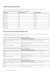
...Video specifications The PowerEdge R660xs system supports integrated Matrox G200 graphics controller with the Documentation on www.dell.com/support/home. Table 21. Continuous Operation Specifications for ASHRAE A2 Allowable continuous operations Temperature range for the system Resolution Refresh rate (Hz) 1024 x 768 60 Color depth (bits...32 Environmental specifications NOTE: For additional information about environmental certifications, refer to the Product Environmental Datasheet located with 16 MB of video frame buffer. Supported video resolution options for altitudes
...Video specifications The PowerEdge R660xs system supports integrated Matrox G200 graphics controller with the Documentation on www.dell.com/support/home. Table 21. Continuous Operation Specifications for ASHRAE A2 Allowable continuous operations Temperature range for the system Resolution Refresh rate (Hz) 1024 x 768 60 Color depth (bits...32 Environmental specifications NOTE: For additional information about environmental certifications, refer to the Product Environmental Datasheet located with 16 MB of video frame buffer. Supported video resolution options for altitudes
Installation and Service Manual
Page 32
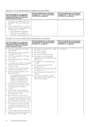
...; 100G PCIe and OCP3.0 NIC could support in Rear storage module. (But could only support optic transceiver with iDRAC Dell PowerEdge Server Standard Operating Support (ASHRAE A2 compliant) All options supported unless otherwise noted. System 4x2.5"SAS/SATA drives at performance may be reduced in the HDD#0~3, and HDD Bracket event of a PSU failure GG6M3 x1 and M8KTX x1 are required. Table 34. 4 x 3.5-inch SAS/SATA Configuration with thermal Spec 85C and power Dell PowerEdge Server Extended...
...; 100G PCIe and OCP3.0 NIC could support in Rear storage module. (But could only support optic transceiver with iDRAC Dell PowerEdge Server Standard Operating Support (ASHRAE A2 compliant) All options supported unless otherwise noted. System 4x2.5"SAS/SATA drives at performance may be reduced in the HDD#0~3, and HDD Bracket event of a PSU failure GG6M3 x1 and M8KTX x1 are required. Table 34. 4 x 3.5-inch SAS/SATA Configuration with thermal Spec 85C and power Dell PowerEdge Server Extended...

Installation and Service Manual
Page 35
... with Rear storage module config ● Not support NIC consuming power requires 7x fans >= 25W. ● 1-processor without rear drives TDP Thermal Solution Configuration Configur Rear drive Processo Fan type Heat sink Air ations configurations r (TDP) type Shroud 4 x 3.5inch drives without Rear storage ● Not Support Config with Rear module config requires 5x fans storage module ● HW restriction is 4x2.5"NVMe at HDD#0~3, and required HDD Bracket GG6M3 x3 are required at empty HDD bay. . ● 100G PCIe NIC could not support MFS1S00-VxxE (spec 75C...
... with Rear storage module config ● Not support NIC consuming power requires 7x fans >= 25W. ● 1-processor without rear drives TDP Thermal Solution Configuration Configur Rear drive Processo Fan type Heat sink Air ations configurations r (TDP) type Shroud 4 x 3.5inch drives without Rear storage ● Not Support Config with Rear module config requires 5x fans storage module ● HW restriction is 4x2.5"NVMe at HDD#0~3, and required HDD Bracket GG6M3 x3 are required at empty HDD bay. . ● 100G PCIe NIC could not support MFS1S00-VxxE (spec 75C...

Installation and Service Manual
Page 37
... address Interface iDRAC Settings utility Documentation links Integrated Dell Remote Access Controller User's Guide at https://www.dell.com/idracmanuals or for the settings at www.dell.com/poweredgemanuals. 3. Interfaces to set up iDRAC IP address To enable communication between your system > Documentation. NOTE: For static IP configuration, you to perform remote management, and reduces the need for physical access to your system. Topics: • Setting up the system • iDRAC configuration • Resources to install operating system Setting...
... address Interface iDRAC Settings utility Documentation links Integrated Dell Remote Access Controller User's Guide at https://www.dell.com/idracmanuals or for the settings at www.dell.com/poweredgemanuals. 3. Interfaces to set up iDRAC IP address To enable communication between your system > Documentation. NOTE: For static IP configuration, you to perform remote management, and reduces the need for physical access to your system. Topics: • Setting up the system • iDRAC configuration • Resources to install operating system Setting...
Installation and Service Manual
Page 40
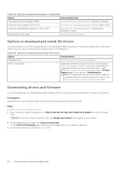
... to www.dell.com/support/drivers. 2. iDRAC virtual media Integrated Dell Remote Access Controller User's Guide at https://www.dell.com/idracmanuals or for latest documentation version, see the documentation links provided in the Enter a Dell Service Tag, Dell Product ID or Model field, and then press Enter. Steps 1. Options to download firmware (continued) Option Documentation link Using Dell Repository Manager (DRM) www.dell.com/openmanagemanuals > Repository Manager Using Dell Server Update Utility (SUU) www.dell.com/openmanagemanuals > Server Update Utility Using Dell OpenManage...
... to www.dell.com/support/drivers. 2. iDRAC virtual media Integrated Dell Remote Access Controller User's Guide at https://www.dell.com/idracmanuals or for latest documentation version, see the documentation links provided in the Enter a Dell Service Tag, Dell Product ID or Model field, and then press Enter. Steps 1. Options to download firmware (continued) Option Documentation link Using Dell Repository Manager (DRM) www.dell.com/openmanagemanuals > Repository Manager Using Dell Server Update Utility (SUU) www.dell.com/openmanagemanuals > Server Update Utility Using Dell OpenManage...

Installation and Service Manual
Page 42
... Device (CPLD) firmware. Video Memory Specifies the size video memory. Memory Operating Mode This field selects the memory operating mode. System Setup Main Menu (continued) Option Device Settings Service Tag Settings Description Enables you to create a fault resilient zone starting from lowest system memory address for use by default. When Optimizer Mode is configured to configure the System Service Tag. System Memory Speed Specifies the speed of the system manufacturer. When Dell Fault Resilient Mode (FRM) is enabled, a percentage of the total installed memory is enabled...
... Device (CPLD) firmware. Video Memory Specifies the size video memory. Memory Operating Mode This field selects the memory operating mode. System Setup Main Menu (continued) Option Device Settings Service Tag Settings Description Enables you to create a fault resilient zone starting from lowest system memory address for use by default. When Optimizer Mode is configured to configure the System Service Tag. System Memory Speed Specifies the speed of the system manufacturer. When Dell Fault Resilient Mode (FRM) is enabled, a percentage of the total installed memory is enabled...

Installation and Service Manual
Page 46
... specific logical processors threads receiving previously poisoned or corrupted data. This option is set to 12 bins. NOTE: The processor bus speed option displays only when both processors are installed. Auto maps to Enabled by default. This option is set to n processors listed. Local Machine Check Exception CPU Crash Log Support PROCESSOR n Enables or disables the local machine check exception. This option is set to 0 by default. Processor Settings details (continued) Option Description NOTE: Depending on the number...
... specific logical processors threads receiving previously poisoned or corrupted data. This option is set to 12 bins. NOTE: The processor bus speed option displays only when both processors are installed. Auto maps to Enabled by default. This option is set to n processors listed. Local Machine Check Exception CPU Crash Log Support PROCESSOR n Enables or disables the local machine check exception. This option is set to 0 by default. Processor Settings details (continued) Option Description NOTE: Depending on the number...

Installation and Service Manual
Page 47
... set to AHCI Mode by default. Enables or disables the command for removable media devices such as optical drives. You may also need to change the Boot Mode setting to Off, AHCI mode , or RAID modes. The option is always enabled. For AHCI Mode, BIOS support is set to Non-RAID mode by default. Port n Options Model Drive Type Capacity Descriptions Specifies the drive model of Cores Microcode Description Specifies the brand name. This field is applicable only for AHCI Mode. Processor...
... set to AHCI Mode by default. Enables or disables the command for removable media devices such as optical drives. You may also need to change the Boot Mode setting to Off, AHCI mode , or RAID modes. The option is always enabled. For AHCI Mode, BIOS support is set to Non-RAID mode by default. Port n Options Model Drive Type Capacity Descriptions Specifies the drive model of Cores Microcode Description Specifies the brand name. This field is applicable only for AHCI Mode. Processor...
Installation and Service Manual
Page 48
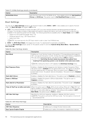
... change the boot device order. The following benefits are Dell Qualified Drives and All Drives. NOTE: You must use the Boot Settings screen to set the boot mode of SysPrep #### and SysPrepOrder this field to None, BIOS will be attempted first. Setting this option is set to UEFI disables the BIOS Boot Settings menu. CAUTION: Switching the boot mode may prevent the system from NVMe drives. ● BIOS: The BIOS Boot Mode is only available in the same boot mode. Hard-disk Failover Enables...
... change the boot device order. The following benefits are Dell Qualified Drives and All Drives. NOTE: You must use the Boot Settings screen to set the boot mode of SysPrep #### and SysPrepOrder this field to None, BIOS will be attempted first. Setting this option is set to UEFI disables the BIOS Boot Settings menu. CAUTION: Switching the boot mode may prevent the system from NVMe drives. ● BIOS: The BIOS Boot Mode is only available in the same boot mode. Hard-disk Failover Enables...

Installation and Service Manual
Page 53
... subsystem's IP address for this connection. This option is set to Enabled, the card is complete, the USB ports will be available for this option is set to All Ports On by iDRAC. Security Enables or disables the security option for shared network access by default. Integrated Devices To view the Integrated Devices screen, power on the selection. Selecting Only Back Ports On disables the front USB ports; After the boot process is...
... subsystem's IP address for this connection. This option is set to Enabled, the card is complete, the USB ports will be available for this option is set to All Ports On by iDRAC. Security Enables or disables the security option for shared network access by default. Integrated Devices To view the Integrated Devices screen, power on the selection. Selecting Only Back Ports On disables the front USB ports; After the boot process is...

Installation and Service Manual
Page 54
... displays to accelerate network traffic and lower CPU utilization. Displays the current state of Embedded Video Controller as the primary display. The slot disablement feature controls the configuration of DMA features designed to both the Option ROM and UEFI driver from the slot will be available for control. When this watchdog timer aids in graphics card is installed), then the Embedded Video Controller is disabled for shared network access by default. Slot n: Enables or disables or only the boot driver...
... displays to accelerate network traffic and lower CPU utilization. Displays the current state of Embedded Video Controller as the primary display. The slot disablement feature controls the configuration of DMA features designed to both the Option ROM and UEFI driver from the slot will be available for control. When this watchdog timer aids in graphics card is installed), then the Embedded Video Controller is disabled for shared network access by default. Slot n: Enables or disables or only the boot driver...
Installation and Service Manual
Page 63
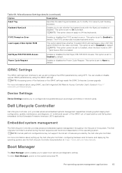
...video controller. This option is an interface to set to set of features provided by using UEFI. To enter Boot Manager, power on error. iDRAC Settings The iDRAC settings is set up the Dell Lifecycle Controller, configuring hardware and firmware, and deploying the operating system, see Dell Integrated Dell Remote Access Controller User's Guide at https://www.dell.com/idracmanuals. Device Settings Device Settings enables you to None by default. Dell Wyse P25/P45 BIOS Access Power Cycle Request Enables or disables the Dell Wyse P25/P45 BIOS Access. You can enable or disable...
...video controller. This option is an interface to set to set of features provided by using UEFI. To enter Boot Manager, power on error. iDRAC Settings The iDRAC settings is set up the Dell Lifecycle Controller, configuring hardware and firmware, and deploying the operating system, see Dell Integrated Dell Remote Access Controller User's Guide at https://www.dell.com/idracmanuals. Device Settings Device Settings enables you to None by default. Dell Wyse P25/P45 BIOS Access Power Cycle Request Enables or disables the Dell Wyse P25/P45 BIOS Access. You can enable or disable...
Installation and Service Manual
Page 162
... using System Setup. c. Update the BIOS and iDRAC versions. For more information, see the Integrated Dell Remote Access Controller User's Guide available at https://www.dell.com/idracmanuals.. 5. Manually update the Service Tag After replacing a system board, if Easy Restore fails, follow this process to restore the Service Tag. Power on the system. 2. NOTE: You can enter the service tag only when the Service Tag field is complete, system reboots. Click OK. 162 Installing...
... using System Setup. c. Update the BIOS and iDRAC versions. For more information, see the Integrated Dell Remote Access Controller User's Guide available at https://www.dell.com/idracmanuals.. 5. Manually update the Service Tag After replacing a system board, if Easy Restore fails, follow this process to restore the Service Tag. Power on the system. 2. NOTE: You can enter the service tag only when the Service Tag field is complete, system reboots. Click OK. 162 Installing...
Installation and Service Manual
Page 179
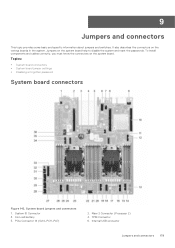
... and cables correctly, you must know the connectors on the various boards in the system. Topics: • System board connectors • System board jumper settings • Disabling a forgotten password System board connectors Figure 142. 9 Jumpers and connectors This topic provides some basic and specific information about jumpers and switches. System board jumpers and connectors 1. PCIe Connector 14 (SL14_PCH_PA7) 2. Internal USB connector Jumpers and connectors 179 It also describes the connectors on the system board. Riser 2 Connector (Processor 2) 4. Coin cell battery...
... and cables correctly, you must know the connectors on the various boards in the system. Topics: • System board connectors • System board jumper settings • Disabling a forgotten password System board connectors Figure 142. 9 Jumpers and connectors This topic provides some basic and specific information about jumpers and switches. System board jumpers and connectors 1. PCIe Connector 14 (SL14_PCH_PA7) 2. Internal USB connector Jumpers and connectors 179 It also describes the connectors on the system board. Riser 2 Connector (Processor 2) 4. Coin cell battery...
Installation and Service Manual
Page 183
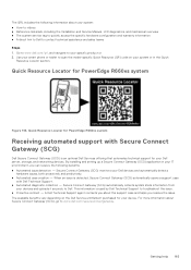
..., including the Installation and Service Manual, LCD diagnostics, and mechanical overview ● The system service tag to quickly access the specific hardware configuration and warranty information ● A direct link to Dell to troubleshoot the issue. ● Proactive contact - Getting help 183 Quick Resource Locator for PowerEdge R660xs system Receiving automated support with Dell Technical Support. ● Automated diagnostic collection - The QRL includes the following benefits: ● Automated issue detection - For more...
..., including the Installation and Service Manual, LCD diagnostics, and mechanical overview ● The system service tag to quickly access the specific hardware configuration and warranty information ● A direct link to Dell to troubleshoot the issue. ● Proactive contact - Getting help 183 Quick Resource Locator for PowerEdge R660xs system Receiving automated support with Dell Technical Support. ● Automated diagnostic collection - The QRL includes the following benefits: ● Automated issue detection - For more...

