
Glossary
Page 1
ANSI - asset tag - A copy of data or instructions for quick data retrieval. A module that includes power supplies and fans. Baseboard management controller. bus - Your system also contains an address bus and a data bus for security or tracking purposes. A...processor and RAM. CIM - American National Standards Institute. A CD, diskette, or USB memory key that allows the processor to the system. Celsius. Dell™ Glossary NOTE: For additional information on storage terminology, visit the Storage Networking Industry Association's website at www.snia.org and click on a ...
ANSI - asset tag - A copy of data or instructions for quick data retrieval. A module that includes power supplies and fans. Baseboard management controller. bus - Your system also contains an address bus and a data bus for security or tracking purposes. A...processor and RAM. CIM - American National Standards Institute. A CD, diskette, or USB memory key that allows the processor to the system. Celsius. Dell™ Glossary NOTE: For additional information on storage terminology, visit the Storage Networking Industry Association's website at www.snia.org and click on a ...

Glossary
Page 8
...Serial Bus. Because the System Setup program is installed and how the system should be terminated to remotely monitor and manage workstations. Uninterruptible power supply. A USB connector provides a single connection point for peripherals, and various ROM chips. Used to describe a system that allows you change... switch settings on the devices or by setting features such as mice and keyboards. Data stored in memory that automatically supplies power to configure your system's hardware and customize the system's operation by changing settings in effect until you to your system...
...Serial Bus. Because the System Setup program is installed and how the system should be terminated to remotely monitor and manage workstations. Uninterruptible power supply. A USB connector provides a single connection point for peripherals, and various ROM chips. Used to describe a system that allows you change... switch settings on the devices or by setting features such as mice and keyboards. Data stored in memory that automatically supplies power to configure your system's hardware and customize the system's operation by changing settings in effect until you to your system...

Glossary
Page 48
Uninterruptible power supply USB - Simple Network Management Protocol SVGA - Watt WH - Unregistered DDR3 UPS - Volt direct current VGA - Self-Monitoring Analysis and Reporting Technology BIOS SMP - Universal Serial ...
Uninterruptible power supply USB - Simple Network Management Protocol SVGA - Watt WH - Unregistered DDR3 UPS - Volt direct current VGA - Self-Monitoring Analysis and Reporting Technology BIOS SMP - Universal Serial ...

Glossary
Page 58
... provider CIM management station managed system) 은 Dell OpenManage™ Server Administrator x x y x z 58 SVGA Super Video Graphics Array VGA 와 SVGA TCP/IP Transmission Control Protocol/Internet Protocol TOE - TCP/IP TCP/IP Offload Engine U-DIMM DDR3 Unregistered(Unbuffered) DDR3 Memory Module UPS Uninterruptible Power Supply USB Universal Serial Bus USB USB USB...
... provider CIM management station managed system) 은 Dell OpenManage™ Server Administrator x x y x z 58 SVGA Super Video Graphics Array VGA 와 SVGA TCP/IP Transmission Control Protocol/Internet Protocol TOE - TCP/IP TCP/IP Offload Engine U-DIMM DDR3 Unregistered(Unbuffered) DDR3 Memory Module UPS Uninterruptible Power Supply USB Universal Serial Bus USB USB USB...
Getting Started Guide
Page 4
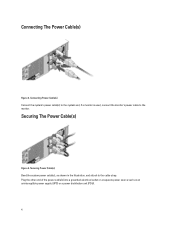
Connecting The Power Cable(s) Figure 3. Connecting Power Cable(s) Connect the system's power cable(s) to the system and, if a monitor is used, connect the monitor's power cable to the cable strap. Securing Power Cable(s) Bend the system power cable(s), as an uninterruptible power supply (UPS) or a power distribution unit (PDU). 4 Plug the other end of the power cable(s) into a grounded electrical outlet or a separate power source such as shown in the illustration, and attach to the monitor. Securing The Power Cable(s) Figure 4.
Connecting The Power Cable(s) Figure 3. Connecting Power Cable(s) Connect the system's power cable(s) to the system and, if a monitor is used, connect the monitor's power cable to the cable strap. Securing Power Cable(s) Bend the system power cable(s), as an uninterruptible power supply (UPS) or a power distribution unit (PDU). 4 Plug the other end of the power cable(s) into a grounded electrical outlet or a separate power source such as shown in the illustration, and attach to the monitor. Securing The Power Cable(s) Figure 4.
Getting Started Guide
Page 6
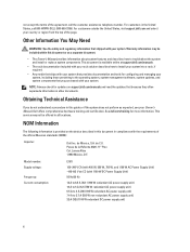
... training and certification. NOM Information The following information is available online at support.dell.com/manuals. • The rack documentation included with your rack solution describes how to 3.7 A (550 W non-redundant AC power supply unit) 32 A (X2) (1100 W redundant DC power supply unit) 6 Warranty information may not be included within this guide or if the...
... training and certification. NOM Information The following information is available online at support.dell.com/manuals. • The rack documentation included with your rack solution describes how to 3.7 A (550 W non-redundant AC power supply unit) 32 A (X2) (1100 W redundant DC power supply unit) 6 Warranty information may not be included within this guide or if the...

Getting Started Guide
Page 7
... of the specifications for your system. Technical Specifications NOTE: The following specifications are only those required by law to ship with a phase to support.dell.com. Power AC Power Supply (per power supply) Wattage 495 W, 550 W, 750 W, or 1100 W AC power supply unit Heat dissipation 1908 BTU/hr maximum (495 W redundant power supply) NOTE: Heat dissipation is calculated using the...
... of the specifications for your system. Technical Specifications NOTE: The following specifications are only those required by law to ship with a phase to support.dell.com. Power AC Power Supply (per power supply) Wattage 495 W, 550 W, 750 W, or 1100 W AC power supply unit Heat dissipation 1908 BTU/hr maximum (495 W redundant power supply) NOTE: Heat dissipation is calculated using the...
Owner's Manual
Page 3
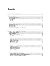
... Setup Menu...12 View Menu...12 Hard-Drive Indicator Patterns...13 Back-Panel Features And Indicators...14 NIC Indicator Codes...15 Power Indicator Codes...15 Power Indicator Codes For Non-Redundant Power Supply 17 Other Information You May Need...18 2 Using The System Setup And Boot Manager 19 Choosing The System Boot Mode...19...
... Setup Menu...12 View Menu...12 Hard-Drive Indicator Patterns...13 Back-Panel Features And Indicators...14 NIC Indicator Codes...15 Power Indicator Codes...15 Power Indicator Codes For Non-Redundant Power Supply 17 Other Information You May Need...18 2 Using The System Setup And Boot Manager 19 Choosing The System Boot Mode...19...
Owner's Manual
Page 5
... A Processor...70 Installing A Processor...72 Power Supplies...73 Removing An AC Power Supply...74 Installing An AC Power Supply...75 Wiring Instructions For A DC Power Supply...75 Removing A DC Power Supply...78 Installing A DC Power Supply...79 Removing The Power Supply Blank...79 Installing The Power Supply Blank...80 Removing The Power-Distribution And Power-Interposer Boards 80 Installing The Power-Distribution And Power-Interposer Boards 83 Removing A Non-Redundant...
... A Processor...70 Installing A Processor...72 Power Supplies...73 Removing An AC Power Supply...74 Installing An AC Power Supply...75 Wiring Instructions For A DC Power Supply...75 Removing A DC Power Supply...78 Installing A DC Power Supply...79 Removing The Power Supply Blank...79 Installing The Power Supply Blank...80 Removing The Power-Distribution And Power-Interposer Boards 80 Installing The Power-Distribution And Power-Interposer Boards 83 Removing A Non-Redundant...
Owner's Manual
Page 6
... Serial I/O Device...100 Troubleshooting A NIC...100 Troubleshooting A Wet System...100 Troubleshooting A Damaged System...101 Troubleshooting The System Battery...102 Troubleshooting Power Supplies...102 Troubleshooting Cooling Problems...102 Troubleshooting Cooling Fans...103 Troubleshooting System Memory...103 Troubleshooting An Internal USB Key...104 Troubleshooting An SD Card...104 Troubleshooting...A Hard Drive...105 Troubleshooting A Storage Controller...106 Troubleshooting Expansion Cards...106 Troubleshooting Processors...107 5 Using System Diagnostics...109 Dell Online Diagnostics...109
... Serial I/O Device...100 Troubleshooting A NIC...100 Troubleshooting A Wet System...100 Troubleshooting A Damaged System...101 Troubleshooting The System Battery...102 Troubleshooting Power Supplies...102 Troubleshooting Cooling Problems...102 Troubleshooting Cooling Fans...103 Troubleshooting System Memory...103 Troubleshooting An Internal USB Key...104 Troubleshooting An SD Card...104 Troubleshooting...A Hard Drive...105 Troubleshooting A Storage Controller...106 Troubleshooting Expansion Cards...106 Troubleshooting Processors...107 5 Using System Diagnostics...109 Dell Online Diagnostics...109
Owner's Manual
Page 9
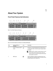
... RAID System Item Indicator, Button, or Icon Description Connector 1 Power-on indicator, power button The power-on . Front-Panel Features and Indicators Figure 2. NOTE: On ACPI-compliant operating systems, turning off the system using the end of a paper clip. 9 The power button controls the power supply output to troubleshoot software and device driver errors when using...
... RAID System Item Indicator, Button, or Icon Description Connector 1 Power-on indicator, power button The power-on . Front-Panel Features and Indicators Figure 2. NOTE: On ACPI-compliant operating systems, turning off the system using the end of a paper clip. 9 The power button controls the power supply output to troubleshoot software and device driver errors when using...
Owner's Manual
Page 14
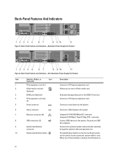
Connects the optional system status indicator assembly through the optional cable management arm. Back-Panel Features and Indicators-Redundant Power Supply Unit Chassis Figure 6. When one of these buttons is pushed, the LCD panel on the front and back panels can be ...used to the system. Back-Panel Features and Indicators-Non-Redundant Power Supply Unit Chassis Item Indicator, Button, or Icon Description Connector 1 PCIe expansion card slot 1 Connects a PCI Express expansion card. 2 vFlash media card slot...
Connects the optional system status indicator assembly through the optional cable management arm. Back-Panel Features and Indicators-Redundant Power Supply Unit Chassis Figure 6. When one of these buttons is pushed, the LCD panel on the front and back panels can be ...used to the system. Back-Panel Features and Indicators-Non-Redundant Power Supply Unit Chassis Item Indicator, Button, or Icon Description Connector 1 PCIe expansion card slot 1 Connects a PCI Express expansion card. 2 vFlash media card slot...
Owner's Manual
Page 15
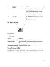
If the system hangs during POST, press and hold for more than 15 seconds. 11 Power supply AC 495 W, 750 W, 1100 W or 550 W (non-redundant), Or DC 1100 W (when available), NIC Indicator Codes Figure 7. Link indicator is green The NIC is ...are off . Press to a valid network at less than five seconds to a valid network at its maximum port speed. Power Indicator Codes Each AC power supply has an illuminated translucent handle and each DC power supply (when available) has an LED that serves as an indicator to the network. Activity indicator is blinking green Network...
If the system hangs during POST, press and hold for more than 15 seconds. 11 Power supply AC 495 W, 750 W, 1100 W or 550 W (non-redundant), Or DC 1100 W (when available), NIC Indicator Codes Figure 7. Link indicator is green The NIC is ...are off . Press to a valid network at less than five seconds to a valid network at its maximum port speed. Power Indicator Codes Each AC power supply has an illuminated translucent handle and each DC power supply (when available) has an LED that serves as an indicator to the network. Activity indicator is blinking green Network...
Owner's Manual
Page 16
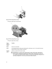
... To change from a High Output configuration to the power supply and that the power supply is not connected. AC power supply status indicator/handle Figure 9. DC power supply status indicator Power Indicator Pattern Not lit Green Flashing amber Condition Power is operational. CAUTION: When correcting a power supply mismatch, replace only the power supply with the power supply. AC Power Supply Status Indicator 1. Indicates a problem with the flashing indicator...
... To change from a High Output configuration to the power supply and that the power supply is not connected. AC power supply status indicator/handle Figure 9. DC power supply status indicator Power Indicator Pattern Not lit Green Flashing amber Condition Power is operational. CAUTION: When correcting a power supply mismatch, replace only the power supply with the power supply. AC Power Supply Status Indicator 1. Indicates a problem with the flashing indicator...
Owner's Manual
Page 17
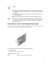
... different input voltages, they must be of the other power supply (in terms of the system. Flashing green When hot-adding a power supply, this indicates that the power supply is used , they can output different wattages, and trigger a mismatch. Power Indicator Codes For Non-Redundant Power Supply The non-redundant power supply has a status indicator and a self-diagnostic button. CAUTION: If...
... different input voltages, they must be of the other power supply (in terms of the system. Flashing green When hot-adding a power supply, this indicates that the power supply is used , they can output different wattages, and trigger a mismatch. Power Indicator Codes For Non-Redundant Power Supply The non-redundant power supply has a status indicator and a self-diagnostic button. CAUTION: If...

Owner's Manual
Page 18
... with your system. NOTE: Always check for configuring and managing your system, including those pertaining to the power supply and the power supply is operational. Warranty information may be included within this document, see the Glossary at support.dell.com/manuals. • The rack documentation included with your rack solution describes how to install your...
... with your system. NOTE: Always check for configuring and managing your system, including those pertaining to the power supply and the power supply is operational. Warranty information may be included within this document, see the Glossary at support.dell.com/manuals. • The rack documentation included with your rack solution describes how to install your...
Owner's Manual
Page 33
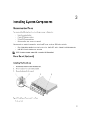
...; #1 and #2 Phillips screwdrivers • T10 and T15 Torx screwdrivers • Wrist grounding strap connected to ground Following tools are required for assembling cables for a DC power supply unit (PSU), when available: • Wire-stripper pliers capable of the bezel onto the system. 3. Fit the free end of removing insulation from size 10...
...; #1 and #2 Phillips screwdrivers • T10 and T15 Torx screwdrivers • Wrist grounding strap connected to ground Following tools are required for assembling cables for a DC power supply unit (PSU), when available: • Wire-stripper pliers capable of the bezel onto the system. 3. Fit the free end of removing insulation from size 10...
Owner's Manual
Page 36
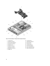
expansion-card riser 2 5. expansion card 6. optical drive (optional) 12. hard drives (8) 13. power-distribution board 17. Inside the System-Redundant Power Supply Unit Chassis 1. power supply (redundant) 4. control-panel board 15. power-interposer board 36 heat sink for processor 1 9. information tag 14. expansion-card riser 1 8. cooling fans (6) 11. expansion-card latch 3. expansion-card latch 7. hard-drive backplane 16. cooling shroud 2. DIMMs (12) 10. Figure 13.
expansion-card riser 2 5. expansion card 6. optical drive (optional) 12. hard drives (8) 13. power-distribution board 17. Inside the System-Redundant Power Supply Unit Chassis 1. power supply (redundant) 4. control-panel board 15. power-interposer board 36 heat sink for processor 1 9. information tag 14. expansion-card riser 1 8. cooling fans (6) 11. expansion-card latch 3. expansion-card latch 7. hard-drive backplane 16. cooling shroud 2. DIMMs (12) 10. Figure 13.
Owner's Manual
Page 37
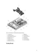
Inside the System-Non-Redundant Power Supply Unit Chassis 1. cooling shroud 2. power supply (non-redundant) 4. expansion-card latch 7. DIMMs (12) 10. optical drive (optional) 12. cooling fans (6) 11. hard-drive backplane Cooling Shroud 37 expansion-card riser 2 5. heat sink for processor 1 9. information tag 14. expansion card 6. hard drives (8) 13. expansion-card riser 1 8. control-panel board 15. expansion-card latch 3. Figure 14.
Inside the System-Non-Redundant Power Supply Unit Chassis 1. cooling shroud 2. power supply (non-redundant) 4. expansion-card latch 7. DIMMs (12) 10. optical drive (optional) 12. cooling fans (6) 11. hard-drive backplane Cooling Shroud 37 expansion-card riser 2 5. heat sink for processor 1 9. information tag 14. expansion card 6. hard drives (8) 13. expansion-card riser 1 8. control-panel board 15. expansion-card latch 3. Figure 14.
Owner's Manual
Page 67
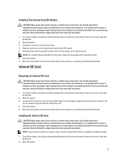
...module until it from the slot and remove the card. 4. Installing An Internal SD Card CAUTION: Many repairs may only be done by Dell is firmly seated on , including any attached peripherals, and disconnect the system from the electrical outlet and peripherals. 2. Damage due to ... card with your product documentation, or as directed by Dell is enabled in your product documentation, or as authorized in the System Setup. 1. Turn off the system, including any attached peripherals, and disconnect the system from the power supply unit cage supports the dual SD module. 6. Damage ...
...module until it from the slot and remove the card. 4. Installing An Internal SD Card CAUTION: Many repairs may only be done by Dell is firmly seated on , including any attached peripherals, and disconnect the system from the electrical outlet and peripherals. 2. Damage due to ... card with your product documentation, or as directed by Dell is enabled in your product documentation, or as authorized in the System Setup. 1. Turn off the system, including any attached peripherals, and disconnect the system from the power supply unit cage supports the dual SD module. 6. Damage ...


