
Glossary
Page 1
... the system will not boot from SNMP agents. ACPI - ANSI - A CD, diskette, or USB memory key that includes power supplies and fans. A - backup - American National Standards Institute. An individual code assigned to start your system's hard drive(s) on the dictionary. CIM - ..., for quick data retrieval. Your system also contains an address bus and a data bus for developing technology standards in the U.S. Dell™ Glossary NOTE: For additional information on storage terminology, visit the Storage Networking Industry Association's website at www.snia.org and ...
... the system will not boot from SNMP agents. ACPI - ANSI - A CD, diskette, or USB memory key that includes power supplies and fans. A - backup - American National Standards Institute. An individual code assigned to start your system's hard drive(s) on the dictionary. CIM - ..., for quick data retrieval. Your system also contains an address bus and a data bus for developing technology standards in the U.S. Dell™ Glossary NOTE: For additional information on storage terminology, visit the Storage Networking Industry Association's website at www.snia.org and ...

Glossary
Page 3
... riser board for connection of electronic chip that can be programmed and reprogrammed using a software utility. hot-plug - Hz - iDRAC - Integrated Dell Remote Access Controller. expansion-card connector - A type of processors with networked storage devices. The FSB is an output device. Gb - A... board and storage devices. InfiniBand - InfiniBand offers point-to insert or install a device, typically a hard drive or an internal cooling fan, into the host system while the system is usually rounded to organize and keep track of file storage. FAT - Fibre Channel - ...
... riser board for connection of electronic chip that can be programmed and reprogrammed using a software utility. hot-plug - Hz - iDRAC - Integrated Dell Remote Access Controller. expansion-card connector - A type of processors with networked storage devices. The FSB is an output device. Gb - A... board and storage devices. InfiniBand - InfiniBand offers point-to insert or install a device, typically a hard drive or an internal cooling fan, into the host system while the system is usually rounded to organize and keep track of file storage. FAT - Fibre Channel - ...
User Manual
Page 3
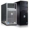
...information for installing the second processor in Dell PowerEdge R520 and PowerEdge R420 systems. Before You Begin To install a second processor in your system configuration, verify the system power consumption with a cooling fan. Riser Upgrade Information PowerEdge System R520 R420 Upgrade From To Riser1_1P: One... x16 link Riser2_1P: One full-height, half-length x16 link Same as indicated in the FAN 6 slot with the Dell Energy Smart Solution Advisor at support.dell.com. Additonal Processor Installation 3 NOTE: When selecting or upgrading your system, you must ensure...
...information for installing the second processor in Dell PowerEdge R520 and PowerEdge R420 systems. Before You Begin To install a second processor in your system configuration, verify the system power consumption with a cooling fan. Riser Upgrade Information PowerEdge System R520 R420 Upgrade From To Riser1_1P: One... x16 link Riser2_1P: One full-height, half-length x16 link Same as indicated in the FAN 6 slot with the Dell Energy Smart Solution Advisor at support.dell.com. Additonal Processor Installation 3 NOTE: When selecting or upgrading your system, you must ensure...
Owner's Manual
Page 5
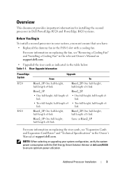
Optical Drive (Optional)...53 Removing The Optical Drive...53 Installing The Optical Drive...54 Cooling Fans...54 Removing A Cooling Fan...54 Installing A Cooling Fan...55 Internal USB Memory Key (Optional)...56 Replacing the Internal USB Key...56 Expansion Cards And Expansion-Card Risers...57 Expansion-Card Installation Guidelines...57 ...
Optical Drive (Optional)...53 Removing The Optical Drive...53 Installing The Optical Drive...54 Cooling Fans...54 Removing A Cooling Fan...54 Installing A Cooling Fan...55 Internal USB Memory Key (Optional)...56 Replacing the Internal USB Key...56 Expansion Cards And Expansion-Card Risers...57 Expansion-Card Installation Guidelines...57 ...
Owner's Manual
Page 6
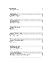
... A NIC...100 Troubleshooting A Wet System...100 Troubleshooting A Damaged System...101 Troubleshooting The System Battery...102 Troubleshooting Power Supplies...102 Troubleshooting Cooling Problems...102 Troubleshooting Cooling Fans...103 Troubleshooting System Memory...103 Troubleshooting An Internal USB Key...104 Troubleshooting An SD Card...104 Troubleshooting An Optical Drive...105 Troubleshooting A Hard Drive...105...
... A NIC...100 Troubleshooting A Wet System...100 Troubleshooting A Damaged System...101 Troubleshooting The System Battery...102 Troubleshooting Power Supplies...102 Troubleshooting Cooling Problems...102 Troubleshooting Cooling Fans...103 Troubleshooting System Memory...103 Troubleshooting An Internal USB Key...104 Troubleshooting An SD Card...104 Troubleshooting An Optical Drive...105 Troubleshooting A Hard Drive...105...
Owner's Manual
Page 36
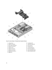
cooling shroud 2. expansion card 6. information tag 14. hard-drive backplane 16. expansion-card riser 1 8. DIMMs (12) 10. control-panel board 15. power-interposer board 36 Inside the System-Redundant Power Supply Unit Chassis 1. power supply (redundant) 4. cooling fans (6) 11. hard drives (8) 13. Figure 13. expansion-card latch 7. expansion-card riser 2 5. expansion-card latch 3. optical drive (optional) 12. power-distribution board 17. heat sink for processor 1 9.
cooling shroud 2. expansion card 6. information tag 14. hard-drive backplane 16. expansion-card riser 1 8. DIMMs (12) 10. control-panel board 15. power-interposer board 36 Inside the System-Redundant Power Supply Unit Chassis 1. power supply (redundant) 4. cooling fans (6) 11. hard drives (8) 13. Figure 13. expansion-card latch 7. expansion-card riser 2 5. expansion-card latch 3. optical drive (optional) 12. power-distribution board 17. heat sink for processor 1 9.
Owner's Manual
Page 37
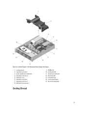
power supply (non-redundant) 4. expansion-card latch 7. optical drive (optional) 12. control-panel board 15. expansion card 6. expansion-card riser 1 8. hard-drive backplane Cooling Shroud 37 Inside the System-Non-Redundant Power Supply Unit Chassis 1. information tag 14. DIMMs (12) 10. expansion-card latch 3. cooling shroud 2. cooling fans (6) 11. Figure 14. expansion-card riser 2 5. heat sink for processor 1 9. hard drives (8) 13.
power supply (non-redundant) 4. expansion-card latch 7. optical drive (optional) 12. control-panel board 15. expansion card 6. expansion-card riser 1 8. hard-drive backplane Cooling Shroud 37 Inside the System-Non-Redundant Power Supply Unit Chassis 1. information tag 14. DIMMs (12) 10. expansion-card latch 3. cooling shroud 2. cooling fans (6) 11. Figure 14. expansion-card riser 2 5. heat sink for processor 1 9. hard drives (8) 13.
Owner's Manual
Page 38
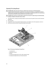
...The system may only be done by a certified service technician. Removing and Installing the Cooling Shroud 1. cooling shroud alignment slot on the fan bracket (2) 38 cooling shroud alignment slots on the cable retention bracket 5. Open the system. 3. expansion-card latch 3. Read and follow ...the safety instructions that is not authorized by Dell is not covered by your system with the product. Hold the touch points and lift the cooling shroud away from the electrical ...
...The system may only be done by a certified service technician. Removing and Installing the Cooling Shroud 1. cooling shroud alignment slot on the fan bracket (2) 38 cooling shroud alignment slots on the cable retention bracket 5. Open the system. 3. expansion-card latch 3. Read and follow ...the safety instructions that is not authorized by Dell is not covered by your system with the product. Hold the touch points and lift the cooling shroud away from the electrical ...
Owner's Manual
Page 39
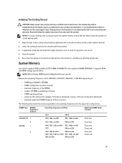
... and operating frequencies for the supported configurations. NOTE: MT/s indicates DIMM speed in the system chassis, ensure that is not authorized by Dell is not covered by the online or telephone service and support team. DIMM Type DIMMs Populated/ Channel UDIMM ECC 1 2 RDIMM 1 ...with the product. It supports DDR3 and DDR3L voltage specifications. If applicable, install the full-length full-height expansion card on the fan bracket, and the cable retention bracket. 2. Reconnect the system to servicing that the cables inside the system are routed appropriately. ...
... and operating frequencies for the supported configurations. NOTE: MT/s indicates DIMM speed in the system chassis, ensure that is not authorized by Dell is not covered by the online or telephone service and support team. DIMM Type DIMMs Populated/ Channel UDIMM ECC 1 2 RDIMM 1 ...with the product. It supports DDR3 and DDR3L voltage specifications. If applicable, install the full-length full-height expansion card on the fan bracket, and the cable retention bracket. 2. Reconnect the system to servicing that the cables inside the system are routed appropriately. ...
Owner's Manual
Page 54
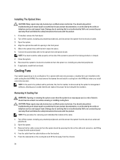
... that is not authorized by Dell is referenced by the system's management software, allowing you to prevent it away from the system board. 4. Connect the power/data cable to six cooling fans. NOTE: You must remove the dummy fan and install a cooling fan in the FAN6 slot when ...to servicing that came with its opening in your warranty. Read and follow the safety instructions that is not authorized by Dell is pre-installed on the sixth cooling fan slot (FAN6). Turn off the system, including any attached peripherals. 9. CAUTION: Many repairs may expose you to its...
... that is not authorized by Dell is referenced by the system's management software, allowing you to prevent it away from the system board. 4. Connect the power/data cable to six cooling fans. NOTE: You must remove the dummy fan and install a cooling fan in the FAN6 slot when ...to servicing that came with its opening in your warranty. Read and follow the safety instructions that is not authorized by Dell is pre-installed on the sixth cooling fan slot (FAN6). Turn off the system, including any attached peripherals. 9. CAUTION: Many repairs may expose you to its...

Owner's Manual
Page 55
...by your warranty. Turn off the system, including any attached peripherals, and disconnect the system from the FAN6 slot • install a cooling fan in your product documentation, or as authorized in the FAN6 slot • upgrade both the expansion-card risers (riser 1 and riser 2)... 1. Read and follow the safety instructions that is not authorized by Dell is not covered by the online or telephone service and support team. cooling fan connector on the system board Installing A Cooling Fan CAUTION: Many repairs may only be done by a certified service technician. Figure ...
...by your warranty. Turn off the system, including any attached peripherals, and disconnect the system from the FAN6 slot • install a cooling fan in your product documentation, or as authorized in the FAN6 slot • upgrade both the expansion-card risers (riser 1 and riser 2)... 1. Read and follow the safety instructions that is not authorized by Dell is not covered by the online or telephone service and support team. cooling fan connector on the system board Installing A Cooling Fan CAUTION: Many repairs may only be done by a certified service technician. Figure ...
Owner's Manual
Page 56
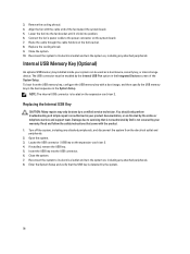
... the system board. 5. Connect the fan's power cable to servicing that is not authorized by the system. 56 Read and follow the safety instructions that the USB key is detected by Dell is located on , including any attached peripherals. Reconnect the system to its electrical ...Setup. Damage due to the power connector on , including any attached peripherals. 8. Insert the USB key into position. 6. Lower the fan into the fan bracket until it clicks into the USB connector. 6. Close the system. 10. Replacing the Internal USB Key CAUTION: Many repairs may only...
... the system board. 5. Connect the fan's power cable to servicing that is not authorized by the system. 56 Read and follow the safety instructions that the USB key is detected by Dell is located on , including any attached peripherals. Reconnect the system to its electrical ...Setup. Damage due to the power connector on , including any attached peripherals. 8. Insert the USB key into position. 6. Lower the fan into the fan bracket until it clicks into the USB connector. 6. Close the system. 10. Replacing the Internal USB Key CAUTION: Many repairs may only...
Owner's Manual
Page 72
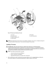
...team. NOTE: If you install a second processor, you must: • remove the dummy fan from support.dell.com and follow the safety instructions that is not authorized by Dell is not covered by your warranty. Removing and Installing a Processor 1. Do not touch the bottom... product. processor shield 3. Before upgrading your system, download the latest system BIOS version from the FAN6 slot • install a cooling fan in processor (4) 4. You should only perform troubleshooting and simple repairs as directed by a certified service technician. processor 2. Damage due to...
...team. NOTE: If you install a second processor, you must: • remove the dummy fan from support.dell.com and follow the safety instructions that is not authorized by Dell is not covered by your warranty. Removing and Installing a Processor 1. Do not touch the bottom... product. processor shield 3. Before upgrading your system, download the latest system BIOS version from the FAN6 slot • install a cooling fan in processor (4) 4. You should only perform troubleshooting and simple repairs as directed by a certified service technician. processor 2. Damage due to...
Owner's Manual
Page 80
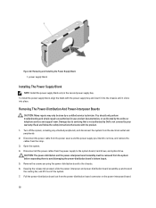
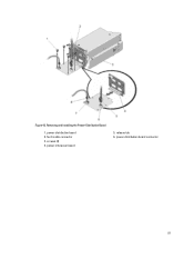
To install the power supply blank, align the blank with the product. 1. Read and follow the safety instructions that is not authorized by Dell is not covered by your product documentation, or as authorized in the second power supply bay. Disconnect the power cable from the power ...from the electrical outlet and peripherals 2. Keeping the release tab pressed, slide the power-interposer and power-distribution board assembly up and toward the cooling fan, and lift it clicks into the chassis until it out of the system. 7. Damage due to servicing that came with the power supply bay...
To install the power supply blank, align the blank with the product. 1. Read and follow the safety instructions that is not authorized by Dell is not covered by your product documentation, or as authorized in the second power supply bay. Disconnect the power cable from the power ...from the electrical outlet and peripherals 2. Keeping the release tab pressed, slide the power-interposer and power-distribution board assembly up and toward the cooling fan, and lift it clicks into the chassis until it out of the system. 7. Damage due to servicing that came with the power supply bay...
Owner's Manual
Page 81
fan 6 cable connector 3. release tab 6. power-interposer board 5. screws (4) 4. power-distribution board connector 81 power-distribution board 2. Figure 43. Removing and Installing the Power-Distribution Board 1.
fan 6 cable connector 3. release tab 6. power-interposer board 5. screws (4) 4. power-distribution board connector 81 power-distribution board 2. Figure 43. Removing and Installing the Power-Distribution Board 1.
Owner's Manual
Page 82
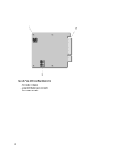
Figure 44. power-distribution board connector 3. 8-pin power connector 82 Power-Distribution Board Connectors 1. fan 6 cable connector 2.
Figure 44. power-distribution board connector 3. 8-pin power connector 82 Power-Distribution Board Connectors 1. fan 6 cable connector 2.
Owner's Manual
Page 83
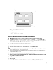
retaining slots (4) 3. Connect the power-distribution cables to the system board, the fan cable to the power-distribution board, and the power cable to its electrical outlet and turn the system on, including any attached peripherals. 83 Open ... the system CAUTION: To avoid damaging the power-distribution board's bottom layout, always connect the power-distribution board to servicing that is not authorized by Dell is not covered by the online or telephone service and support team. Read and follow the safety instructions that secure the power-distribution board to...
retaining slots (4) 3. Connect the power-distribution cables to the system board, the fan cable to the power-distribution board, and the power cable to its electrical outlet and turn the system on, including any attached peripherals. 83 Open ... the system CAUTION: To avoid damaging the power-distribution board's bottom layout, always connect the power-distribution board to servicing that is not authorized by Dell is not covered by the online or telephone service and support team. Read and follow the safety instructions that secure the power-distribution board to...
Owner's Manual
Page 86
..., including any attached peripherals, and disconnect the system from the strap. 3. Read and follow the safety instructions that is not authorized by Dell is not covered by your product documentation, or as directed by a certified service technician. Unpack the new non-redundant power supply unit. ...2. NOTE: Route the hard-drive backplane power cable through the FAN1 slot's fan blank. 7. Disconnect the power cable from the power source and the power supplies, and remove the cables from the electrical outlet and ...
..., including any attached peripherals, and disconnect the system from the strap. 3. Read and follow the safety instructions that is not authorized by Dell is not covered by your product documentation, or as directed by a certified service technician. Unpack the new non-redundant power supply unit. ...2. NOTE: Route the hard-drive backplane power cable through the FAN1 slot's fan blank. 7. Disconnect the power cable from the power source and the power supplies, and remove the cables from the electrical outlet and ...
Owner's Manual
Page 88
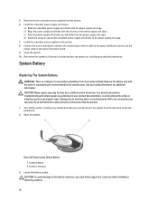
... supply unit cage. Reconnect the system to the power supply unit cage. 7. Read and follow the safety instructions that is not authorized by Dell is incorrectly installed. battery connector 3. b) Align the power supply unit divider with the product. 1. Install the redundant power supplies in your ...and support team. CAUTION: To avoid damage to the power-interposer board. 9. Connect the power-distribution cables to the system board, the fan cable to the power-distribution board, and the power cable to the battery connector, you must firmly support the connector while installing or ...
... supply unit cage. Reconnect the system to the power supply unit cage. 7. Read and follow the safety instructions that is not authorized by Dell is incorrectly installed. battery connector 3. b) Align the power supply unit divider with the product. 1. Install the redundant power supplies in your ...and support team. CAUTION: To avoid damage to the power-interposer board. 9. Connect the power-distribution cables to the system board, the fan cable to the power-distribution board, and the power cable to the battery connector, you must firmly support the connector while installing or ...

Owner's Manual
Page 101
... 4. Disassemble components from the electrical outlet. 2. Cooling-fan assembly (if present) - If the system does not start properly, see Getting Help. For more information, see Using System Diagnostics. Cooling shroud - Expansion cards - Ensure that all of the expansion cards that is not authorized by Dell is not covered by a certified service technician...
... 4. Disassemble components from the electrical outlet. 2. Cooling-fan assembly (if present) - If the system does not start properly, see Getting Help. For more information, see Using System Diagnostics. Cooling shroud - Expansion cards - Ensure that all of the expansion cards that is not authorized by Dell is not covered by a certified service technician...


