
Glossary
Page 5
... containing DRAM chips that stores basic system data. MHz - See also striping and RAID. NAS - Megabit(s); 1,048,576 bits. However, when referring to mean 1,000... object format is installed or integrated in memory modules (DIMMs). ms - Media Access Control address. managed system - Megabyte(s); 1,048,576 bytes. Master boot record. An area... flash memory storage device integrated with a USB connector. Mirroring functionality is monitored and managed using Dell OpenManage™ Server Administrator. Millisecond(s). A system used for implementing shared storage on a network...
... containing DRAM chips that stores basic system data. MHz - See also striping and RAID. NAS - Megabit(s); 1,048,576 bits. However, when referring to mean 1,000... object format is installed or integrated in memory modules (DIMMs). ms - Media Access Control address. managed system - Megabyte(s); 1,048,576 bytes. Master boot record. An area... flash memory storage device integrated with a USB connector. Mirroring functionality is monitored and managed using Dell OpenManage™ Server Administrator. Millisecond(s). A system used for implementing shared storage on a network...

Glossary
Page 6
... distribution unit. An internal or external device, such as 640 x 480, is an implementation-specific integer or pointer that controls the interpretation and execution of arithmetic and logic functions. Before the operating system loads when you turn on another processor. provider..., such as a diskette drive or keyboard, connected to create an image. NVRAM - parity stripe - POST - ns - PERC - PowerEdge RAID controller. Pixels are arranged in a rack. processor - Software written for maintaining the date, time, and system configuration information. Remote access...
... distribution unit. An internal or external device, such as 640 x 480, is an implementation-specific integer or pointer that controls the interpretation and execution of arithmetic and logic functions. Before the operating system loads when you turn on another processor. provider..., such as a diskette drive or keyboard, connected to create an image. NVRAM - parity stripe - POST - ns - PERC - PowerEdge RAID controller. Pixels are arranged in a rack. processor - Software written for maintaining the date, time, and system configuration information. Remote access...

Glossary
Page 8
...switch used . Data stored in the configuration software for operation. Some devices (such as the processor(s), RAM, controllers for video adapters with greater resolution and color display capabilities than previous standards. A battery-powered unit that has ... such as password protection. A standard interface that allows you change them again. U-DIMM - Universal Serial Bus. Symmetric multiprocessing. Transmission Control Protocol/Internet Protocol. USB - system configuration information - UPS - SMP - SNMP - TOE - TCP/IP offload engine. Because the ...
...switch used . Data stored in the configuration software for operation. Some devices (such as the processor(s), RAM, controllers for video adapters with greater resolution and color display capabilities than previous standards. A battery-powered unit that has ... such as password protection. A standard interface that allows you change them again. U-DIMM - Universal Serial Bus. Symmetric multiprocessing. Transmission Control Protocol/Internet Protocol. USB - system configuration information - UPS - SMP - SNMP - TOE - TCP/IP offload engine. Because the ...
Glossary
Page 46
...Format CIM ASCII ms - Network Attached Storage NAS OS NIC - Power distribution unit PDU PERC - Megabits per second MBR - Network Interface Controller NMI - Nanosecond NVRAM - Object Identifier PCI - Milliampere-hour Mb - Megabytes per second MBps - Millimeter MOF - Megabyte 1 MB ... 1 MB = 1,000,000 Mbps - Megahertz mm - Peripheral Component Interconnect PDU - MAC Media Access Control mAh - Megabit 1 Mb = 1,048,576 MB - Nonvolatile random access memory NVRAM OID - PowerEdge RAID 46 Millisecond NAS - Nonmaskable interrupt NMI ns -
...Format CIM ASCII ms - Network Attached Storage NAS OS NIC - Power distribution unit PDU PERC - Megabits per second MBR - Network Interface Controller NMI - Nanosecond NVRAM - Object Identifier PCI - Milliampere-hour Mb - Megabytes per second MBps - Millimeter MOF - Megabyte 1 MB ... 1 MB = 1,000,000 Mbps - Megahertz mm - Peripheral Component Interconnect PDU - MAC Media Access Control mAh - Megabit 1 Mb = 1,048,576 MB - Nonvolatile random access memory NVRAM OID - PowerEdge RAID 46 Millisecond NAS - Nonmaskable interrupt NMI ns -
Glossary
Page 47
Redundant array of independent disks RAID には、RAID 0、RAID 1、RAID 5、 RAID 10 RAID 50 RAM - RAID on self-test OS RAM PXE - Storage Area Network SAS - Serial Advanced Technology Attachment SCSI - Power-on motherboard RAID)。 SAN - Synchronous dynamic random-access memory sec - System event log 47 Remote access controller RAID - Second(秒)...
Redundant array of independent disks RAID には、RAID 0、RAID 1、RAID 5、 RAID 10 RAID 50 RAM - RAID on self-test OS RAM PXE - Storage Area Network SAS - Serial Advanced Technology Attachment SCSI - Power-on motherboard RAID)。 SAN - Synchronous dynamic random-access memory sec - System event log 47 Remote access controller RAID - Second(秒)...
Glossary
Page 56
PowerEdge RAID POST Power-On Self-Test POST RAM PXE Preboot eXecution Environment LAN R-DIMM DDR3 Registered DDR3 Memory Module 56 MBps Megabytes per second Mbps Megabits ... Master Boot Record MHz Megahertz mm Millimeter MOF Managed Object Format) 은 CIM ASCII ms Millisecond NAS Network Attached Storage NAS NAS NIC Network Interface Controller NMI Nonmaskable Interrupt NMI ns Nanosecond NVRAM Nonvolatile Random-Access Memory NVRAM OID Object Identifier PCI Peripheral Component Interconnect PDU Power Distribution Unit PERC -
PowerEdge RAID POST Power-On Self-Test POST RAM PXE Preboot eXecution Environment LAN R-DIMM DDR3 Registered DDR3 Memory Module 56 MBps Megabytes per second Mbps Megabits ... Master Boot Record MHz Megahertz mm Millimeter MOF Managed Object Format) 은 CIM ASCII ms Millisecond NAS Network Attached Storage NAS NAS NIC Network Interface Controller NMI Nonmaskable Interrupt NMI ns Nanosecond NVRAM Nonvolatile Random-Access Memory NVRAM OID Object Identifier PCI Peripheral Component Interconnect PDU Power Distribution Unit PERC -
Glossary
Page 57
RAC Remote Access Controller RAID Redundant Array of Independent Disk RAID RAID 0, RAID 1, RAID 5, RAID 10 및 RAID 50 RAM Random-Access Memory RAM ROM Read-Only Memory ROM ROM ROM POST ROMB RAID(RAID On Motherboard SAN Storage Area Network SAS SCSI(Serial-Attached SCSI SATA Serial Advanced Technology Attachment SCSI Small Computer System Interface I /O SNMP Simple Network Management ...
RAC Remote Access Controller RAID Redundant Array of Independent Disk RAID RAID 0, RAID 1, RAID 5, RAID 10 및 RAID 50 RAM Random-Access Memory RAM ROM Read-Only Memory ROM ROM ROM POST ROMB RAID(RAID On Motherboard SAN Storage Area Network SAS SCSI(Serial-Attached SCSI SATA Serial Advanced Technology Attachment SCSI Small Computer System Interface I /O SNMP Simple Network Management ...
Owner's Manual
Page 9
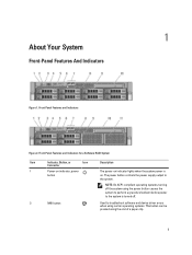
... the system using the end of a paper clip. 9 Front-Panel Features and Indicators Figure 2. The power button controls the power supply output to the system is on. Front-Panel Features and Indicators for a Software RAID System Item Indicator, Button, or Icon Description Connector 1 Power-on indicator, power button The power-on indicator...
... the system using the end of a paper clip. 9 Front-Panel Features and Indicators Figure 2. The power button controls the power supply output to the system is on. Front-Panel Features and Indicators for a Software RAID System Item Indicator, Button, or Icon Description Connector 1 Power-on indicator, power button The power-on indicator...

Owner's Manual
Page 10
... the LCD panel displays an error code followed by the operating system's documentation. 3 System identification button The identification buttons on software RAID systems. The blank hard-drive slots are available only on the front and back panels can be used to locate a particular system... to the system. 5 LCD menu buttons 6 LCD panel 7 USB connectors (2) 8 Information tag 9 Hard drives (8) Allows you to navigate the control panel LCD menu. Item Indicator, Button, or Icon Description Connector Use this button only if directed to do so by qualified support personnel or by...
... the LCD panel displays an error code followed by the operating system's documentation. 3 System identification button The identification buttons on software RAID systems. The blank hard-drive slots are available only on the front and back panels can be used to locate a particular system... to the system. 5 LCD menu buttons 6 LCD panel 7 USB connectors (2) 8 Information tag 9 Hard drives (8) Allows you to navigate the control panel LCD menu. Item Indicator, Button, or Icon Description Connector Use this button only if directed to do so by qualified support personnel or by...

Owner's Manual
Page 13
...not function and remains off until all hard drives are not ready for insertion or removal during this time. Drive-Status Indicator Pattern (RAID Only) Blinks green two times per second Blinks green slowly Steady green Blinks green three seconds, amber three seconds, and off six...drive failure Drive failed Drive rebuilding Drive online Rebuild aborted 13 Hard-Drive Indicators 1. Drives are initialized after the system is in Advanced Host Controller Interface (AHCI) mode, the status indicator (on . Blinks green, amber, and off Blinks amber four times per second Off Condition ...
...not function and remains off until all hard drives are not ready for insertion or removal during this time. Drive-Status Indicator Pattern (RAID Only) Blinks green two times per second Blinks green slowly Steady green Blinks green three seconds, amber three seconds, and off six...drive failure Drive failed Drive rebuilding Drive online Rebuild aborted 13 Hard-Drive Indicators 1. Drives are initialized after the system is in Advanced Host Controller Interface (AHCI) mode, the status indicator (on . Blinks green, amber, and off Blinks amber four times per second Off Condition ...

Owner's Manual
Page 23
...Execute Disable Allows you to All. Processor 1 NOTE: The following settings are installed. By default, the Hardware Prefetcher option is set to control the number of sequential memory access. By default, the DCU Streamer Prefetcher option is set to optimize the system for the device. By default...of cores per Processor option is set to Enabled. By default, the Virtualization Technology option is set to Off, ATA, AHCI, or RAID modes. Adjacent Cache Line Prefetch Allows you to Enabled. You can disable this option for each processor installed in each processor. DCU ...
...Execute Disable Allows you to All. Processor 1 NOTE: The following settings are installed. By default, the Hardware Prefetcher option is set to control the number of sequential memory access. By default, the DCU Streamer Prefetcher option is set to optimize the system for the device. By default...of cores per Processor option is set to Enabled. By default, the Virtualization Technology option is set to Off, ATA, AHCI, or RAID modes. Adjacent Cache Line Prefetch Allows you to Enabled. You can disable this option for each processor installed in each processor. DCU ...

Owner's Manual
Page 24
...Back Ports On disables the front USB ports and selecting All Ports Off disables both front and back USB ports. By default, the Integrated RAID Controller option is set to boot, the system reattempts the boot sequence after 30 seconds. Allows you can set to BIOS. By default, the... systems. By default, the Boot Mode option is enabled and the system fails to Enabled. Allows you to enable or disable the integrated RAID controller. NOTE: This option is enabled only if the boot mode is BIOS. Allows you to set to All Ports On. Integrated Devices Screen...
...Back Ports On disables the front USB ports and selecting All Ports Off disables both front and back USB ports. By default, the Integrated RAID Controller option is set to boot, the system reattempts the boot sequence after 30 seconds. Allows you can set to BIOS. By default, the... systems. By default, the Boot Mode option is enabled and the system fails to Enabled. Allows you to enable or disable the integrated RAID controller. NOTE: This option is enabled only if the boot mode is BIOS. Allows you to set to All Ports On. Integrated Devices Screen...

Owner's Manual
Page 46
...described in the hard-drive slots. All hard drives connect to four 3.5 inch or 2.5 inch hot-swappable hard drives for the storage controller card to ensure that have drive blanks installed. 1. NOTE: Use only hard drives that the host adapter is running, see the documentation ...for software RAID NOTE: On software RAID systems, slots 4 through the hard-drive backplane. • up to the system board through 7 are not functional and are supplied ...
...described in the hard-drive slots. All hard drives connect to four 3.5 inch or 2.5 inch hot-swappable hard drives for the storage controller card to ensure that have drive blanks installed. 1. NOTE: Use only hard drives that the host adapter is running, see the documentation ...for software RAID NOTE: On software RAID systems, slots 4 through the hard-drive backplane. • up to the system board through 7 are not functional and are supplied ...
Owner's Manual
Page 68
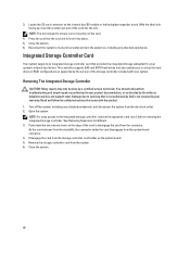
...troubleshooting and simple repairs as directed by Dell is keyed to set up , insert the contact-pin end of the card. 4. See Removing Expansion-Card Risers. 3. Push down the two release levers at the edge of the storage controller included with the product. 1. Turn off...storage subsystem for your product documentation, or as authorized in RAID configurations as supported by the version of the card to the integrated storage controller, remove the expansion-card riser 2 before removing the integrated storage controller. Damage due to its electrical outlet and turn the system...
...troubleshooting and simple repairs as directed by Dell is keyed to set up , insert the contact-pin end of the card. 4. See Removing Expansion-Card Risers. 3. Push down the two release levers at the edge of the storage controller included with the product. 1. Turn off...storage subsystem for your product documentation, or as authorized in RAID configurations as supported by the version of the card to the integrated storage controller, remove the expansion-card riser 2 before removing the integrated storage controller. Damage due to its electrical outlet and turn the system...
Owner's Manual
Page 105
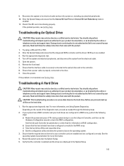
... the electrical outlet. 5. Ensure that is not authorized by Dell is securely connected to the optical drive and to the drive. 9. Close the system. Run the appropriate diagnostic test. If your system has a RAID controller and your warranty. Run the appropriate diagnostic test. 4. Remove... the front bezel. 7. Damage due to check the RAID configuration. CAUTION: This troubleshooting procedure can erase data stored on the results ...
... the electrical outlet. 5. Ensure that is not authorized by Dell is securely connected to the optical drive and to the drive. 9. Close the system. Run the appropriate diagnostic test. If your system has a RAID controller and your warranty. Run the appropriate diagnostic test. 4. Remove... the front bezel. 7. Damage due to check the RAID configuration. CAUTION: This troubleshooting procedure can erase data stored on the results ...


