Hardware Owner's Manual
Page 5
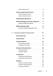
... System Password 72 Using the Setup Password 75 Embedded System Management 76 Baseboard Management Controller Configuration . . . 77 Entering the BMC Setup Module 77 iDRAC6 Configuration Utility 78 Entering the iDRAC6 Configuration Utility . . . . . 78 3 Installing System Components 79 Recommended Tools 79 Inside the System 79 Front Bezel (Optional 82 Removing the Front Bezel...
... System Password 72 Using the Setup Password 75 Embedded System Management 76 Baseboard Management Controller Configuration . . . 77 Entering the BMC Setup Module 77 iDRAC6 Configuration Utility 78 Entering the iDRAC6 Configuration Utility . . . . . 78 3 Installing System Components 79 Recommended Tools 79 Inside the System 79 Front Bezel (Optional 82 Removing the Front Bezel...

Hardware Owner's Manual
Page 7
... 119 Removing the Storage Controller Card 119 Installing the Storage Controller Card 121 iDRAC6 Express Card (Optional 122 Installing an iDRAC6 Express Card 122 Removing an iDRAC6 Express Card 123 iDRAC6 Enterprise Card (Optional 124 Installing an iDRAC6 Enterprise Card 124 Removing an iDRAC6 Enterprise Card 126 VFlash Media (Optional 127 Installing a VFlash Media Card 127...
... 119 Removing the Storage Controller Card 119 Installing the Storage Controller Card 121 iDRAC6 Express Card (Optional 122 Installing an iDRAC6 Express Card 122 Removing an iDRAC6 Express Card 123 iDRAC6 Enterprise Card (Optional 124 Installing an iDRAC6 Enterprise Card 124 Removing an iDRAC6 Enterprise Card 126 VFlash Media (Optional 127 Installing a VFlash Media Card 127...

Hardware Owner's Manual
Page 11
...your integrated NIC. Enters the utility to access utilities such as embedded system diagnostics. For more information, see the BMC or iDRAC6 user documentation. See "Using the System Setup Program and UEFI Boot Manager" on page 57. For more information, see the... For more information, see the Lifecycle Controller documentation at support.dell.com/manuals. See "Using the System Setup Program and UEFI Boot Manager" on page 57. Enters the Baseboard Management Controller (BMC) or iDRAC6 Configuration Utility, which opens the Lifecycle Controller. Enters the SAS...
...your integrated NIC. Enters the utility to access utilities such as embedded system diagnostics. For more information, see the BMC or iDRAC6 user documentation. See "Using the System Setup Program and UEFI Boot Manager" on page 57. For more information, see the... For more information, see the Lifecycle Controller documentation at support.dell.com/manuals. See "Using the System Setup Program and UEFI Boot Manager" on page 57. Enters the Baseboard Management Controller (BMC) or iDRAC6 Configuration Utility, which opens the Lifecycle Controller. Enters the SAS...
Hardware Owner's Manual
Page 14
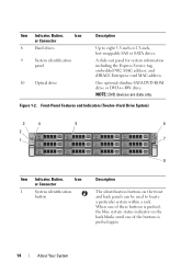
... slimline SATA DVD-ROM drive or DVD+/-RW drive. A slide-out panel for system information including the Express Service tag, embedded NIC MAC address, and iDRAC6 Enterprise card MAC address. Figure 1-2. Item Indicator, Button, Icon or Connector 8 Hard drives 9 System identification panel 10 Optical drive Description Up to locate a particular system...
... slimline SATA DVD-ROM drive or DVD+/-RW drive. A slide-out panel for system information including the Express Service tag, embedded NIC MAC address, and iDRAC6 Enterprise card MAC address. Figure 1-2. Item Indicator, Button, Icon or Connector 8 Hard drives 9 System identification panel 10 Optical drive Description Up to locate a particular system...
Hardware Owner's Manual
Page 16
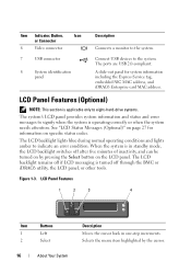
... of inactivity, and can be turned on page 27 for system information including the Express Service tag, embedded NIC MAC address, and iDRAC6 Enterprise card MAC address. The ports are USB 2.0-compliant. The LCD backlight lights blue during normal operating conditions and lights amber to ...Buttons 1 Left 2 Select 16 About Your System Description Moves the cursor back in standby mode, the LCD backlight switches off through the BMC or iDRAC6 utility, the LCD panel, or other tools. LCD Panel Features (Optional) NOTE: This section is applicable only to eight-hard-drive systems. The ...
... of inactivity, and can be turned on page 27 for system information including the Express Service tag, embedded NIC MAC address, and iDRAC6 Enterprise card MAC address. The ports are USB 2.0-compliant. The LCD backlight lights blue during normal operating conditions and lights amber to ...Buttons 1 Left 2 Select 16 About Your System Description Moves the cursor back in standby mode, the LCD backlight switches off through the BMC or iDRAC6 utility, the LCD panel, or other tools. LCD Panel Features (Optional) NOTE: This section is applicable only to eight-hard-drive systems. The ...

Hardware Owner's Manual
Page 18
... home Description Select DHCP or Static IP to match an LCD message with an SEL entry. Setup Menu Option BMC or DRAC NOTE: If an iDRAC6 Express card is installed on the LCD Home screen. Select the default information to be displayed on the system, the BMC option is replaced by...: BMC IP supports only IPv4 addresses. See "View Menu" on page 18 to display by DRAC IP. MAC Displays the MAC addresses for the optional iDRAC6. This can be selected to see the options and option items that matches the IPMI description in a format that can be useful when trying to...
... home Description Select DHCP or Static IP to match an LCD message with an SEL entry. Setup Menu Option BMC or DRAC NOTE: If an iDRAC6 Express card is installed on the LCD Home screen. Select the default information to be displayed on the system, the BMC option is replaced by...: BMC IP supports only IPv4 addresses. See "View Menu" on page 18 to display by DRAC IP. MAC Displays the MAC addresses for the optional iDRAC6. This can be selected to see the options and option items that matches the IPMI description in a format that can be useful when trying to...

Hardware Owner's Manual
Page 21
...configuration is available on the configuration, your system for more information. Connects an external SD memory card for the optional iDRAC6 Enterprise card. NOTE: See the Getting Started Guide that ships with your system may have either riser 1 or riser...indicator assembly through the optional cable management arm. About Your System 21 Item Indicator, Button, or Icon Connector 1 Serial connector 2 Video connector 3 iDRAC6 Enterprise port (optional) 4 VFlash media slot (optional) 5 USB connectors (2) 6 Ethernet connectors (2) 7 PCIe expansion card slots using riser card ...
...configuration is available on the configuration, your system for more information. Connects an external SD memory card for the optional iDRAC6 Enterprise card. NOTE: See the Getting Started Guide that ships with your system may have either riser 1 or riser...indicator assembly through the optional cable management arm. About Your System 21 Item Indicator, Button, or Icon Connector 1 Serial connector 2 Video connector 3 iDRAC6 Enterprise port (optional) 4 VFlash media slot (optional) 5 USB connectors (2) 6 Ethernet connectors (2) 7 PCIe expansion card slots using riser card ...

Hardware Owner's Manual
Page 34
... problem persists, see "Getting Help" on page 165. 34 About Your System Code E1920 E1A14 E1A15 E1A1D E2010 E2011 Text Causes Corrective Actions iDRAC6 Upgrade The iDRAC6 Express Reseat the iDRAC6 Failed Card is bad. SAS cable B failure. See "Installing Memory Modules" on page 108 or "Troubleshooting System Memory" on page 187. If...
... problem persists, see "Getting Help" on page 165. 34 About Your System Code E1920 E1A14 E1A15 E1A1D E2010 E2011 Text Causes Corrective Actions iDRAC6 Upgrade The iDRAC6 Express Reseat the iDRAC6 Failed Card is bad. SAS cable B failure. See "Installing Memory Modules" on page 108 or "Troubleshooting System Memory" on page 187. If...
Hardware Owner's Manual
Page 38
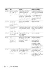
... and is full of charge left. Power cycle AC. If the problem persists, see "Troubleshooting System Memory" on DIMM ##. Check chassis cover. Information only. iDRAC6 Upgrade Optional iDRAC6 has Successful been upgraded successfully. Check PSU and config. System cover has been removed. The system configuration requires more . RAID Controller battery capacity < 24hr...
... and is full of charge left. Power cycle AC. If the problem persists, see "Troubleshooting System Memory" on DIMM ##. Check chassis cover. Information only. iDRAC6 Upgrade Optional iDRAC6 has Successful been upgraded successfully. Check PSU and config. System cover has been removed. The system configuration requires more . RAID Controller battery capacity < 24hr...

Hardware Owner's Manual
Page 40
...resulting in the table, check the documentation for the application that system may exceed PSU wattage. Rebooting. iDRAC6 not The optional iDRAC6 responding. Power required may power down without warning. that is not functioning properly or has not completed initialization. The ...and recommended action. Message Causes Corrective Actions Alert! Alert! Continuing system boot accepts the risk After AC recovery, the optional iDRAC6 takes longer than normal to the normal state. Any of these actions will reappear under the following conditions: • The...
...resulting in the table, check the documentation for the application that system may exceed PSU wattage. Rebooting. iDRAC6 not The optional iDRAC6 responding. Power required may power down without warning. that is not functioning properly or has not completed initialization. The ...and recommended action. Message Causes Corrective Actions Alert! Alert! Continuing system boot accepts the risk After AC recovery, the optional iDRAC6 takes longer than normal to the normal state. Any of these actions will reappear under the following conditions: • The...

Hardware Owner's Manual
Page 51
... CPU combination Unsupported CPU stepping detected Unsupported DIMM detected. See the to launch System Services image. See the Integrated Dell Remote Access Controller 6 (iDRAC6) User Guide for more information. Invalid memory configuration. See "General Memory Module Installation Guidelines" on page 187.... halted! See "Troubleshooting System Memory" on page 128. See "Processors" on page 165. Lifecycle Controller User The optional iDRAC6 Guide for instructions on corrupted. Enterprise card flash memory Restore the flash memory or BMC SPI flash may be using the ...
... CPU combination Unsupported CPU stepping detected Unsupported DIMM detected. See the to launch System Services image. See the Integrated Dell Remote Access Controller 6 (iDRAC6) User Guide for more information. Invalid memory configuration. See "General Memory Module Installation Guidelines" on page 187.... halted! See "Troubleshooting System Memory" on page 128. See "Processors" on page 165. Lifecycle Controller User The optional iDRAC6 Guide for instructions on corrupted. Enterprise card flash memory Restore the flash memory or BMC SPI flash may be using the ...

Hardware Owner's Manual
Page 66
... system is used for the system, to User Defined String, Model Number, or None through another LCD configuration utility (such as the optional BMC or iDRAC6 Configuration Utility or LCD panel menu). You will not be able to determine the baud rate automatically. Option Failsafe Baud Rate (115200 default) Remote Terminal...
... system is used for the system, to User Defined String, Model Number, or None through another LCD configuration utility (such as the optional BMC or iDRAC6 Configuration Utility or LCD panel menu). You will not be able to determine the baud rate automatically. Option Failsafe Baud Rate (115200 default) Remote Terminal...

Hardware Owner's Manual
Page 69
... default) restored. Exit Screen Press to 240 seconds for BMC), or User Defined. Options are Immediate (no delay), Random (between 30 to 240 seconds for iDRAC6, or 45 to exit the System Setup program; User Defined Delay Determines the user defined AC Recovery Delay. the Exit screen displays: • Save changes...
... default) restored. Exit Screen Press to 240 seconds for BMC), or User Defined. Options are Immediate (no delay), Random (between 30 to 240 seconds for iDRAC6, or 45 to exit the System Setup program; User Defined Delay Determines the user defined AC Recovery Delay. the Exit screen displays: • Save changes...

Hardware Owner's Manual
Page 76
... operating system • Running diagnostics to validate the memory, I/O devices, processors, physical disks, and other peripherals When an optional iDRAC6 Express card is an embedded utility that enables systems management tasks from an embedded environment throughout the server's lifecycle. Embedded System Management ...up the controller, configuring hardware and firmware, and deploying the operating system, see the Lifecycle Controller User Guide at support.dell.com/manuals. 76 Using the System Setup Program and UEFI Boot Manager NOTE: Certain platform configurations may not support the...
... operating system • Running diagnostics to validate the memory, I/O devices, processors, physical disks, and other peripherals When an optional iDRAC6 Express card is an embedded utility that enables systems management tasks from an embedded environment throughout the server's lifecycle. Embedded System Management ...up the controller, configuring hardware and firmware, and deploying the operating system, see the Lifecycle Controller User Guide at support.dell.com/manuals. 76 Using the System Setup Program and UEFI Boot Manager NOTE: Certain platform configurations may not support the...

Hardware Owner's Manual
Page 77
... system's operating system • Provides text console redirection for the BMC and systems management applications. Baseboard Management Controller Configuration NOTE: If an iDRAC6 Express card is replaced by the iDRAC6 utility. Entering the BMC Setup Module 1 Turn on using BMC, see the documentation for system setup, text-based utilities, and operating system...
... system's operating system • Provides text console redirection for the BMC and systems management applications. Baseboard Management Controller Configuration NOTE: If an iDRAC6 Express card is replaced by the iDRAC6 utility. Entering the BMC Setup Module 1 Turn on using BMC, see the documentation for system setup, text-based utilities, and operating system...

Hardware Owner's Manual
Page 78
... again. 78 Using the System Setup Program and UEFI Boot Manager Entering the iDRAC6 Configuration Utility 1 Turn on using iDRAC6, see the documentation for the managed server. The iDRAC6 Configuration Utility enables you press , allow the system to finish booting, restart ...your operating system begins to load before you to view and set parameters for the optional iDRAC6 and for iDRAC6 and systems management applications. iDRAC6 Configuration Utility The iDRAC6 Configuration Utility is a pre-boot configuration environment that allows you to : • Configure, enable,...
... again. 78 Using the System Setup Program and UEFI Boot Manager Entering the iDRAC6 Configuration Utility 1 Turn on using iDRAC6, see the documentation for the managed server. The iDRAC6 Configuration Utility enables you press , allow the system to finish booting, restart ...your operating system begins to load before you to view and set parameters for the optional iDRAC6 and for iDRAC6 and systems management applications. iDRAC6 Configuration Utility The iDRAC6 Configuration Utility is a pre-boot configuration environment that allows you to : • Configure, enable,...

Hardware Owner's Manual
Page 122
See Figure 6-1 for the location of the connector. 6 Press the card down until it is not covered by Dell is fully seated. Damage due to its electrical outlet and turn the system on the system board. 5 Align the front edge of the holder. 122 ... electrical outlet. 2 Open the system. See Figure 3-20. 10 Replace the expansion card. "Removing an Expansion Card" on page 115. 4 Insert the notch on the iDRAC6 Express card into the clip on , including any attached peripherals, and disconnect the system from expansion-card riser. See "Opening the System" on page 113...
See Figure 6-1 for the location of the connector. 6 Press the card down until it is not covered by Dell is fully seated. Damage due to its electrical outlet and turn the system on the system board. 5 Align the front edge of the holder. 122 ... electrical outlet. 2 Open the system. See Figure 3-20. 10 Replace the expansion card. "Removing an Expansion Card" on page 115. 4 Insert the notch on the iDRAC6 Express card into the clip on , including any attached peripherals, and disconnect the system from expansion-card riser. See "Opening the System" on page 113...

Hardware Owner's Manual
Page 123
...repairs as authorized in the expansion-card riser. See "Opening the System" on page 113. 8 Close the system. Removing an iDRAC6 Express Card CAUTION: Many repairs may only be done by the online or telephone service and support team. See "Installing an Expansion ...83. Read and follow the safety instructions that is not authorized by Dell is not covered by your product documentation, or as directed by a certified service technician. Figure 3-20. Removing and Installing an iDRAC6 Express Card 1 2 3 4 1 iDRAC6 Express card 3 notch 2 plastic standoff tab 4 clip 7 Reinstall ...
...repairs as authorized in the expansion-card riser. See "Opening the System" on page 113. 8 Close the system. Removing an iDRAC6 Express Card CAUTION: Many repairs may only be done by the online or telephone service and support team. See "Installing an Expansion ...83. Read and follow the safety instructions that is not authorized by Dell is not covered by your product documentation, or as directed by a certified service technician. Figure 3-20. Removing and Installing an iDRAC6 Express Card 1 2 3 4 1 iDRAC6 Express card 3 notch 2 plastic standoff tab 4 clip 7 Reinstall ...

Hardware Owner's Manual
Page 124
... Align the front edge of the card with the product. 1 Turn off the retention standoff. iDRAC6 Enterprise Card (Optional) Installing an iDRAC6 Enterprise Card CAUTION: Many repairs may only be done by Dell is fully seated, the plastic standoffs snap over the edge of the card. 124 Installing System... documentation, or as authorized in your warranty. See "Removing the Cooling Shroud" on page 86. 4 Remove the plastic filler plug of the iDRAC6 Enterprise port from the system board connector. 4 Angle the card so that is not authorized by a certified service technician. See Figure 3-20....
... Align the front edge of the card with the product. 1 Turn off the retention standoff. iDRAC6 Enterprise Card (Optional) Installing an iDRAC6 Enterprise Card CAUTION: Many repairs may only be done by Dell is fully seated, the plastic standoffs snap over the edge of the card. 124 Installing System... documentation, or as authorized in your warranty. See "Removing the Cooling Shroud" on page 86. 4 Remove the plastic filler plug of the iDRAC6 Enterprise port from the system board connector. 4 Angle the card so that is not authorized by a certified service technician. See Figure 3-20....

Hardware Owner's Manual
Page 125
Removing and Installing an iDRAC6 Enterprise Card 1 2 3 6 4 5 1 VFlash SD card 3 iDRAC6 Enterprise card 5 retention standoff tabs (2) 2 VFlash media slot 4 retention standoff posts (2) 6 iDRAC6 Enterprise card connector 7 If applicable, install the VFlash media card. See "Closing the System" on page 85. 9 Reconnect the system and peripherals to their power sources, and turn them on page 127. 8 Close the system. Installing System Components 125 See "Installing a VFlash Media Card" on . Figure 3-21.
Removing and Installing an iDRAC6 Enterprise Card 1 2 3 6 4 5 1 VFlash SD card 3 iDRAC6 Enterprise card 5 retention standoff tabs (2) 2 VFlash media slot 4 retention standoff posts (2) 6 iDRAC6 Enterprise card connector 7 If applicable, install the VFlash media card. See "Closing the System" on page 85. 9 Reconnect the system and peripherals to their power sources, and turn them on page 127. 8 Close the system. Installing System Components 125 See "Installing a VFlash Media Card" on . Figure 3-21.

