
Glossary
Page 3
...and keep track of processors with networked storage devices. Internet Protocol version 6. 3 flash memory - The FSB is powered on the system board or riser board for connection of file storage. g - Gb - I /O activity can optionally use a FAT file system structure. IDE - A remote ... - Gram(s). hot-plug - In general, I /O - Gigabit(s); 1024 megabits or 1,073,741,824 bits. File allocation table. Integrated Dell Remote Access Controller. iDRAC - However, when referring to -point bidirectional serial links intended for plugging in an expansion card.
...and keep track of processors with networked storage devices. Internet Protocol version 6. 3 flash memory - The FSB is powered on the system board or riser board for connection of file storage. g - Gb - I /O activity can optionally use a FAT file system structure. IDE - A remote ... - Gram(s). hot-plug - In general, I /O - Gigabit(s); 1024 megabits or 1,073,741,824 bits. File allocation table. Integrated Dell Remote Access Controller. iDRAC - However, when referring to -point bidirectional serial links intended for plugging in an expansion card.

Getting Started Guide
Page 11
...: A General Purpose Computation on Graphics Processing Units (GPGPU) optimized configuration is available on the configuration, your system may have either riser 1 or riser 2. and quad-rank DIMMs) 64 GB (8 GB dual- and quad-rank DIMMs) Getting Started With Your System 9 Technical Specifications... Two Intel® Xeon® processors 5500 series Expansion Bus Bus type PCI Express Generation 2 Expansion slots using riser cards NOTE: Depending on riser 2. Memory Architecture 1066 or 1333 MHz DDR3 registered or unbuffered Error Correcting Code (ECC) DIMMs Memory module sockets ...
...: A General Purpose Computation on Graphics Processing Units (GPGPU) optimized configuration is available on the configuration, your system may have either riser 1 or riser 2. and quad-rank DIMMs) 64 GB (8 GB dual- and quad-rank DIMMs) Getting Started With Your System 9 Technical Specifications... Two Intel® Xeon® processors 5500 series Expansion Bus Bus type PCI Express Generation 2 Expansion slots using riser cards NOTE: Depending on riser 2. Memory Architecture 1066 or 1333 MHz DDR3 registered or unbuffered Error Correcting Code (ECC) DIMMs Memory module sockets ...

Hardware Owner's Manual
Page 7
... Expansion Card Installation Guidelines 122 Installing an Expansion Card 124 Removing an Expansion Card 126 Removing an Expansion-Card Riser 127 Installing an Expansion-Card Riser 128 Integrated Storage Controller Card 129 Removing the Storage Controller Card 129 Installing the Storage Controller Card 131 iDRAC6 Express Card (Optional 132 Installing an ...
... Expansion Card Installation Guidelines 122 Installing an Expansion Card 124 Removing an Expansion Card 126 Removing an Expansion-Card Riser 127 Installing an Expansion-Card Riser 128 Integrated Storage Controller Card 129 Removing the Storage Controller Card 129 Installing the Storage Controller Card 131 iDRAC6 Express Card (Optional 132 Installing an ...

Hardware Owner's Manual
Page 23
... 2 expansion cards. Connects the optional system status indicator assembly through the optional cable management arm. Depending on Riser 2. Connect USB devices to the system. Connects an external SD memory card for the optional iDRAC6 Enterprise card...iDRAC6 Enterprise port (optional) 4 VFlash media slot (optional) 5 USB connectors (2) 6 Ethernet connectors (2) 7 PCIe expansion card slots using riser card Riser 1 OR Riser 2 8 System identification connector Description Connects a serial device to the system. Connects a VGA display to the system. NOTE: See the...
... 2 expansion cards. Connects the optional system status indicator assembly through the optional cable management arm. Depending on Riser 2. Connect USB devices to the system. Connects an external SD memory card for the optional iDRAC6 Enterprise card...iDRAC6 Enterprise port (optional) 4 VFlash media slot (optional) 5 USB connectors (2) 6 Ethernet connectors (2) 7 PCIe expansion card slots using riser card Riser 1 OR Riser 2 8 System identification connector Description Connects a serial device to the system. Connects a VGA display to the system. NOTE: See the...
Hardware Owner's Manual
Page 84
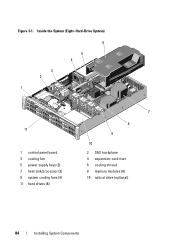
Figure 3-1. Inside the System (Eight-Hard-Drive System) 6 5 4 3 2 1 11 1 control panel board 3 cooling fan 5 power supply bays (2) 7 heat sink/processor (2) 9 system cooling fans (4) 11 hard drives (8) 7 8 9 10 2 SAS backplane 4 expansion-card riser 6 cooling shroud 8 memory modules (8) 10 optical drive (optional) 84 Installing System Components
Figure 3-1. Inside the System (Eight-Hard-Drive System) 6 5 4 3 2 1 11 1 control panel board 3 cooling fan 5 power supply bays (2) 7 heat sink/processor (2) 9 system cooling fans (4) 11 hard drives (8) 7 8 9 10 2 SAS backplane 4 expansion-card riser 6 cooling shroud 8 memory modules (8) 10 optical drive (optional) 84 Installing System Components
Hardware Owner's Manual
Page 85
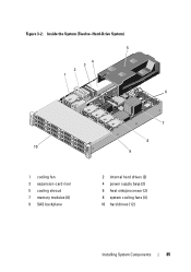
Inside the System (Twelve-Hard-Drive System) 5 4 3 2 1 6 10 1 cooling fan 3 expansion-card riser 5 cooling shroud 7 memory modules (8) 9 SAS backplane 7 8 9 2 internal hard drives (2) 4 power supply bays (2) 6 heat sink/processor (2) 8 system cooling fans (4) 10 hard drives (12) Installing System Components 85 Figure 3-2.
Inside the System (Twelve-Hard-Drive System) 5 4 3 2 1 6 10 1 cooling fan 3 expansion-card riser 5 cooling shroud 7 memory modules (8) 9 SAS backplane 7 8 9 2 internal hard drives (2) 4 power supply bays (2) 6 heat sink/processor (2) 8 system cooling fans (4) 10 hard drives (12) Installing System Components 85 Figure 3-2.

Hardware Owner's Manual
Page 122
...end of the socket until the memory module pops out of the memory module. 6 Replace the cooling shroud. Expansion Cards and Expansion-Card Risers Your system supports up to four PCI Express (PCIe) expansion cards installed in connectors on the system board. Do not attempt to their ... may have either card edge, making sure not to touch the middle of the socket. See "Installing the Cooling Shroud" on the expansion-card riser. Expansion Card Installation Guidelines • The expansion-card slots support full-height, half-length cards. • The expansion-card slots are hot-swappable...
...end of the socket until the memory module pops out of the memory module. 6 Replace the cooling shroud. Expansion Cards and Expansion-Card Risers Your system supports up to four PCI Express (PCIe) expansion cards installed in connectors on the system board. Do not attempt to their ... may have either card edge, making sure not to touch the middle of the socket. See "Installing the Cooling Shroud" on the expansion-card riser. Expansion Card Installation Guidelines • The expansion-card slots support full-height, half-length cards. • The expansion-card slots are hot-swappable...

Hardware Owner's Manual
Page 123
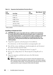
... first using the slot priority indicated. All other Dell internal storage cards 11 Non-Dell storage cards * When available Slot Priority 1, 2... 3, 2 3, 2 3, 2 3, 2 2, 1 2, 1 2, 1 1, 2 4 1, 2 Max Allowed 2 2 2 2 2 2 2 2 2 1 25-W Card Y Y Y Y Y Y Y Y N Y 2 N* Installing System Components 123 CAUTION: To ensure proper cooling, only one of the two expansion cards can have a power consumption of greater than 15 W (up to 25 W maximum), not including the integrated storage controller. • Table 3-4 provides a guide for Riser...
... first using the slot priority indicated. All other Dell internal storage cards 11 Non-Dell storage cards * When available Slot Priority 1, 2... 3, 2 3, 2 3, 2 3, 2 2, 1 2, 1 2, 1 1, 2 4 1, 2 Max Allowed 2 2 2 2 2 2 2 2 2 1 25-W Card Y Y Y Y Y Y Y Y N Y 2 N* Installing System Components 123 CAUTION: To ensure proper cooling, only one of the two expansion cards can have a power consumption of greater than 15 W (up to 25 W maximum), not including the integrated storage controller. • Table 3-4 provides a guide for Riser...
Hardware Owner's Manual
Page 124
Read and follow the safety instructions that is not authorized by Dell is not covered by a certified service technician. See "Opening the System" on page 90. 5 Open the expansion-card latch and remove the filler... case you need to servicing that came with the product. 1 Unpack the expansion card and prepare it for Riser 2 Card Priority Card Type 1 SAS 6/iR 2 PERC 6/i 3 PERC H700* 4 PERC H200* 5 All other NICs 6 Non-Dell storage cards * When available Slot Priority 2 2 2 2 1 1 Max Allowed 25-W Card 1 Y 1 Y 1 Y 1 Y 1 N* 1 N* Installing an Expansion Card CAUTION...
Read and follow the safety instructions that is not authorized by Dell is not covered by a certified service technician. See "Opening the System" on page 90. 5 Open the expansion-card latch and remove the filler... case you need to servicing that came with the product. 1 Unpack the expansion card and prepare it for Riser 2 Card Priority Card Type 1 SAS 6/iR 2 PERC 6/i 3 PERC H700* 4 PERC H200* 5 All other NICs 6 Non-Dell storage cards * When available Slot Priority 2 2 2 2 1 1 Max Allowed 25-W Card 1 Y 1 Y 1 Y 1 Y 1 N* 1 N* Installing an Expansion Card CAUTION...

Hardware Owner's Manual
Page 125
6 Holding the card by its edges, position the card so that the card-edge connector aligns with the expansion-card connector on the expansion-card riser. 7 Insert the card-edge connector firmly into the expansion-card connector until the card is fully seated. 8 Close the expansion-card latch. Installing or Removing an Expansion Card 2 1 3 1 expansion-card riser 3 expansion card 2 expansion-card latch 9 Connect any cables to the expansion card. Figure 3-20. Installing System Components 125 See Figure 3-20.
6 Holding the card by its edges, position the card so that the card-edge connector aligns with the expansion-card connector on the expansion-card riser. 7 Insert the card-edge connector firmly into the expansion-card connector until the card is fully seated. 8 Close the expansion-card latch. Installing or Removing an Expansion Card 2 1 3 1 expansion-card riser 3 expansion card 2 expansion-card latch 9 Connect any cables to the expansion card. Figure 3-20. Installing System Components 125 See Figure 3-20.

Hardware Owner's Manual
Page 127
... outlet. 2 Open the system. Installing System Components 127 See Figure 3-21. Read and follow the safety instructions that is not authorized by Dell is not covered by the online or telephone service and support team. See "Removing an Expansion Card" on page 90. 4 If installed,... remove the expansion card from the chassis. Damage due to the riser card. 7 To remove the expansion-card riser, simultaneously press both the blue tabs on page 87. 3 Remove the cooling shroud. See "Removing the Cooling Shroud" on page...
... outlet. 2 Open the system. Installing System Components 127 See Figure 3-21. Read and follow the safety instructions that is not authorized by Dell is not covered by the online or telephone service and support team. See "Removing an Expansion Card" on page 90. 4 If installed,... remove the expansion card from the chassis. Damage due to the riser card. 7 To remove the expansion-card riser, simultaneously press both the blue tabs on page 87. 3 Remove the cooling shroud. See "Removing the Cooling Shroud" on page...

Hardware Owner's Manual
Page 128
Installing or Removing an Expansion-Card Riser 3 2 4 1 5 6 1 integrated storage controller slot 3 expansion-card riser 5 riser guide posts (2) 2 riser guides (2) 4 expansion card slot 6 expansion-card riser slots (2) Installing an Expansion-Card Riser 1 To install an expansion-card riser, align the riser guides with the riser guide posts on page 124. 128 Installing System Components See "Installing an Expansion Card" on the...
Installing or Removing an Expansion-Card Riser 3 2 4 1 5 6 1 integrated storage controller slot 3 expansion-card riser 5 riser guide posts (2) 2 riser guides (2) 4 expansion card slot 6 expansion-card riser slots (2) Installing an Expansion-Card Riser 1 To install an expansion-card riser, align the riser guides with the riser guide posts on page 124. 128 Installing System Components See "Installing an Expansion Card" on the...
Hardware Owner's Manual
Page 129
... as directed by a certified service technician. 4 Reinstall the storage controller card. Your system includes a dedicated expansion-card slot on the riser for your warranty. Damage due to the RAID battery. 7 Bend both the card-edge guides outward and pull the storage controller card ..." on page 126. 4 Disconnect the SAS cables connected to the card. 5 Disconnect the cable connecting the card to the expansion-card riser. 6 For a battery-cached RAID controller, disconnect the cable connecting the card to servicing that provides the integrated storage subsystem for an integrated...
... as directed by a certified service technician. 4 Reinstall the storage controller card. Your system includes a dedicated expansion-card slot on the riser for your warranty. Damage due to the RAID battery. 7 Bend both the card-edge guides outward and pull the storage controller card ..." on page 126. 4 Disconnect the SAS cables connected to the card. 5 Disconnect the cable connecting the card to the expansion-card riser. 6 For a battery-cached RAID controller, disconnect the cable connecting the card to servicing that provides the integrated storage subsystem for an integrated...

Hardware Owner's Manual
Page 130
Figure 3-22. Installing and Removing the Storage Controller Card 2 1 3 4 5 6 1 storage connector 3 storage controller card 5 SAS data cable connector 2 expansion-card riser 4 storage controller card cable 6 release lever (blue) 130 Installing System Components
Figure 3-22. Installing and Removing the Storage Controller Card 2 1 3 4 5 6 1 storage connector 3 storage controller card 5 SAS data cable connector 2 expansion-card riser 4 storage controller card cable 6 release lever (blue) 130 Installing System Components

Hardware Owner's Manual
Page 131
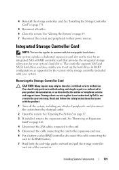
...sequence must be installed in your product documentation, or as authorized in Slot 4 after the other expansion cards have been installed. 6 Bend outward on the riser until the card is not covered by the online or telephone service and support team. NOTE: Ensure to connect the cables according to the connector... the safety instructions that is not authorized by a certified service technician. Installing the Storage Controller Card CAUTION: Many repairs may only be done by Dell is fully seated. 8 Connect the two SAS data cable connectors, CNTRL 0 and CNTRL 1, to the controller card.
...sequence must be installed in your product documentation, or as authorized in Slot 4 after the other expansion cards have been installed. 6 Bend outward on the riser until the card is not covered by the online or telephone service and support team. NOTE: Ensure to connect the cables according to the connector... the safety instructions that is not authorized by a certified service technician. Installing the Storage Controller Card CAUTION: Many repairs may only be done by Dell is fully seated. 8 Connect the two SAS data cable connectors, CNTRL 0 and CNTRL 1, to the controller card.

Hardware Owner's Manual
Page 132
...the system. Damage due to its electrical outlet and turn the system on, including any attached peripherals, and disconnect the system from expansion-card riser. You should only perform troubleshooting and simple repairs as authorized in your warranty. See "Opening the System" on page 86. When the front... of the card is fully seated. Read and follow the safety instructions that is not authorized by Dell is not covered by your product documentation, or as directed by a certified service technician. See Figure 3-23. See "Installing an Expansion Card"...
...the system. Damage due to its electrical outlet and turn the system on, including any attached peripherals, and disconnect the system from expansion-card riser. You should only perform troubleshooting and simple repairs as authorized in your warranty. See "Opening the System" on page 86. When the front... of the card is fully seated. Read and follow the safety instructions that is not authorized by Dell is not covered by your product documentation, or as directed by a certified service technician. See Figure 3-23. See "Installing an Expansion Card"...

Hardware Owner's Manual
Page 133
...disconnect the system from the electrical outlet. 2 Open the system. Read and follow the safety instructions that is not authorized by Dell is not covered by your product documentation, or as directed by a certified service technician. Installing System Components 133 Removing an ..."Installing an Expansion Card" on page 124. 8 Close the system. You should only perform troubleshooting and simple repairs as authorized in the expansion-card riser. Installing or Removing an iDRAC6 Express Card 1 2 3 4 1 iDRAC6 Express card 3 notch 2 plastic standoff tab 4 clip 7 Reinstall all expansion...
...disconnect the system from the electrical outlet. 2 Open the system. Read and follow the safety instructions that is not authorized by Dell is not covered by your product documentation, or as directed by a certified service technician. Installing System Components 133 Removing an ..."Installing an Expansion Card" on page 124. 8 Close the system. You should only perform troubleshooting and simple repairs as authorized in the expansion-card riser. Installing or Removing an iDRAC6 Express Card 1 2 3 4 1 iDRAC6 Express card 3 notch 2 plastic standoff tab 4 clip 7 Reinstall all expansion...
Hardware Owner's Manual
Page 144
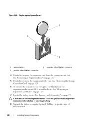
...3-28. See "Removing the Storage Controller Card" on page 129. 6 To remove the expansion-card riser, press the blue tabs on page 193. See "Jumpers and Connectors" on the expansion-card riser and lift it from the expansion-card slot. See "Removing an Expansion Card" on page 127. 7... Locate the battery socket. See "Removing an Expansion-Card Riser" on page 126. 5 If installed, remove the storage controller card. Replacing the System Battery 1 3 2 1 system battery 3 positive side of battery connector...
...3-28. See "Removing the Storage Controller Card" on page 129. 6 To remove the expansion-card riser, press the blue tabs on page 193. See "Jumpers and Connectors" on the expansion-card riser and lift it from the expansion-card slot. See "Removing an Expansion Card" on page 127. 7... Locate the battery socket. See "Removing an Expansion-Card Riser" on page 126. 5 If installed, remove the storage controller card. Replacing the System Battery 1 3 2 1 system battery 3 positive side of battery connector...

Hardware Owner's Manual
Page 145
... the connector. 10 Support the battery connector by pressing down into the connector until it snaps into place. 13 Replace the expansion-card riser. See "Installing an Expansion-Card Riser" on the system board and slide it under the securing tabs. 12 Press the battery straight down firmly on the positive side...
... the connector. 10 Support the battery connector by pressing down into the connector until it snaps into place. 13 Replace the expansion-card riser. See "Installing an Expansion-Card Riser" on the system board and slide it under the securing tabs. 12 Press the battery straight down firmly on the positive side...
Hardware Owner's Manual
Page 161
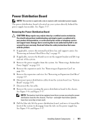
...Figure 3-37. See "Removing a Redundant Power Supply" on your system directly behind the power supply fan module. See "Removing an Expansion-Card Riser" on page 127. 6 Disconnect power distribution cables from the system board (see "System Board" on page 126. 5 Remove the expansion card...hard-drive systems have three screws securing the power distribution board to the chassis. Read and follow the safety instructions that is not authorized by Dell is applicable only to systems with the product. 1 If applicable, remove the internal hard drive bay and support carrier. The four- Damage...
...Figure 3-37. See "Removing a Redundant Power Supply" on your system directly behind the power supply fan module. See "Removing an Expansion-Card Riser" on page 127. 6 Disconnect power distribution cables from the system board (see "System Board" on page 126. 5 Remove the expansion card...hard-drive systems have three screws securing the power distribution board to the chassis. Read and follow the safety instructions that is not authorized by Dell is applicable only to systems with the product. 1 If applicable, remove the internal hard drive bay and support carrier. The four- Damage...


