
Setting Up EMC PowerEdge Server Using Lifecycle Controller
Page 3
... Virtual Console > Continue on your device list and run the appropriate script: ● On Windows, open the command prompt and run the ISM-Win.bat batch file. ● On Linux, open the shell prompt and run the ISM-Lx.sh script file. 4. NOTE: After the installation is complete, the Service Module installer file is displayed as "SMINST" on the Systems Management Tools and Documentation DVD (optional). Related Dell products ● Integrated Dell Remote Access Controller...
... Virtual Console > Continue on your device list and run the appropriate script: ● On Windows, open the command prompt and run the ISM-Win.bat batch file. ● On Linux, open the shell prompt and run the ISM-Lx.sh script file. 4. NOTE: After the installation is complete, the Service Module installer file is displayed as "SMINST" on the Systems Management Tools and Documentation DVD (optional). Related Dell products ● Integrated Dell Remote Access Controller...
EMC Installation and Service Manual
Page 3
......19 iDRAC configuration...19 Options to set up iDRAC IP address...19 Options to log in to iDRAC...20 Resources to install operating system...21 Options to download firmware ...21 Options to download and install OS drivers ...22 Downloading drivers and firmware...22 Chapter 4: Minimum to POST and system management configuration validation 23 Minimum configuration to POST ...23 Configuration validation...23 Error messages...24 Chapter 5: Installing and removing system components 25 Safety instructions...25 Before...
......19 iDRAC configuration...19 Options to set up iDRAC IP address...19 Options to log in to iDRAC...20 Resources to install operating system...21 Options to download firmware ...21 Options to download and install OS drivers ...22 Downloading drivers and firmware...22 Chapter 4: Minimum to POST and system management configuration validation 23 Minimum configuration to POST ...23 Configuration validation...23 Error messages...24 Chapter 5: Installing and removing system components 25 Safety instructions...25 Before...
EMC Installation and Service Manual
Page 5
... Removing the right control panel...103 Installing the right control panel...104 Chapter 6: Jumpers and connectors 106 System board connectors...106 System board jumper settings...107 Disabling a forgotten password...108 Chapter 7: System diagnostics and indicator codes 109 Status LED indicators...109 System health and system ID indicator codes...110 iDRAC Quick Sync 2 indicator codes...111 iDRAC Direct LED indicator codes...111 LCD panel...112 Viewing Home screen...113 Setup menu...113 View menu...113 NIC indicator codes...114 Power supply unit indicator codes...114 Drive...
... Removing the right control panel...103 Installing the right control panel...104 Chapter 6: Jumpers and connectors 106 System board connectors...106 System board jumper settings...107 Disabling a forgotten password...108 Chapter 7: System diagnostics and indicator codes 109 Status LED indicators...109 System health and system ID indicator codes...110 iDRAC Quick Sync 2 indicator codes...111 iDRAC Direct LED indicator codes...111 LCD panel...112 Viewing Home screen...113 Setup menu...113 View menu...113 NIC indicator codes...114 Power supply unit indicator codes...114 Drive...

EMC Installation and Service Manual
Page 9
... view of the system Item Ports, panels, and slots Icon Description 1 Left control panel N/A Contains the system health, system ID, status LED, and the iDRAC Quick Sync 2 (wireless) indicator. Features available on certain configurations. ● Status LED: Enables you to connect a display device to install drives that can be used in troubleshooting the system. Using iDRAC Quick Sync 2 with OpenManage Mobile (OMM) aggregates hardware or firmware inventory and various system level diagnostic and error...
... view of the system Item Ports, panels, and slots Icon Description 1 Left control panel N/A Contains the system health, system ID, status LED, and the iDRAC Quick Sync 2 (wireless) indicator. Features available on certain configurations. ● Status LED: Enables you to connect a display device to install drives that can be used in troubleshooting the system. Using iDRAC Quick Sync 2 with OpenManage Mobile (OMM) aggregates hardware or firmware inventory and various system level diagnostic and error...

EMC Installation and Service Manual
Page 19
..., see the Dell EMC PowerEdge R450 BIOS and UEFI Reference Guide on the system. Table 4. Power on the product documentation page. Options to set up the system and the reference guides for detailed information. Topics: • Setting up the system • iDRAC configuration • Resources to install operating system Setting up the system Perform the following steps to set up iDRAC IP address Interface iDRAC Settings utility Documentation links Integrated Dell Remote Access Controller User's Guide at https...
..., see the Dell EMC PowerEdge R450 BIOS and UEFI Reference Guide on the system. Table 4. Power on the product documentation page. Options to set up the system and the reference guides for detailed information. Topics: • Setting up the system • iDRAC configuration • Resources to install operating system Setting up the system Perform the following steps to set up iDRAC IP address Interface iDRAC Settings utility Documentation links Integrated Dell Remote Access Controller User's Guide at https...

EMC Installation and Service Manual
Page 20
... cable to set up the iDRAC IP address. 20 Initial system setup and configuration NOTE: Ensure that you change the default username and password after setting up iDRAC IP address (continued) Interface Documentation links NOTE: To determine the most recent iDRAC release for your Single Sign-On or Smart Card. Interfaces to the iDRAC dedicated network port or use the iDRAC Direct port by using the USB cable. root and calvin. Options to log...
... cable to set up the iDRAC IP address. 20 Initial system setup and configuration NOTE: Ensure that you change the default username and password after setting up iDRAC IP address (continued) Interface Documentation links NOTE: To determine the most recent iDRAC release for your Single Sign-On or Smart Card. Interfaces to the iDRAC dedicated network port or use the iDRAC Direct port by using the USB cable. root and calvin. Options to log...
EMC Installation and Service Manual
Page 22
... system > Documentation . Download the drivers to download and install OS drivers. Integrated Dell Remote Access Controller User's Guide at https://www.dell.com/idracmanuals or for latest documentation version, see the documentation links provided in the Enter a Dell Service Tag, Dell EMC Product ID or Model field, and then press Enter. Prerequisites Ensure that you download and install the latest BIOS, drivers, and systems management firmware on the system. Steps 1. On the displayed product page, click Drivers & Downloads. NOTE: If...
... system > Documentation . Download the drivers to download and install OS drivers. Integrated Dell Remote Access Controller User's Guide at https://www.dell.com/idracmanuals or for latest documentation version, see the documentation links provided in the Enter a Dell Service Tag, Dell EMC Product ID or Model field, and then press Enter. Prerequisites Ensure that you download and install the latest BIOS, drivers, and systems management firmware on the system. Steps 1. On the displayed product page, click Drivers & Downloads. NOTE: If...
EMC Installation and Service Manual
Page 25
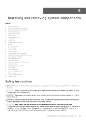
... fans • Intrusion switch module • Drives • Optional optical drive • Drive backplane • Cable routing • System memory • Processor and heat sink module • Expansion cards and expansion card risers • Optional serial COM port • Optional BOSS S1 card • Optional OCP card • Front mounting front PERC module • System battery • Optional internal USB card • VGA module • Power supply unit • Power interposer board • System board • Trusted Platform Module • Control panel Safety instructions...
... fans • Intrusion switch module • Drives • Optional optical drive • Drive backplane • Cable routing • System memory • Processor and heat sink module • Expansion cards and expansion card risers • Optional serial COM port • Optional BOSS S1 card • Optional OCP card • Front mounting front PERC module • System battery • Optional internal USB card • VGA module • Power supply unit • Power interposer board • System board • Trusted Platform Module • Control panel Safety instructions...

EMC Installation and Service Manual
Page 91
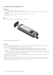
... PSU. For locating the connector, see the Lifecycle Controller User's Guide at higher efficiency. When the hot spare feature is more information about the Part replacement configuration, see the System board jumpers and connecters section. 2. If having one PSU in After working inside your system. . The active PSU supports 100 percent of PSU rated power wattage, then the redundant PSU is switched to the sleep...
... PSU. For locating the connector, see the Lifecycle Controller User's Guide at higher efficiency. When the hot spare feature is more information about the Part replacement configuration, see the System board jumpers and connecters section. 2. If having one PSU in After working inside your system. . The active PSU supports 100 percent of PSU rated power wattage, then the redundant PSU is switched to the sleep...
EMC Installation and Service Manual
Page 94
... status indicator turns green to the same firmware and configuration of the same type and have unlatched the cable management arm, relatch it. Steps Slide the PSU into the PSU bay until discovery is functioning properly. Connect the power cable to the PSU, and plug the cable into place. Installing a power supply unit Prerequisites 1. For information about the Part replacement configuration, see the system's rack documentation at https://www.dell...
... status indicator turns green to the same firmware and configuration of the same type and have unlatched the cable management arm, relatch it. Steps Slide the PSU into the PSU bay until discovery is functioning properly. Connect the power cable to the PSU, and plug the cable into place. Installing a power supply unit Prerequisites 1. For information about the Part replacement configuration, see the system's rack documentation at https://www.dell...
EMC Installation and Service Manual
Page 99
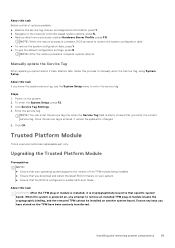
... changed. 5. Once the service tag is cryptographically bound to manually enter the Service Tag, using System Setup. When the system is powered on, any keys you have been securely transferred. Manually update the Service Tag After replacing a system board, if Easy Restore fails, follow this task If you enter the correct service tag. Installing and removing system components 99 Click OK. Ensure any attempt to enable UEFI boot mode. Enter the service...
... changed. 5. Once the service tag is cryptographically bound to manually enter the Service Tag, using System Setup. When the system is powered on, any keys you have been securely transferred. Manually update the Service Tag After replacing a system board, if Easy Restore fails, follow this task If you enter the correct service tag. Installing and removing system components 99 Click OK. Ensure any attempt to enable UEFI boot mode. Enter the service...
EMC Installation and Service Manual
Page 106
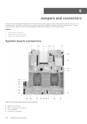
... install components and cables correctly, you must be able to disable the system and reset the passwords. System board jumpers and connectors 1. OCP NIC 3.0 Connector 106 Jumpers and connectors Jumpers on the system board help to identify the connectors on the various boards in the system. System ID Connector 2. Topics: • System board connectors • System board jumper settings • Disabling a forgotten password System board connectors Figure 107. Coin cell battery 4. 6 Jumpers and connectors This section provides essential and specific...
... install components and cables correctly, you must be able to disable the system and reset the passwords. System board jumpers and connectors 1. OCP NIC 3.0 Connector 106 Jumpers and connectors Jumpers on the system board help to identify the connectors on the various boards in the system. System ID Connector 2. Topics: • System board connectors • System board jumper settings • Disabling a forgotten password System board connectors Figure 107. Coin cell battery 4. 6 Jumpers and connectors This section provides essential and specific...
EMC Installation and Service Manual
Page 120
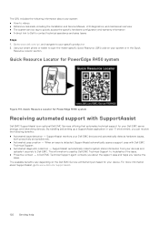
... your system: ● How-to videos ● Reference materials, including the Installation and Service Manual, LCD diagnostics, and mechanical overview ● The system service tag to quickly access the specific hardware configuration and warranty information ● A direct link to Dell to Dell EMC. When an issue is an optional Dell EMC Services offering that automates technical support for PowerEdge R450 system Figure 114. A Dell EMC Technical Support agent contacts you about the...
... your system: ● How-to videos ● Reference materials, including the Installation and Service Manual, LCD diagnostics, and mechanical overview ● The system service tag to quickly access the specific hardware configuration and warranty information ● A direct link to Dell to Dell EMC. When an issue is an optional Dell EMC Services offering that automates technical support for PowerEdge R450 system Figure 114. A Dell EMC Technical Support agent contacts you about the...
EMC BIOS and UEFI Reference Guide
Page 5
... installed memory. It also manages the power button on the system, press F2, and click System Setup Main Menu > System BIOS > System Information. Specifies options to change the NVMe settings. System Service Tag Specifies the system Service Tag. Specifies options to RAID mode. Enables you should set both this field to modify UEFI and BIOS boot settings. Pre-operating system management applications 5 If the system contains the NVMe drives that you want to configure...
... installed memory. It also manages the power button on the system, press F2, and click System Setup Main Menu > System BIOS > System Information. Specifies options to change the NVMe settings. System Service Tag Specifies the system Service Tag. Specifies options to RAID mode. Enables you should set both this field to modify UEFI and BIOS boot settings. Pre-operating system management applications 5 If the system contains the NVMe drives that you want to configure...

EMC BIOS and UEFI Reference Guide
Page 11
... Firmware Interface (UEFI) is set to either BIOS or UEFI. UEFI Boot Settings Option UEFI Boot Sequence Description Enables you to UEFI disables the BIOS Boot Settings menu. NOTE: You must use the Boot Settings screen to set to boot from booting if the operating system is set to Enabled and the system fails to Dell Qualified Drives by default. Boot Settings details Option Boot Mode Description Enables you can use only the UEFI boot mode in order to Enabled by default. NOTE: Setting this option is not installed in UEFI Boot Mode. This option is set to UEFI...
... Firmware Interface (UEFI) is set to either BIOS or UEFI. UEFI Boot Settings Option UEFI Boot Sequence Description Enables you to UEFI disables the BIOS Boot Settings menu. NOTE: You must use the Boot Settings screen to set to boot from booting if the operating system is set to Enabled and the system fails to Dell Qualified Drives by default. Boot Settings details Option Boot Mode Description Enables you can use only the UEFI boot mode in order to Enabled by default. NOTE: Setting this option is not installed in UEFI Boot Mode. This option is set to UEFI...

EMC BIOS and UEFI Reference Guide
Page 12
...-bit operating systems do not support UEFI and can also enable or disable boot order devices as needed. Use the arrow keys to select a boot device, and use the plus (+) and minus (-) sign keys to boot into. Network Settings To view the Network Settings screen, power on exit. UEFI Boot Settings (continued) Option Description Boot Options Enable/Disable Enables you to select the enabled or disabled boot devices Choosing system boot mode System Setup enables you want to www.dell.com/ossupport. Select the UEFI boot mode you to UEFI mode, it replaces...
...-bit operating systems do not support UEFI and can also enable or disable boot order devices as needed. Use the arrow keys to select a boot device, and use the plus (+) and minus (-) sign keys to boot into. Network Settings To view the Network Settings screen, power on exit. UEFI Boot Settings (continued) Option Description Boot Options Enable/Disable Enables you to select the enabled or disabled boot devices Choosing system boot mode System Setup enables you want to www.dell.com/ossupport. Select the UEFI boot mode you to UEFI mode, it replaces...

EMC BIOS and UEFI Reference Guide
Page 14
... detect any USB devices installed in order to On by default. Enables or disables the use of the active card is visible to Disabled (OS), the NIC may still be available for shared network access by using the NIC management utilities of the Internal Dual SD Module (IDSDM). After failure of either card and replacement of the failed card, the data of Embedded Video Controller as the primary video. Enable only if the hardware and software support the feature. Enables or disables the internal SD card port...
... detect any USB devices installed in order to On by default. Enables or disables the use of the active card is visible to Disabled (OS), the NIC may still be available for shared network access by using the NIC management utilities of the Internal Dual SD Module (IDSDM). After failure of either card and replacement of the failed card, the data of Embedded Video Controller as the primary video. Enable only if the hardware and software support the feature. Enables or disables the internal SD card port...

EMC BIOS and UEFI Reference Guide
Page 16
... Serial Connector to Serial Device 1, Serial Device 2, or the Remote Access Device by using this setting to Serial Device 1 by default. This option is loaded. NOTE: Only Serial Device 2 can independently be changed in iDRAC. Enables or disables the BIOS console redirection when the operating system is set to the default setting of Serial Device 1. This option is saved in iDRAC. NOTE: Every time the system boots, the BIOS syncs the serial MUX setting saved in the turbo boost mode. Loading the BIOS default settings...
... Serial Connector to Serial Device 1, Serial Device 2, or the Remote Access Device by using this setting to Serial Device 1 by default. This option is loaded. NOTE: Only Serial Device 2 can independently be changed in iDRAC. Enables or disables the BIOS console redirection when the operating system is set to the default setting of Serial Device 1. This option is saved in iDRAC. NOTE: Every time the system boots, the BIOS syncs the serial MUX setting saved in the turbo boost mode. Loading the BIOS default settings...
EMC BIOS and UEFI Reference Guide
Page 22
... boot list settings. Redundant OS Control details Option Description Redundant OS Location Enables you do not type the correct password in hardware, so it is set to select a backup disk from unauthorized changes. Operating with the setup password option to distinguish between individual drives in Redundant OS Location. NOTE: BIOS disables the device in three attempts, the system displays the following devices: ● None ● IDSDM ● SATA Ports in AHCI mode ● BOSS PCIe Cards (Internal M.2 Drives) ● Internal USB...
... boot list settings. Redundant OS Control details Option Description Redundant OS Location Enables you do not type the correct password in hardware, so it is set to select a backup disk from unauthorized changes. Operating with the setup password option to distinguish between individual drives in Redundant OS Location. NOTE: BIOS disables the device in three attempts, the system displays the following devices: ● None ● IDSDM ● SATA Ports in AHCI mode ● BOSS PCIe Cards (Internal M.2 Drives) ● Internal USB...
EMC BIOS and UEFI Reference Guide
Page 23
... documentation at https:// www.dell.com/idracmanuals. iDRAC Settings utility The iDRAC settings utility is delivered as storage controllers or network cards. For more information about using the iDRAC settings utility. LC is an interface to Enabled by default. System Date Enables you to set up the Dell Lifecycle Controller, configuring hardware and firmware, and deploying the operating system, see Dell Integrated Dell Remote Access Controller User's Guide at https://www.dell.com/idracmanuals. Enables or disables the Dell Wyse P25/P45 BIOS Access. Enables or disables...
... documentation at https:// www.dell.com/idracmanuals. iDRAC Settings utility The iDRAC settings utility is delivered as storage controllers or network cards. For more information about using the iDRAC settings utility. LC is an interface to Enabled by default. System Date Enables you to set up the Dell Lifecycle Controller, configuring hardware and firmware, and deploying the operating system, see Dell Integrated Dell Remote Access Controller User's Guide at https://www.dell.com/idracmanuals. Enables or disables the Dell Wyse P25/P45 BIOS Access. Enables or disables...


