
Glossary
Page 3
... A video mode that implements communication between the system board and storage devices. A controller that can be differentiated from computational activity. Hz - iDRAC - InfiniBand - Internet Protocol version 6. 3 Fibre Channel - flash memory - File transfer protocol. Gram(s). In general, I /O - .... IP - A type of processors with networked storage devices. host adapter - Integrated drive electronics. Front-side bus. Integrated Dell Remote Access Controller. Gb - hot-plug - IPv6 - Fahrenheit. IDE - Gigabyte(s); 1024 megabytes or 1,073,741,824...
... A video mode that implements communication between the system board and storage devices. A controller that can be differentiated from computational activity. Hz - iDRAC - InfiniBand - Internet Protocol version 6. 3 Fibre Channel - flash memory - File transfer protocol. Gram(s). In general, I /O - .... IP - A type of processors with networked storage devices. host adapter - Integrated drive electronics. Front-side bus. Integrated Dell Remote Access Controller. Gb - hot-plug - IPv6 - Fahrenheit. IDE - Gigabyte(s); 1024 megabytes or 1,073,741,824...
Owner's Manual
Page 4
... UEFI Boot Manager...32 Using The Boot Manager Navigation Keys...33 Boot Manager Screen...33 UEFI Boot Menu...34 Embedded System Management...34 iDRAC Settings Utility...34 Entering The iDRAC Settings Utility...34 3 Installing System Components 35 Recommended Tools...35 Front Bezel (Optional)...35 Installing The Front Bezel...35 Removing The Front...
... UEFI Boot Manager...32 Using The Boot Manager Navigation Keys...33 Boot Manager Screen...33 UEFI Boot Menu...34 Embedded System Management...34 iDRAC Settings Utility...34 Entering The iDRAC Settings Utility...34 3 Installing System Components 35 Recommended Tools...35 Front Bezel (Optional)...35 Installing The Front Bezel...35 Removing The Front...

Owner's Manual
Page 5
... Card...63 Installing An Expansion Card...65 Removing Expansion-Card Risers 1 And 2...66 Installing Expansion-Card Risers 1 And 2...67 iDRAC Ports Card (Optional)...67 Removing The iDRAC Ports Card...68 Installing The iDRAC Ports Card...69 SD vFlash Card...69 Replacing An SD vFlash Card...69 Internal Dual SD Module...70 Removing The...
... Card...63 Installing An Expansion Card...65 Removing Expansion-Card Risers 1 And 2...66 Installing Expansion-Card Risers 1 And 2...67 iDRAC Ports Card (Optional)...67 Removing The iDRAC Ports Card...68 Installing The iDRAC Ports Card...69 SD vFlash Card...69 Replacing An SD vFlash Card...69 Internal Dual SD Module...70 Removing The...
Owner's Manual
Page 9
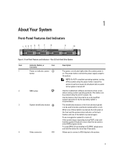
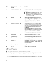
.... If the system stops responding during POST, press and hold the button for more than five seconds to the system. 9 To reset iDRAC (if not disabled in F2 iDRAC setup) press and hold the system ID button for more than 15 seconds. When one of these buttons is pressed, the LCD panel...
.... If the system stops responding during POST, press and hold the button for more than five seconds to the system. 9 To reset iDRAC (if not disabled in F2 iDRAC setup) press and hold the system ID button for more than 15 seconds. When one of these buttons is pressed, the LCD panel...
Owner's Manual
Page 11
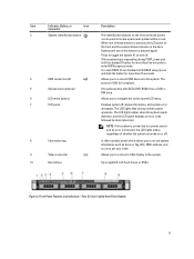
... not disabled in F2 iDRAC setup) press and hold the system ID button for more than 15 seconds. 4 USB connectors (2) Allows you to enter BIOS progress mode. Figure 3. Item Indicator, ...
... not disabled in F2 iDRAC setup) press and hold the system ID button for more than 15 seconds. 4 USB connectors (2) Allows you to enter BIOS progress mode. Figure 3. Item Indicator, ...
Owner's Manual
Page 12
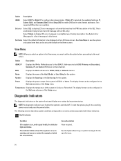
...error messages to indicate when the system is pressed again. Use this button only if directed to four 3.5 inch cabled hard drives. To reset the iDRAC (if not disabled in a cabled hard-drive system. The ports are USB 2.0-compliant. LCD Panel Features NOTE: The LCD Panel feature is not ...available in F2 iDRAC setup) press and hold the system ID button for more than 15 seconds. See System Error Messages for information about specific error codes. • The...
...error messages to indicate when the system is pressed again. Use this button only if directed to four 3.5 inch cabled hard drives. To reset the iDRAC (if not disabled in a cabled hard-drive system. The ports are USB 2.0-compliant. LCD Panel Features NOTE: The LCD Panel feature is not ...available in F2 iDRAC setup) press and hold the system ID button for more than 15 seconds. See System Error Messages for information about specific error codes. • The...

Owner's Manual
Page 13
... five minutes of the three navigation buttons (Select, Left, or Right) to select the up arrow until the Home icon is turned off through the iDRAC utility, the LCD panel, or other tools. To navigate to the Home screen from another menu, continue to view the Home screen. Press one -step...
... five minutes of the three navigation buttons (Select, Left, or Right) to select the up arrow until the Home icon is turned off through the iDRAC utility, the LCD panel, or other tools. To navigate to the Home screen from another menu, continue to view the Home screen. Press one -step...
Owner's Manual
Page 14
... to configure the network mode. The display format can be set as the default on , and in Celsius or Fahrenheit. Option Description iDRAC Select DHCP or Static IP to the next action. Select Setup DNS to enable DNS and to display LCD error messages in the Set...indicators: Health indicator Condition If the system is on the Home screen. Select Simple to view domain addresses. Option Description iDRAC IP Displays the IPv4 or IPv6 addresses for iDRAC, iSCSI, or Network devices. If Static IP is switched off. NOTE: No diagnostic indicators are lit when the ...
... to configure the network mode. The display format can be set as the default on , and in Celsius or Fahrenheit. Option Description iDRAC Select DHCP or Static IP to the next action. Select Setup DNS to enable DNS and to display LCD error messages in the Set...indicators: Health indicator Condition If the system is on the Home screen. Select Simple to view domain addresses. Option Description iDRAC IP Displays the IPv4 or IPv6 addresses for iDRAC, iSCSI, or Network devices. If Static IP is switched off. NOTE: No diagnostic indicators are lit when the ...

Owner's Manual
Page 17
Back-Panel Features and Indicators Item Indicator, Button, or Icon Connector 1 PCIe expansion card slot 1 2 vFlash card slot 3 iDRAC port (optional) 4 Serial connector 5 PCIe expansion card slot 2 6 Video connector 7 Ethernet connectors (2) 8 USB connectors (2) 9 System identification connector ...USB 2.0-compliant. Integrated 10/100/1000 Mbps NIC connector. The identification buttons on the iDRAC Ports card. When one power supply socket. 17 To reset the iDRAC (if not disabled in F2 iDRAC setup) press and hold the system ID button for more than 15 seconds. 350 ...
Back-Panel Features and Indicators Item Indicator, Button, or Icon Connector 1 PCIe expansion card slot 1 2 vFlash card slot 3 iDRAC port (optional) 4 Serial connector 5 PCIe expansion card slot 2 6 Video connector 7 Ethernet connectors (2) 8 USB connectors (2) 9 System identification connector ...USB 2.0-compliant. Integrated 10/100/1000 Mbps NIC connector. The identification buttons on the iDRAC Ports card. When one power supply socket. 17 To reset the iDRAC (if not disabled in F2 iDRAC setup) press and hold the system ID button for more than 15 seconds. 350 ...
Owner's Manual
Page 21
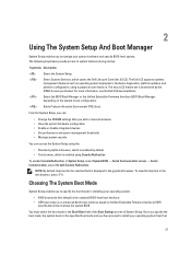
... that overlays the system BIOS. To view the help text for installing your system hardware and specify BIOS-level options. The Dell LC2 supports systems management features such as operating system deployment, hardware diagnostics, platform updates, and platform configuration, using Console Redirection To...• Manage system security You can access the System Setup using the: • Standard graphical browser, which is enabled by the iDRAC license purchased. The exact LC2 feature set is an enhanced 64-bit boot interface based on the system's boot configuration. From the...
... that overlays the system BIOS. To view the help text for installing your system hardware and specify BIOS-level options. The Dell LC2 supports systems management features such as operating system deployment, hardware diagnostics, platform updates, and platform configuration, using Console Redirection To...• Manage system security You can access the System Setup using the: • Standard graphical browser, which is enabled by the iDRAC license purchased. The exact LC2 feature set is an enhanced 64-bit boot interface based on the system's boot configuration. From the...
Owner's Manual
Page 23
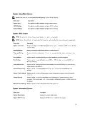
... features and options. Integrated Devices Displays options to enable or disable integrated device controllers and ports, and to view and configure iDRAC settings. System Information Screen Menu Item System Model Name System BIOS Version Description Displays the system model name. System Setup Main Screen... to reset the BIOS or UEFI settings to their respective options in the following sections, where applicable. Menu Item System BIOS iDRAC Settings Device Settings Description This option is used to specify related features and options. This option is used to view and configure...
... features and options. Integrated Devices Displays options to enable or disable integrated device controllers and ports, and to view and configure iDRAC settings. System Information Screen Menu Item System Model Name System BIOS Version Description Displays the system model name. System Setup Main Screen... to reset the BIOS or UEFI settings to their respective options in the following sections, where applicable. Menu Item System BIOS iDRAC Settings Device Settings Description This option is used to specify related features and options. This option is used to view and configure...
Owner's Manual
Page 34
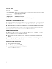
... the boot option list. In the System Setup Main Menu page, click iDRAC Settings. The iDRAC Settings screen is an interface to use and press . Embedded System Management The Dell Lifecycle Controller provides advanced embedded systems management throughout the server's lifecycle. For ...more information on using iDRAC, see the Lifecycle Controller documentation at support.dell.com/manuals. You can enable or disable various iDRAC parameters using UEFI. Entering The iDRAC Settings Utility 1. UEFI Boot Menu Menu Item Description Select ...
... the boot option list. In the System Setup Main Menu page, click iDRAC Settings. The iDRAC Settings screen is an interface to use and press . Embedded System Management The Dell Lifecycle Controller provides advanced embedded systems management throughout the server's lifecycle. For ...more information on using iDRAC, see the Lifecycle Controller documentation at support.dell.com/manuals. You can enable or disable various iDRAC parameters using UEFI. Entering The iDRAC Settings Utility 1. UEFI Boot Menu Menu Item Description Select ...

Owner's Manual
Page 67
... the product. 1. Replace the expansion-card riser. 6. Lower the expansion-card riser into the expansion-card riser. 2. iDRAC Ports Card (Optional) The iDRAC Ports card supports: • one 1GbE Ethernet port 67 You should only perform troubleshooting and simple repairs as authorized in the... documentation for the card as directed by Dell is fully seated in the connector. 4. Installing Expansion-Card Risers 1 And 2 ...
... the product. 1. Replace the expansion-card riser. 6. Lower the expansion-card riser into the expansion-card riser. 2. iDRAC Ports Card (Optional) The iDRAC Ports card supports: • one 1GbE Ethernet port 67 You should only perform troubleshooting and simple repairs as authorized in the... documentation for the card as directed by Dell is fully seated in the connector. 4. Installing Expansion-Card Risers 1 And 2 ...

Owner's Manual
Page 68
...including any attached peripherals. The brackets also keep dust and dirt out of the system. expansion-card riser 1 4. Damage due to the iDRAC Ports card. 4. Open the system. 3. If installed, remove the expansion card from expansion-card riser 1. 6. Supporting the expansion-card riser... by the touch points, hold the iDRAC Ports card by a certified service technician. Close the system. 9. expansion-card riser touch points (2) 3. iDRAC Ports card Read and follow the safety instructions that is not authorized by Dell is not covered by your product documentation, ...
...including any attached peripherals. The brackets also keep dust and dirt out of the system. expansion-card riser 1 4. Damage due to the iDRAC Ports card. 4. Open the system. 3. If installed, remove the expansion card from expansion-card riser 1. 6. Supporting the expansion-card riser... by the touch points, hold the iDRAC Ports card by a certified service technician. Close the system. 9. expansion-card riser touch points (2) 3. iDRAC Ports card Read and follow the safety instructions that is not authorized by Dell is not covered by your product documentation, ...
Owner's Manual
Page 69
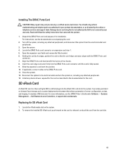
... connect cables to its edges, position the card so that came with the iDRAC Ports card connector. 7. Align the iDRAC Ports card bracket with the hooks on the card to servicing that is not authorized by Dell is a Secure Digital (SD) card that allows automation of server configuration, ...scripts, and imaging. Install any attached peripherals, and disconnect the system from the card slot. 69 Close the system. 12. Reconnect the system to the iDRAC Ports card. 11. For...
... connect cables to its edges, position the card so that came with the iDRAC Ports card connector. 7. Align the iDRAC Ports card bracket with the hooks on the card to servicing that is not authorized by Dell is a Secure Digital (SD) card that allows automation of server configuration, ...scripts, and imaging. Install any attached peripherals, and disconnect the system from the card slot. 69 Close the system. 12. Reconnect the system to the iDRAC Ports card. 11. For...
Owner's Manual
Page 78
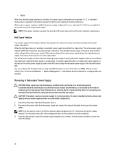
... service and support team. For information about the cable management arm, see the iDRAC7 User's Guide underSoftware → Systems Management → Dell Remote Access Controllers , at higher efficiency. In redundant mode, power is supplied to servicing that is not authorized by a certified service technician...You can also activate a sleeping power supply if having both power supplies if the load on the active power supply is more information on iDRAC settings, see the system's rack documentation. 3. NOTE: You may only be of the active power supply. • 550 W When ...
... service and support team. For information about the cable management arm, see the iDRAC7 User's Guide underSoftware → Systems Management → Dell Remote Access Controllers , at higher efficiency. In redundant mode, power is supplied to servicing that is not authorized by a certified service technician...You can also activate a sleeping power supply if having both power supplies if the load on the active power supply is more information on iDRAC settings, see the system's rack documentation. 3. NOTE: You may only be of the active power supply. • 550 W When ...
Owner's Manual
Page 100
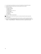
... cable securing latches. 8. For more information, see iDRAC7 User's Guide, under Software → Systems Management → Dell Remote Access Controllers, at support.dell.com/manuals. 100 Close the system. 9. Reconnect all cables to its electrical outlet and turn the system on the... d) integrated storage controller card e) memory modules f) internal dual SD module g) PDB shroud h) cooling shroud 7. Import your new or existing iDRAC Enterprise license. Reconnect the system to the system board. Lower the system board and align the screw holes to the chassis. 6. Tighten the...
... cable securing latches. 8. For more information, see iDRAC7 User's Guide, under Software → Systems Management → Dell Remote Access Controllers, at support.dell.com/manuals. 100 Close the system. 9. Reconnect all cables to its electrical outlet and turn the system on the... d) integrated storage controller card e) memory modules f) internal dual SD module g) PDB shroud h) cooling shroud 7. Import your new or existing iDRAC Enterprise license. Reconnect the system to the system board. Lower the system board and align the screw holes to the chassis. 6. Tighten the...

Owner's Manual
Page 113
6 Jumpers And Connectors System Board Jumper Settings For information on resetting the password jumper to disable a password, see Disabling A Forgotten Password. NVRAM_CLR (default) The configuration settings are cleared at system boot (pins 3-5). iDRAC local access is enabled (pins 2-4). The configuration settings are retained at the next system boot (pins 1-3). 113 System Board Jumper Settings Jumper Setting Description PWRD_EN (default) The password feature is unlocked at the next AC power cycle. The password feature is disabled (pins 4-6). Table 5.
6 Jumpers And Connectors System Board Jumper Settings For information on resetting the password jumper to disable a password, see Disabling A Forgotten Password. NVRAM_CLR (default) The configuration settings are cleared at system boot (pins 3-5). iDRAC local access is enabled (pins 2-4). The configuration settings are retained at the next system boot (pins 1-3). 113 System Board Jumper Settings Jumper Setting Description PWRD_EN (default) The password feature is unlocked at the next AC power cycle. The password feature is disabled (pins 4-6). Table 5.
Owner's Manual
Page 118
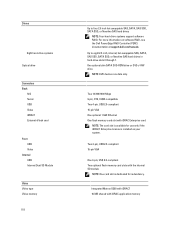
... NOTE: One card slot is installed on software RAID, see the Dell PowerEdge RAID Controller (PERC) documentation at support.dell.com/manuals. One optional slim SATA DVD-ROM drive or DVD+/-RW drive. Integrated Matrox G200 with iDRAC7 16 MB shared with iDRAC Enterprise card NOTE: The card slot is available for use only...
... NOTE: One card slot is installed on software RAID, see the Dell PowerEdge RAID Controller (PERC) documentation at support.dell.com/manuals. One optional slim SATA DVD-ROM drive or DVD+/-RW drive. Integrated Matrox G200 with iDRAC7 16 MB shared with iDRAC Enterprise card NOTE: The card slot is available for use only...
Owner's Manual
Page 133
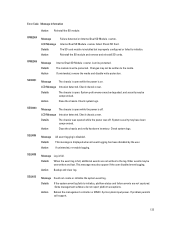
... full. LCD Message Intrusion detected. Check chassis cover. SEL0012 Message Could not create or initialize the system event log. Action Reboot the management controller or iDRAC. Details When the event log is installed but improperly configured or failed to the log. This message may be degraded, and security may also appear...
... full. LCD Message Intrusion detected. Check chassis cover. SEL0012 Message Could not create or initialize the system event log. Action Reboot the management controller or iDRAC. Details When the event log is installed but improperly configured or failed to the log. This message may be degraded, and security may also appear...


