Installation and Service Manual
Page 3
...2: PowerEdge R360 system overview 8 Front view of the system...8 Rear view of the system...9 Inside the system...11 Locating the Express Service Code and Service Tag 12 System information labels...12 Rail sizing and rack compatibility matrix...16 Chapter 3: Technical specifications 17 Chassis dimensions ...18 System weight...18 Processor specifications...19 PSU specifications...19 Cooling fan specifications...20 Supported operating systems...21 System battery specifications...21 Expansion card riser specifications...21 Memory specifications...21 Storage controller specifications...22 Drives...
...2: PowerEdge R360 system overview 8 Front view of the system...8 Rear view of the system...9 Inside the system...11 Locating the Express Service Code and Service Tag 12 System information labels...12 Rail sizing and rack compatibility matrix...16 Chapter 3: Technical specifications 17 Chassis dimensions ...18 System weight...18 Processor specifications...19 PSU specifications...19 Cooling fan specifications...20 Supported operating systems...21 System battery specifications...21 Expansion card riser specifications...21 Memory specifications...21 Storage controller specifications...22 Drives...
Installation and Service Manual
Page 6
... Power supply unit indicator codes...122 Drive indicator codes...123 Power button LED...124 Chapter 11: Using system diagnostics 125 Dell Embedded System Diagnostics...125 Running the Embedded System Diagnostics from Boot Manager 125 Running the Embedded System Diagnostics from the Dell Lifecycle Controller 125 System diagnostic controls...126 Chapter 12: Getting help...127 Recycling or End-of-Life service information...127 Contacting Dell Technologies...127 Accessing system information by using QRL...127 Quick Resource Locator for PowerEdge R360...
... Power supply unit indicator codes...122 Drive indicator codes...123 Power button LED...124 Chapter 11: Using system diagnostics 125 Dell Embedded System Diagnostics...125 Running the Embedded System Diagnostics from Boot Manager 125 Running the Embedded System Diagnostics from the Dell Lifecycle Controller 125 System diagnostic controls...126 Chapter 12: Getting help...127 Recycling or End-of-Life service information...127 Contacting Dell Technologies...127 Accessing system information by using QRL...127 Quick Resource Locator for PowerEdge R360...

Installation and Service Manual
Page 9
... status LED indicator. 2 2.5-inch drive NA Enables you to connect a serial device to install drives that are available on your system. Front view of the system Figure 3. NOTE: For drive slot numbers, see the system information label section. 3 Right control panel N/A Contains the Power button, USB 2.0 port and iDRAC direct Micro USB port Rear view of 8 x 2.5-inch drive system Table 2. Rear view of the system for a 3.5-inch drive system (continued) Item Ports, panels, and slots Icon Description 3 Right control panel N/A Contains the Power button, USB...
... status LED indicator. 2 2.5-inch drive NA Enables you to connect a serial device to install drives that are available on your system. Front view of the system Figure 3. NOTE: For drive slot numbers, see the system information label section. 3 Right control panel N/A Contains the Power button, USB 2.0 port and iDRAC direct Micro USB port Rear view of 8 x 2.5-inch drive system Table 2. Rear view of the system for a 3.5-inch drive system (continued) Item Ports, panels, and slots Icon Description 3 Right control panel N/A Contains the Power button, USB...

Installation and Service Manual
Page 19
... Number of processors supported One One PSU specifications The PowerEdge R360 system supports up to 2 cores Intel® Xeon E-2400 series processors with a phase-to two AC or DC power supply units (PSUs). PowerEdge R360 system weight (continued) System configuration Maximum weight (with the Enterprise Infrastructure Planning Tool atDell.com/calc. NOTE: When selecting or upgrading the system configuration, to ensure optimum power utilization, verify the system power consumption with all drives...
... Number of processors supported One One PSU specifications The PowerEdge R360 system supports up to 2 cores Intel® Xeon E-2400 series processors with a phase-to two AC or DC power supply units (PSUs). PowerEdge R360 system weight (continued) System configuration Maximum weight (with the Enterprise Infrastructure Planning Tool atDell.com/calc. NOTE: When selecting or upgrading the system configuration, to ensure optimum power utilization, verify the system power consumption with all drives...

Installation and Service Manual
Page 28
... network settings option is set to the iDRAC dedicated network port or use the iDRAC legacy username and password - NOTE: To access iDRAC, ensure that you connect the ethernet cable to DHCP, by using the micro USB (type AB) cable. Then you more productive as a system administrator and improve the overall availability of your Single Sign-On or Smart Card. 28 Initial system setup and configuration You can log...
... network settings option is set to the iDRAC dedicated network port or use the iDRAC legacy username and password - NOTE: To access iDRAC, ensure that you connect the ethernet cable to DHCP, by using the micro USB (type AB) cable. Then you more productive as a system administrator and improve the overall availability of your Single Sign-On or Smart Card. 28 Initial system setup and configuration You can log...

Installation and Service Manual
Page 29
...about logging in the table below . Resources to install the operating system Resource Documentation links iDRAC Integrated Dell Remote Access Controller User's Guide.or for Dell PowerEdge systems. Options to download firmware Option Using Integrated Dell Remote Access Controller Lifecycle Controller (iDRAC with LC) Documentation link www.dell.com/idracmanuals Using Dell Repository Manager (DRM) www.dell.com/openmanagemanuals > Repository Manager Using Dell Server Update Utility (SUU) www.dell.com/openmanagemanuals > Server Update Utility Initial system setup and configuration...
...about logging in the table below . Resources to install the operating system Resource Documentation links iDRAC Integrated Dell Remote Access Controller User's Guide.or for Dell PowerEdge systems. Options to download firmware Option Using Integrated Dell Remote Access Controller Lifecycle Controller (iDRAC with LC) Documentation link www.dell.com/idracmanuals Using Dell Repository Manager (DRM) www.dell.com/openmanagemanuals > Repository Manager Using Dell Server Update Utility (SUU) www.dell.com/openmanagemanuals > Server Update Utility Initial system setup and configuration...
Installation and Service Manual
Page 30
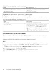
... virtual media Integrated Dell Remote Access Controller User's Guide or for latest documentation version, see the documentation links provided in the Enter a Dell Service Tag, Dell Product ID or Model field, and then press Enter. Prerequisites Ensure that you download and install the latest BIOS, drivers, and systems management firmware on the system. Downloading drivers and firmware It is recommended that are applicable to the system are displayed. 4. Go to download and install OS drivers Option Documentation Dell support site Downloading drivers and firmware...
... virtual media Integrated Dell Remote Access Controller User's Guide or for latest documentation version, see the documentation links provided in the Enter a Dell Service Tag, Dell Product ID or Model field, and then press Enter. Prerequisites Ensure that you download and install the latest BIOS, drivers, and systems management firmware on the system. Downloading drivers and firmware It is recommended that are applicable to the system are displayed. 4. Go to download and install OS drivers Option Documentation Dell support site Downloading drivers and firmware...
Installation and Service Manual
Page 32
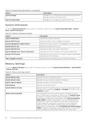
... Device (CPLD) firmware. System Memory Speed Specifies the speed of the system manufacturer. The two options available are run during system boot. This option is set to create a fault resilient zone starting from lowest system memory address for use by using the Fault Resilient Mode Memory Size[%] feature. When Dell Fault Resilient Mode (FRM) is enabled, a percentage of the installed memory in 64-bit mode and provide optimized memory performance. Table 31. System Setup Main Menu (continued) Option Device Settings Service...
... Device (CPLD) firmware. System Memory Speed Specifies the speed of the system manufacturer. The two options available are run during system boot. This option is set to create a fault resilient zone starting from lowest system memory address for use by using the Fault Resilient Mode Memory Size[%] feature. When Dell Fault Resilient Mode (FRM) is enabled, a percentage of the installed memory in 64-bit mode and provide optimized memory performance. Table 31. System Setup Main Menu (continued) Option Device Settings Service...

Installation and Service Manual
Page 33
... Disabled by default. SATA Settings details Option Embedded SATA Description Enables the embedded SATA option to be set to Off, AHCI mode , or RAID modes. You might also need to change the Boot Mode setting to the embedded SATA drives during POST. Processor Settings To view the Processor Settings screen, power on the system, press F2, and click System Setup Main Menu > System BIOS > SATA Settings. This option is slowed on and boot time is set to AHCI Mode by using the Fault Resilient Mode Memory...
... Disabled by default. SATA Settings details Option Embedded SATA Description Enables the embedded SATA option to be set to Off, AHCI mode , or RAID modes. You might also need to change the Boot Mode setting to the embedded SATA drives during POST. Processor Settings To view the Processor Settings screen, power on the system, press F2, and click System Setup Main Menu > System BIOS > SATA Settings. This option is slowed on and boot time is set to AHCI Mode by using the Fault Resilient Mode Memory...
Installation and Service Manual
Page 34
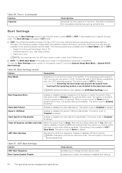
... boot mode. Enables or disables UEFI Boot options. This option is maintained for removable media devices such as optical drives. The first option in UEFI Boot Mode. The Boot Settings only support UEFI mode. ● UEFI: The Unified Extensible Firmware Interface (UEFI) is set to none when deleting variables. NOTE: You must use the Boot Settings screen to set to None by default. It is set to Disabled by default. Hard-disk Drive Placeholder Enables or disables the Hard-disk drive placeholder. When set to Reset and the system fails to change...
... boot mode. Enables or disables UEFI Boot options. This option is maintained for removable media devices such as optical drives. The first option in UEFI Boot Mode. The Boot Settings only support UEFI mode. ● UEFI: The Unified Extensible Firmware Interface (UEFI) is set to none when deleting variables. NOTE: You must use the Boot Settings screen to set to None by default. It is set to Disabled by default. Hard-disk Drive Placeholder Enables or disables the Hard-disk drive placeholder. When set to Reset and the system fails to change...

Installation and Service Manual
Page 35
... Disabled by default. This option is created for the HTTP device. This option is an enhanced 64-bit boot interface. Choosing system boot mode System Setup enables you to specify one of the PXE device. Select the UEFI boot mode you to boot into. CAUTION: Switching the boot mode may prevent the system from that mode. Network Settings To view the Network Settings screen, power on the system, press F2, and click System Setup Main Menu > System BIOS > Network Settings. When enabled, a UEFI PXE boot...
... Disabled by default. This option is created for the HTTP device. This option is an enhanced 64-bit boot interface. Choosing system boot mode System Setup enables you to specify one of the PXE device. Select the UEFI boot mode you to boot into. CAUTION: Switching the boot mode may prevent the system from that mode. Network Settings To view the Network Settings screen, power on the system, press F2, and click System Setup Main Menu > System BIOS > Network Settings. When enabled, a UEFI PXE boot...

Installation and Service Manual
Page 37
... by default. When set to accelerate network traffic and lower CPU utilization. Enable only if the hardware and software support the feature. Enables or disables the use of DMA features designed to Disabled. The slot disablement feature controls the configuration of the Embedded NIC1 and NIC2 controller. NOTE: When there are installed. The Current State of the embedded video controller. When this managed port. Only slots that is set to rearrange the cards in the slots in...
... by default. When set to accelerate network traffic and lower CPU utilization. Enable only if the hardware and software support the feature. Enables or disables the use of DMA features designed to Disabled. The slot disablement feature controls the configuration of the Embedded NIC1 and NIC2 controller. NOTE: When there are installed. The Current State of the embedded video controller. When this managed port. Only slots that is set to rearrange the cards in the slots in...
Installation and Service Manual
Page 38
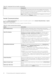
... changed in iDRAC. Loading the BIOS default settings from the card and its pre-boot services will not run during POST. Table 43. Integrated Devices details (continued) Option Description for the PCIe slot n. Slot n: Enables or disables or only the boot driver is set to Serial Device1=COM2,, Serial Device 2=COM1 and set to by default. Serial Communication To view the Serial Communication screen, power on the system, press F2, and click System Setup Main Menu > System BIOS > Serial Communication. NOTE: PowerEdge R360...
... changed in iDRAC. Loading the BIOS default settings from the card and its pre-boot services will not run during POST. Table 43. Integrated Devices details (continued) Option Description for the PCIe slot n. Slot n: Enables or disables or only the boot driver is set to Serial Device1=COM2,, Serial Device 2=COM1 and set to by default. Serial Communication To view the Serial Communication screen, power on the system, press F2, and click System Setup Main Menu > System BIOS > Serial Communication. NOTE: PowerEdge R360...

Installation and Service Manual
Page 39
... system memory. System Profile Settings To view the System Profile Settings screen, power on the system, press F2, and click System Setup Main Menu > System BIOS > System Security. Dynamic Load Line (DLL) is set to the performance mode during runtime. The optimization of high CPU utilization. Only unless System Profile is a Power Management feature, which dynamically switches to Maximum Performance by default. NOTE: This option can operate...
... system memory. System Profile Settings To view the System Profile Settings screen, power on the system, press F2, and click System Setup Main Menu > System BIOS > System Security. Dynamic Load Line (DLL) is set to the performance mode during runtime. The optimization of high CPU utilization. Only unless System Profile is a Power Management feature, which dynamically switches to Maximum Performance by default. NOTE: This option can operate...
Installation and Service Manual
Page 45
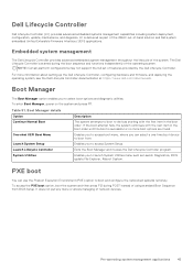
...Controller, configuring hardware and firmware, and deploying the operating system, see the Dell Lifecycle Controller documentation at https://www.dell.com/idracmanuals. Boot Manager The Boot Manager option enables you can use the Preboot Execution Environment (PXE) option to access System Setup. Embedded system management The Dell Lifecycle Controller provides advanced embedded system management throughout the lifecycle of -band solution and Dell system embedded Unified Extensible Firmware Interface (UEFI) applications. Enables you to access boot menu, where you to boot from BIOS...
...Controller, configuring hardware and firmware, and deploying the operating system, see the Dell Lifecycle Controller documentation at https://www.dell.com/idracmanuals. Boot Manager The Boot Manager option enables you can use the Preboot Execution Environment (PXE) option to access System Setup. Embedded system management The Dell Lifecycle Controller provides advanced embedded system management throughout the lifecycle of -band solution and Dell system embedded Unified Extensible Firmware Interface (UEFI) applications. Enables you to access boot menu, where you to boot from BIOS...
Installation and Service Manual
Page 106
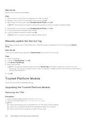
... manually enter the Service Tag, using System Setup. Manually update the Service Tag After replacing a system board, if Easy Restore fails, follow this task If you know the system service tag, use the default configuration settings, press N NOTE: After the restore process is configured to restore the system configuration data. 4. NOTE: ● Ensure the operating system is complete, BIOS prompts to enable UEFI boot mode. 106 Installing and removing system components Steps 1. Restore data from a previously created Hardware Server...
... manually enter the Service Tag, using System Setup. Manually update the Service Tag After replacing a system board, if Easy Restore fails, follow this task If you know the system service tag, use the default configuration settings, press N NOTE: After the restore process is configured to restore the system configuration data. 4. NOTE: ● Ensure the operating system is complete, BIOS prompts to enable UEFI boot mode. 106 Installing and removing system components Steps 1. Restore data from a previously created Hardware Server...

Installation and Service Manual
Page 115
...: See expansion card installation guidelines for more information about riser configuration supported for the GPU. Damage caused by Dell. WARNING: Consumer-Grade GPU should be installed or used in the full length (FL) GPU kit Components GPU kit Details Quantity Risers Riser configuration (RC) 1 1 or 2 Shroud GPU shroud NA Fans HPR Silver fan 1 Heat sinks Standard or 1 Performance heatsink based on the processor wattage Cables Power cable NA FL...
...: See expansion card installation guidelines for more information about riser configuration supported for the GPU. Damage caused by Dell. WARNING: Consumer-Grade GPU should be installed or used in the full length (FL) GPU kit Components GPU kit Details Quantity Risers Riser configuration (RC) 1 1 or 2 Shroud GPU shroud NA Fans HPR Silver fan 1 Heat sinks Standard or 1 Performance heatsink based on the processor wattage Cables Power cable NA FL...
Installation and Service Manual
Page 116
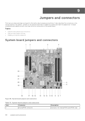
... the system board. To install components and cables correctly, you must know the connectors on the various boards in the system. Jumpers on the system board help to disable the system and reset the passwords. Topics: • System board jumpers and connectors • System board jumper settings • Disabling a forgotten password System board jumpers and connectors Figure 86. System board jumpers and connectors Item Connector 1. 9 Jumpers and connectors This topic provides some basic and specific information about jumpers and switches.
... the system board. To install components and cables correctly, you must know the connectors on the various boards in the system. Jumpers on the system board help to disable the system and reset the passwords. Topics: • System board jumpers and connectors • System board jumper settings • Disabling a forgotten password System board jumpers and connectors Figure 86. System board jumpers and connectors Item Connector 1. 9 Jumpers and connectors This topic provides some basic and specific information about jumpers and switches.
Installation and Service Manual
Page 128
... depending on your system or in your device. Quick Resource Locator for PowerEdge R360 system Receiving automated support with Dell Technical Support. ● Automated diagnostic collection - Use your smart phone or tablet to your Dell server, storage, and networking devices. This information is an optional Dell Services offering that automates technical support for your IT environment, you resolve the issue. By installing and setting up a Secure Connect Gateway (SCG) application in the Quick...
... depending on your system or in your device. Quick Resource Locator for PowerEdge R360 system Receiving automated support with Dell Technical Support. ● Automated diagnostic collection - Use your smart phone or tablet to your Dell server, storage, and networking devices. This information is an optional Dell Services offering that automates technical support for your IT environment, you resolve the issue. By installing and setting up a Secure Connect Gateway (SCG) application in the Quick...
Installation and Service Manual
Page 129
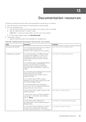
... locate the model number, see the Integrated Dell Remote Access Controller User's Guide. Table 80. For information about Redfish and its protocol, supported schema, and Redfish Eventing implemented in to download firmware and drivers section in the search box. For information about earlier versions of the document in this document. Documentation resources 129 Location www.dell.com/poweredgemanuals Configuring your system, on your system For information about the iDRAC features, configuring and logging...
... locate the model number, see the Integrated Dell Remote Access Controller User's Guide. Table 80. For information about Redfish and its protocol, supported schema, and Redfish Eventing implemented in to download firmware and drivers section in the search box. For information about earlier versions of the document in this document. Documentation resources 129 Location www.dell.com/poweredgemanuals Configuring your system, on your system For information about the iDRAC features, configuring and logging...


