
Glossary
Page 1
...CD, diskette, or USB memory key that contains a processor, memory, and a hard drive. Your system contains an expansion bus that allows the processor to communicate with MIB data from the hard drive. cache - cm - Centimeter(s). 1 Alternating current. Advanced Configuration and Power Interface. The ... Common Information Model describes the management information utilized by an administrator, for enabling the operating system to the system. Dell™ Glossary NOTE: For additional information on storage terminology, visit the Storage Networking Industry Association's website at www....
...CD, diskette, or USB memory key that contains a processor, memory, and a hard drive. Your system contains an expansion bus that allows the processor to communicate with MIB data from the hard drive. cache - cm - Centimeter(s). 1 Alternating current. Advanced Configuration and Power Interface. The ... Common Information Model describes the management information utilized by an administrator, for enabling the operating system to the system. Dell™ Glossary NOTE: For additional information on storage terminology, visit the Storage Networking Industry Association's website at www....

Glossary
Page 2
... driver. Error checking and correction. Embedded remote access. ESM - controller - DNS - ECC - Embedded server management. An add-in -line memory module. A chip that controls the transfer of specific processing tasks. DVD - EMI - expansion card - An expansion card adds some other program.... ERA allows you to the system by transferring data on the system board. Electrostatic discharge. DHCP - Dynamic Host Configuration Protocol. COMn - The device names for example, handles numeric processing. Your system contains an expansion bus that plugs ...
... driver. Error checking and correction. Embedded remote access. ESM - controller - DNS - ECC - Embedded server management. An add-in -line memory module. A chip that controls the transfer of specific processing tasks. DVD - EMI - expansion card - An expansion card adds some other program.... ERA allows you to the system by transferring data on the system board. Electrostatic discharge. DHCP - Dynamic Host Configuration Protocol. COMn - The device names for example, handles numeric processing. Your system contains an expansion bus that plugs ...

Glossary
Page 6
...RAID arrays, a striped hard drive containing parity data. PowerEdge RAID controller. Power-on a video display. A provider...A single point on self-test. Pixels are arranged in a rack. A way of sources. Nanosecond(s). Memory that communicates with a block of a CIM schema that does not lose its contents when you turn off ... an implementation-specific integer or pointer that is a synonym for maintaining the date, time, and system configuration information. pixel - processor - Software written for local-bus implementation. PXE - Preboot eXecution Environment. parity...
...RAID arrays, a striped hard drive containing parity data. PowerEdge RAID controller. Power-on a video display. A provider...A single point on self-test. Pixels are arranged in a rack. A way of sources. Nanosecond(s). Memory that communicates with a block of a CIM schema that does not lose its contents when you turn off ... an implementation-specific integer or pointer that is a synonym for maintaining the date, time, and system configuration information. pixel - processor - Software written for local-bus implementation. PXE - Preboot eXecution Environment. parity...

Glossary
Page 8
... and how the system should be connected and disconnected while the system is running. system memory - TOE - UPS - Universal Serial Bus. USB devices can be configured for operation. SNMP - A virtual disk may need to enable or disable the termination ... I/O devices. system board - See RAM. USB - system configuration information - See memory key. 8 Uninterruptible power supply. TCP/IP offload engine. SMP - USB memory key - striping - A port on each processor has equal access to configure your system in an array, but only uses a portion of...
... and how the system should be connected and disconnected while the system is running. system memory - TOE - UPS - Universal Serial Bus. USB devices can be configured for operation. SNMP - A virtual disk may need to enable or disable the termination ... I/O devices. system board - See RAM. USB - system configuration information - See memory key. 8 Uninterruptible power supply. TCP/IP offload engine. SMP - USB memory key - striping - A port on each processor has equal access to configure your system in an array, but only uses a portion of...
Glossary
Page 53
Dell Storage Networking Industry Association www.snia.org A Ampere AC Alternating Current ACPI Advanced Configuration and Power Interface ANSI American National Standards Institute BMC Baseboard Management Controller BTU British Thermal Unit C - 섭씨 (... CIM SNMP MIB cm Centimeter COMn CPU Central Processing Unit DC Direct Current DDR Double-Data Rate DHCP Dynamic Host Configuration Protocol IP DIMM Dual In-line Memory Module DNS Domain Name System www.example.com 208.77.188.166 과 같은 IP DRAM Dynamic Random...
Dell Storage Networking Industry Association www.snia.org A Ampere AC Alternating Current ACPI Advanced Configuration and Power Interface ANSI American National Standards Institute BMC Baseboard Management Controller BTU British Thermal Unit C - 섭씨 (... CIM SNMP MIB cm Centimeter COMn CPU Central Processing Unit DC Direct Current DDR Double-Data Rate DHCP Dynamic Host Configuration Protocol IP DIMM Dual In-line Memory Module DNS Domain Name System www.example.com 208.77.188.166 과 같은 IP DRAM Dynamic Random...

Owner's Manual
Page 4
... The System...37 Cooling Shroud...39 Removing The Cooling Shroud...39 Installing The Cooling Shroud...40 System Memory...41 General Memory Module Installation Guidelines 43 Mode-Specific Guidelines...43 Sample Memory Configurations...44 Removing Memory Modules...45 Installing Memory Modules...46 Hard Drives...47 Removing A 2.5 Inch Hard-Drive Blank...48 Installing A 2.5 Inch Hard-Drive Blank...48...
... The System...37 Cooling Shroud...39 Removing The Cooling Shroud...39 Installing The Cooling Shroud...40 System Memory...41 General Memory Module Installation Guidelines 43 Mode-Specific Guidelines...43 Sample Memory Configurations...44 Removing Memory Modules...45 Installing Memory Modules...46 Hard Drives...47 Removing A 2.5 Inch Hard-Drive Blank...48 Installing A 2.5 Inch Hard-Drive Blank...48...
Owner's Manual
Page 15
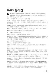
Health indicator Condition Corrective Action Invalid memory configurations can cause the system to indicate hard-drive activity.. If the problem persists, see Getting Help. 15 Reinstall the memory device. Corrective Action None required. Re-seat the power supply by removing and reinstalling it is...conditions exist: • A cooling fan is removed or has failed. • System cover, cooling shroud, EMI filler panel, memory- Temperature indicator Condition The indicator blinks amber if the system experiences a thermal error (for the location of range or fan failure). ...
Health indicator Condition Corrective Action Invalid memory configurations can cause the system to indicate hard-drive activity.. If the problem persists, see Getting Help. 15 Reinstall the memory device. Corrective Action None required. Re-seat the power supply by removing and reinstalling it is...conditions exist: • A cooling fan is removed or has failed. • System cover, cooling shroud, EMI filler panel, memory- Temperature indicator Condition The indicator blinks amber if the system experiences a thermal error (for the location of range or fan failure). ...
Owner's Manual
Page 23
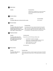
... their respective options in the following sections, where applicable. Menu Item System BIOS iDRAC Settings Device Settings Description This option is used to view and configure device settings. Memory Settings Displays information and options related to specify the boot mode (BIOS or UEFI). Boot Settings Displays options to installed...
... their respective options in the following sections, where applicable. Menu Item System BIOS iDRAC Settings Device Settings Description This option is used to view and configure device settings. Memory Settings Displays information and options related to specify the boot mode (BIOS or UEFI). Boot Settings Displays options to installed...

Owner's Manual
Page 24
... Technology option is set to Disabled, the BIOS only displays one logical processor per core. If this field is Enabled, memory interleaving is supported if a symmetric memory configuration is set to Enabled. Video Memory Displays the amount of system manufacturer. Options are run during system boot. By default, the Adjacent Cache Line Prefetch option...
... Technology option is set to Disabled, the BIOS only displays one logical processor per core. If this field is Enabled, memory interleaving is supported if a symmetric memory configuration is set to Enabled. Video Memory Displays the amount of system manufacturer. Options are run during system boot. By default, the Adjacent Cache Line Prefetch option...

Owner's Manual
Page 41
Reconnect the system to its electrical outlet and turn the system on : • DIMM type (UDIMM or RDIMM) • DIMM configuration (number of ranks) • maximum frequency of the DIMMs • number of DIMMs populated per second. 4. It supports DDR3 and ... voltage • system profile selected (for example, Performance Optimized, Custom, or Dense Configuration Optimized) • maximum supported DIMM frequency of the first socket are marked white and the second socket black. 41 System Memory Your system supports DDR3 unbuffered ECC DIMMs (ECC UDIMMs) and registered DIMMs (RDIMMs)....
Reconnect the system to its electrical outlet and turn the system on : • DIMM type (UDIMM or RDIMM) • DIMM configuration (number of ranks) • maximum frequency of the DIMMs • number of DIMMs populated per second. 4. It supports DDR3 and ... voltage • system profile selected (for example, Performance Optimized, Custom, or Dense Configuration Optimized) • maximum supported DIMM frequency of the first socket are marked white and the second socket black. 41 System Memory Your system supports DDR3 unbuffered ECC DIMMs (ECC UDIMMs) and registered DIMMs (RDIMMs)....

Owner's Manual
Page 42
... and 800 1333, 1066, and 800 1066 and 800 Dual rank Quad rank 42 Figure 15. Memory Socket Locations Memory channels are organized as follows: channel 0: memory sockets A1 and A4 channel 1: memory sockets A2 and A5 channel 2: memory sockets A3 and A6 The following table shows the memory populations and operating frequencies for the supported configurations.
... and 800 1333, 1066, and 800 1066 and 800 Dual rank Quad rank 42 Figure 15. Memory Socket Locations Memory channels are organized as follows: channel 0: memory sockets A1 and A4 channel 1: memory sockets A2 and A5 channel 2: memory sockets A3 and A6 The following table shows the memory populations and operating frequencies for the supported configurations.

Owner's Manual
Page 43
... can prevent your system from x4 DRAM based DIMMs to both x4 and x8 DRAMs. This protects against single DRAM chip failures during memory configuration, or operating with white release tabs first, and then black. • Populate the sockets by highest rank count in the following ... and 800 1333, 1066, and 800 1066 and 800 1066 and 800 Maximum DIMM Rank/ Channel Dual rank Quad rank General Memory Module Installation Guidelines NOTE: Memory configurations that fail to observe these guidelines can be populated in a channel. • Populate all guidelines for specific RAS features must ...
... can prevent your system from x4 DRAM based DIMMs to both x4 and x8 DRAMs. This protects against single DRAM chip failures during memory configuration, or operating with white release tabs first, and then black. • Populate the sockets by highest rank count in the following ... and 800 1333, 1066, and 800 1066 and 800 1066 and 800 Maximum DIMM Rank/ Channel Dual rank Quad rank General Memory Module Installation Guidelines NOTE: Memory configurations that fail to observe these guidelines can be populated in a channel. • Populate all guidelines for specific RAS features must ...

Owner's Manual
Page 44
... channel is disabled. NOTE: 1R and 2R in this section. With memory sparing enabled, the system memory available to the spare rank and the failed rank is reserved as a spare. Sample Memory Configurations The following table shows sample memory configurations that follow the appropriate memory guidelines stated in the following table indicates single- Half of the installed...
... channel is disabled. NOTE: 1R and 2R in this section. With memory sparing enabled, the system memory available to the spare rank and the failed rank is reserved as a spare. Sample Memory Configurations The following table shows sample memory configurations that follow the appropriate memory guidelines stated in the following table indicates single- Half of the installed...

Owner's Manual
Page 47
... ensure that the host adapter is configured correctly to its electrical outlet and turn off or reboot your system while the hard drive is running, see Using System Diagnostics. Hot-swappable hard drives are firmly seated in only one of hours to reflect the newly installed memory. 13. Hard Drives Depending on...
... ensure that the host adapter is configured correctly to its electrical outlet and turn off or reboot your system while the hard drive is running, see Using System Diagnostics. Hot-swappable hard drives are firmly seated in only one of hours to reflect the newly installed memory. 13. Hard Drives Depending on...

Owner's Manual
Page 126
... device may be seated correctly, misconfigured, or has failed. MEM0001 Message Multi-bit memory errors detected on a memory device at location . If the issue persists, see Getting Help . LCD Message Unsupported memory configuration. Action Re-seat the memory modules. MEM0007 Message Unsupported memory configuration; System functionality may fail as a result. Check hardware. Check connection. HWC1001 Message The...
... device may be seated correctly, misconfigured, or has failed. MEM0001 Message Multi-bit memory errors detected on a memory device at location . If the issue persists, see Getting Help . LCD Message Unsupported memory configuration. Action Re-seat the memory modules. MEM0007 Message Unsupported memory configuration; System functionality may fail as a result. Check hardware. Check connection. HWC1001 Message The...

Owner's Manual
Page 127
... Action Check the memory configuration. This an early indicator of a possible future uncorrectable error. Action Re-seat the memory modules. Re-seat memory. If the issue persists, see Getting Help. If the issue persists, see Getting Help. Check memory device at location . Action Check the memory configuration. Re-seat the memory modules. LCD Message Correctable memory error rate exceeded...
... Action Check the memory configuration. This an early indicator of a possible future uncorrectable error. Action Re-seat the memory modules. Re-seat memory. If the issue persists, see Getting Help. If the issue persists, see Getting Help. Check memory device at location . Action Check the memory configuration. Re-seat the memory modules. LCD Message Correctable memory error rate exceeded...

Owner's Manual
Page 129
...or lost . PDR1016 Message Drive is detected. Details The controller detected that the drive was unable to configure the memory for power supply is lost. PST0129 Message Memory is detected, but was unable to detect memory in the system. Action Remove and reinstall the power supply at the next service window. Check PSU ... LCD Message Action Power supply failed. Re-seat the failed drive. Details The power supply is installed correctly but is attached to supported system memory configurations. LCD Message Power input for the power supply.
...or lost . PDR1016 Message Drive is detected. Details The controller detected that the drive was unable to configure the memory for power supply is lost. PST0129 Message Memory is detected, but was unable to detect memory in the system. Action Remove and reinstall the power supply at the next service window. Check PSU ... LCD Message Action Power supply failed. Re-seat the failed drive. Details The power supply is installed correctly but is attached to supported system memory configurations. LCD Message Power input for the power supply.
Technical Guide
Page 3
... ...6 2 System features ...7 Comparison of PowerEdge systems ...7 Specifications ...8 3 Chassis views and features ...11 Chassis views ...11 Chassis features ...12 4 Processor ...15 Processor features...15 Supported processors...15 Chipset ...16 5 Memory ...17 Supported memory ...17 Memory configurations ...18 Memory speed ...19 Memory RAS features...20 6 Storage ...21 Internal...systems and virtualization ...34 Supported operating systems...34 Supported virtualization ...35 11 Dell OpenManage systems management...36 Systems management solutions ...36 OpenManage systems management ...37...
... ...6 2 System features ...7 Comparison of PowerEdge systems ...7 Specifications ...8 3 Chassis views and features ...11 Chassis views ...11 Chassis features ...12 4 Processor ...15 Processor features...15 Supported processors...15 Chipset ...16 5 Memory ...17 Supported memory ...17 Memory configurations ...18 Memory speed ...19 Memory RAS features...20 6 Storage ...21 Internal...systems and virtualization ...34 Supported operating systems...34 Supported virtualization ...35 11 Dell OpenManage systems management...36 Systems management solutions ...36 OpenManage systems management ...37...

Technical Guide
Page 18
... the lowest DIMM slots, followed by the SR DIMMs. For more information on memory configuration, see the Dell PowerEdge R320 Systems Owner's Manual on supported memory, visit Dell.com. rank (QR), dual- DIMMs supported Capacity Speed (GB) (MT/s) Type Ranks per processor. Table 8. The R320 has 3 memory channels per channel. • DIMMs must be installed in each channel supporting...
... the lowest DIMM slots, followed by the SR DIMMs. For more information on memory configuration, see the Dell PowerEdge R320 Systems Owner's Manual on supported memory, visit Dell.com. rank (QR), dual- DIMMs supported Capacity Speed (GB) (MT/s) Type Ranks per processor. Table 8. The R320 has 3 memory channels per channel. • DIMMs must be installed in each channel supporting...

Technical Guide
Page 19
...speed supported by the processor, the speed settings in the BIOS, and the operating voltage of the system. Table 9 lists memory configuration and performance details for the channel with DIMM speeds of 1333MT/s and 1600MT/s on all processors and channels run at the ...at the highest speed for the R320 based on the DIMM types installed and the configuration. Memory speed The R320 supports memory speeds of 1600MT/s, 1333MT/s, 1066MT/s, and 800MT/s depending on the population of the number and type of DIMMs per memory channel. All memory on Dell.com. 19 PowerEdge R320 Technical Guide
...speed supported by the processor, the speed settings in the BIOS, and the operating voltage of the system. Table 9 lists memory configuration and performance details for the channel with DIMM speeds of 1333MT/s and 1600MT/s on all processors and channels run at the ...at the highest speed for the R320 based on the DIMM types installed and the configuration. Memory speed The R320 supports memory speeds of 1600MT/s, 1333MT/s, 1066MT/s, and 800MT/s depending on the population of the number and type of DIMMs per memory channel. All memory on Dell.com. 19 PowerEdge R320 Technical Guide


