
Glossary
Page 1
Dell™ Glossary NOTE: For additional information on storage terminology, ...unit. Your system contains an expansion bus that allows the processor to communicate with MIB data from the hard drive. A fast storage area that is located. It provides mapping techniques for quick data retrieval. The temperature...system also contains an address bus and a data bus for the peripheral devices connected to start your system's hard drive(s) on the dictionary. Common Information Model describes the management information utilized by an administrator, for developing technology standards...
Dell™ Glossary NOTE: For additional information on storage terminology, ...unit. Your system contains an expansion bus that allows the processor to communicate with MIB data from the hard drive. A fast storage area that is located. It provides mapping techniques for quick data retrieval. The temperature...system also contains an address bus and a data bus for the peripheral devices connected to start your system's hard drive(s) on the dictionary. Common Information Model describes the management information utilized by an administrator, for developing technology standards...

Glossary
Page 3
...of electronic chip that can be differentiated from computational activity. A controller that uses the Internet SCSI protocol. Hertz. Integrated Dell Remote Access Controller. IP - Fahrenheit. The file system structure used primarily with high-speed peripherals. The Microsoft® Windows...Gigabyte(s); 1024 megabytes or 1,073,741,824 bytes. host adapter - A keyboard is an input device, and a monitor is usually rounded to hard-drive capacity, the term is an output device. A standard interface between the processor and the main memory (RAM). iDRAC - flash memory - ...
...of electronic chip that can be differentiated from computational activity. A controller that uses the Internet SCSI protocol. Hertz. Integrated Dell Remote Access Controller. IP - Fahrenheit. The file system structure used primarily with high-speed peripherals. The Microsoft® Windows...Gigabyte(s); 1024 megabytes or 1,073,741,824 bytes. host adapter - A keyboard is an input device, and a monitor is usually rounded to hard-drive capacity, the term is an output device. A standard interface between the processor and the main memory (RAM). iDRAC - flash memory - ...

Glossary
Page 5
...to serve specific storage needs. NAS systems have their own operating systems, integrated hardware, and software that is monitored and managed using Dell OpenManage™ Server Administrator. A device that are optimized to a network. 5 A system used for implementing shared storage on ...(s). NAS is any system that contains the CIM schema definition. management station - Megabyte(s); 1,048,576 bytes. However, when referring to hard-drive capacity, the term is provided by software. Mbps - A portable flash memory storage device integrated with a USB connector. A type of...
...to serve specific storage needs. NAS systems have their own operating systems, integrated hardware, and software that is monitored and managed using Dell OpenManage™ Server Administrator. A device that are optimized to a network. 5 A system used for implementing shared storage on ...(s). NAS is any system that contains the CIM schema definition. management station - Megabyte(s); 1,048,576 bytes. However, when referring to hard-drive capacity, the term is provided by software. Mbps - A portable flash memory storage device integrated with a USB connector. A type of...

Glossary
Page 6
...Object identifier is a synonym for one processor must format each logical drive with the fdisk command. In RAID arrays, a striped hard drive containing parity data. You can contain multiple logical drives. Peripheral Component Interconnect. PDU - Power-on another processor. RAC ... a CIM schema that is expressed as RAM and hard drives. Preboot eXecution Environment. NVRAM is an extension of sources. Redundant information that communicates with a block of arithmetic and logic functions. PowerEdge RAID controller. Nonvolatile random-access memory. parity stripe ...
...Object identifier is a synonym for one processor must format each logical drive with the fdisk command. In RAID arrays, a striped hard drive containing parity data. You can contain multiple logical drives. Peripheral Component Interconnect. PDU - Power-on another processor. RAC ... a CIM schema that is expressed as RAM and hard drives. Preboot eXecution Environment. NVRAM is an extension of sources. Redundant information that communicates with a block of arithmetic and logic functions. PowerEdge RAID controller. Nonvolatile random-access memory. parity stripe ...

Glossary
Page 7
...-access memory. System event log. A legacy I /O bus interface with faster data transmission rates than standard ports. service tag - SMART - Allows hard drives to report errors and failures to the system BIOS and then display an error message on the system used to connect a modem to its contents... on the screen. 7 RAID - Random-access memory. read -only file is one bit at a time and is lost when you call Dell for program instructions and data. Read-only memory. RAID on motherboard. Serial-attached SCSI. sec - See also mirroring and striping. Redundant array of...
...-access memory. System event log. A legacy I /O bus interface with faster data transmission rates than standard ports. service tag - SMART - Allows hard drives to report errors and failures to the system BIOS and then display an error message on the system used to connect a modem to its contents... on the screen. 7 RAID - Random-access memory. read -only file is one bit at a time and is lost when you call Dell for program instructions and data. Read-only memory. RAID on motherboard. Serial-attached SCSI. sec - See also mirroring and striping. Redundant array of...

User Manual
Page 6
... installing hardware or software not purchased with the operating system. For customers outside the United States, visit support.dell.com and select your system's hard drive. Installing the Optional Bezel Install the bezel (optional). Complete The Operating System Setup If you do not accept...Bezel Figure 6. If you purchased a preinstalled operating system, see the installation and configuration documentation for your operating system. NOTE: See dell.com/ossupport for the first time, see the documentation associated with the system. For customers in the United States, call the customer...
... installing hardware or software not purchased with the operating system. For customers outside the United States, visit support.dell.com and select your system's hard drive. Installing the Optional Bezel Install the bezel (optional). Complete The Operating System Setup If you do not accept...Bezel Figure 6. If you purchased a preinstalled operating system, see the installation and configuration documentation for your operating system. NOTE: See dell.com/ossupport for the first time, see the documentation associated with the system. For customers in the United States, call the customer...

Owner's Manual
Page 3
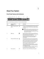
... Warnings 2 1 About Your System...9 Front-Panel Features And Indicators...9 LCD Panel Features...12 Home Screen...13 Setup Menu...13 View Menu...14 Diagnostic Indicators...14 Hard-Drive Indicator Patterns...16 Back-Panel Features And Indicators...17 NIC Indicator Codes...18 Power Indicator Codes...18 Other Information You May Need...19 2 Using The...
... Warnings 2 1 About Your System...9 Front-Panel Features And Indicators...9 LCD Panel Features...12 Home Screen...13 Setup Menu...13 View Menu...14 Diagnostic Indicators...14 Hard-Drive Indicator Patterns...16 Back-Panel Features And Indicators...17 NIC Indicator Codes...18 Power Indicator Codes...18 Other Information You May Need...19 2 Using The...

Owner's Manual
Page 4
... Hard-Drive Blank...48 Installing A 2.5 Inch Hard-Drive Blank...48 Removing A 3.5 Inch Hard-Drive Blank...48 Installing A 3.5 Inch Hard-Drive Blank...49 Removing A Hot-Swap Hard Drive...49 Installing A Hot-Swap Hard Drive...50 Removing A Cabled Hard Drive...51 Installing A Cabled Hard Drive...51 Removing A 2.5 Inch Hard Drive From A 3.5 Inch Hard-Drive Adapter 52 Installing A 2.5 Inch Hard Drive Into A 3.5 Inch Hard-Drive Adapter 53 Removing A Hard Drive Or A Hard-Drive Adapter From A Hard-Drive Carrier 53 Installing A Hard Drive Or A Hard-Drive Adapter Into A Hard-Drive...
... Hard-Drive Blank...48 Installing A 2.5 Inch Hard-Drive Blank...48 Removing A 3.5 Inch Hard-Drive Blank...48 Installing A 3.5 Inch Hard-Drive Blank...49 Removing A Hot-Swap Hard Drive...49 Installing A Hot-Swap Hard Drive...50 Removing A Cabled Hard Drive...51 Installing A Cabled Hard Drive...51 Removing A 2.5 Inch Hard Drive From A 3.5 Inch Hard-Drive Adapter 52 Installing A 2.5 Inch Hard Drive Into A 3.5 Inch Hard-Drive Adapter 53 Removing A Hard Drive Or A Hard-Drive Adapter From A Hard-Drive Carrier 53 Installing A Hard Drive Or A Hard-Drive Adapter Into A Hard-Drive...
Owner's Manual
Page 5
Installing The Optical Drive In Hot-Swappable Hard-Drive Systems 56 Removing The Optical Drive In Cabled Hard-Drive Systems 57 Installing The Optical Drive In Cabled Hard-Drive Systems 58 Cooling Fans...59 Removing A Cooling Fan...59 Installing A Cooling Fan...60 Internal USB Memory Key (Optional)...61 Replacing The Internal USB Key...61 ... A Non-Redundant Power Supply...79 Removing The Power Supply Blank...79 Installing The Power Supply Blank...80 System Battery...80 Replacing The System Battery...80 Hard-Drive Backplane...81
Installing The Optical Drive In Hot-Swappable Hard-Drive Systems 56 Removing The Optical Drive In Cabled Hard-Drive Systems 57 Installing The Optical Drive In Cabled Hard-Drive Systems 58 Cooling Fans...59 Removing A Cooling Fan...59 Installing A Cooling Fan...60 Internal USB Memory Key (Optional)...61 Replacing The Internal USB Key...61 ... A Non-Redundant Power Supply...79 Removing The Power Supply Blank...79 Installing The Power Supply Blank...80 System Battery...80 Replacing The System Battery...80 Hard-Drive Backplane...81
Owner's Manual
Page 6
Removing The Hard-Drive Backplane...81 Installing The Hard-Drive Backplane...86 Control Panel Assembly...87 Removing The Control Panel...87 Installing The Control Panel...88 Removing The Control-Panel Module...89 Installing The Control... Cooling Problems...104 Troubleshooting Cooling Fans...105 Troubleshooting System Memory...105 Troubleshooting An Internal USB Key...106 Troubleshooting An SD Card...106 Troubleshooting An Optical Drive...107 Troubleshooting A Tape Backup Unit...107 Troubleshooting A Hard Drive...108 Troubleshooting A Storage Controller...108 Troubleshooting Expansion Cards...109
Removing The Hard-Drive Backplane...81 Installing The Hard-Drive Backplane...86 Control Panel Assembly...87 Removing The Control Panel...87 Installing The Control Panel...88 Removing The Control-Panel Module...89 Installing The Control... Cooling Problems...104 Troubleshooting Cooling Fans...105 Troubleshooting System Memory...105 Troubleshooting An Internal USB Key...106 Troubleshooting An SD Card...106 Troubleshooting An Optical Drive...107 Troubleshooting A Tape Backup Unit...107 Troubleshooting A Hard Drive...108 Troubleshooting A Storage Controller...108 Troubleshooting Expansion Cards...109
Owner's Manual
Page 9
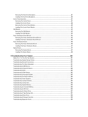
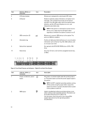
... the power button causes the system to perform a graceful shutdown before power to locate a particular system within a rack. Front-Panel Features and Indicators-Four 3.5 Inch Hard-Drive System Item Indicator, Button, or Icon Description Connector 1 Power-on indicator, power button The power-on . NOTE: On ACPI-compliant operating systems, turning off the...
... the power button causes the system to perform a graceful shutdown before power to locate a particular system within a rack. Front-Panel Features and Indicators-Four 3.5 Inch Hard-Drive System Item Indicator, Button, or Icon Description Connector 1 Power-on indicator, power button The power-on . NOTE: On ACPI-compliant operating systems, turning off the...
Owner's Manual
Page 10
... support personnel or by descriptive text. Figure 2. The power button controls the power supply output to four 3.5 inch or 2.5 inch hot-swappable hard drives, or SSDs. NOTE: If the system is connected to a power source and an error is detected, the LCD lights amber regardless of whether...turned on or off the system using the end of a paper clip. Up to the system. Front-Panel Features and Indicators-Eight 2.5 Inch Hard-Drive System Item Indicator, Button, or Icon Description Connector 1 Power-on indicator, power button The power-on indicator lights when the system power is ...
... support personnel or by descriptive text. Figure 2. The power button controls the power supply output to four 3.5 inch or 2.5 inch hot-swappable hard drives, or SSDs. NOTE: If the system is connected to a power source and an error is detected, the LCD lights amber regardless of whether...turned on or off the system using the end of a paper clip. Up to the system. Front-Panel Features and Indicators-Eight 2.5 Inch Hard-Drive System Item Indicator, Button, or Icon Description Connector 1 Power-on indicator, power button The power-on indicator lights when the system power is ...

Owner's Manual
Page 11
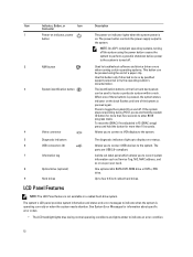
...hold the button for more than five seconds to the system. Figure 3. Front-Panel Features and Indicators-Four 3.5 Inch Cabled Hard-Drive System 11 Item Indicator, Button, or Icon Description Connector 3 System identification button The identification buttons on the front and back...are USB 2.0-compliant. 5 Optical drive (optional) One optional ultra slim SATA DVD-ROM drive or DVD+/RW drive. 6 LCD menu buttons Allows you to eight 2.5 inch hard drives, or SSDs. Allows you to connect a VGA display to the system. 10 Hard drives Up to record system information ...
...hold the button for more than five seconds to the system. Figure 3. Front-Panel Features and Indicators-Four 3.5 Inch Cabled Hard-Drive System 11 Item Indicator, Button, or Icon Description Connector 3 System identification button The identification buttons on the front and back...are USB 2.0-compliant. 5 Optical drive (optional) One optional ultra slim SATA DVD-ROM drive or DVD+/RW drive. 6 LCD menu buttons Allows you to eight 2.5 inch hard drives, or SSDs. Allows you to connect a VGA display to the system. 10 Hard drives Up to record system information ...
Owner's Manual
Page 12
... perform a graceful shutdown before power to the system is turned off . Use this button only if directed to four 3.5 inch cabled hard drives. The ports are USB 2.0-compliant. Allows you to connect USB devices to indicate when the system is pressed again. The system's LCD...panel which allows you to connect a VGA display to the system. 5 Diagnostic indicators 6 USB connectors (2) 7 Information tag 8 Optical drive (optional) 9 Hard drives The diagnostic indicators light up to the system. When one of these buttons is not available in F2 iDRAC setup) press and hold ...
... perform a graceful shutdown before power to the system is turned off . Use this button only if directed to four 3.5 inch cabled hard drives. The ports are USB 2.0-compliant. Allows you to connect USB devices to indicate when the system is pressed again. The system's LCD...panel which allows you to connect a VGA display to the system. 5 Diagnostic indicators 6 USB connectors (2) 7 Information tag 8 Optical drive (optional) 9 Hard drives The diagnostic indicators light up to the system. When one of these buttons is not available in F2 iDRAC setup) press and hold ...
Owner's Manual
Page 14
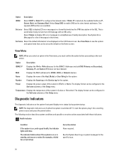
... the network mode. Power Displays the power output of the Setup menu. See the System Event Log or system messages for example, a failed fan or hard drive) Corrective Action None required. The following section describes system conditions and possible corrective actions associated with an SEL entry. Select Simple to the next action...
... the network mode. Power Displays the power output of the Setup menu. See the System Event Log or system messages for example, a failed fan or hard drive) Corrective Action None required. The following section describes system conditions and possible corrective actions associated with an SEL entry. Select Simple to the next action...
Owner's Manual
Page 15
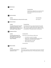
... blinks amber if the system experiences a thermal error (for the specific issue. Reinstall the memory device. See Getting Help. Hard-drive indicator Condition The indicator lights green to halt at startup without any video output. Corrective Action None required. If the problem..., voltage out of the failed memory. Health indicator Condition Corrective Action Invalid memory configurations can cause the system to indicate hard-drive activity.. If it . Electrical indicator Condition The indicator blinks amber if the system experiences an electrical error (for the location...
... blinks amber if the system experiences a thermal error (for the specific issue. Reinstall the memory device. See Getting Help. Hard-drive indicator Condition The indicator lights green to halt at startup without any video output. Corrective Action None required. If the problem..., voltage out of the failed memory. Health indicator Condition Corrective Action Invalid memory configurations can cause the system to indicate hard-drive activity.. If it . Electrical indicator Condition The indicator blinks amber if the system experiences an electrical error (for the location...

Owner's Manual
Page 16
...Hard-Drive Indicator Patterns Figure 5. Hard-Drive Indicators 1. hard-drive status indicator (green and amber) NOTE: If the hard drive is turned on the right side) does not function and remains off. Blinks green, amber, and off Blinks amber four times per second Off Condition Identifying drive or preparing for removal Drive...mode, the status indicator (on . Re-install the card. hard-drive activity indicator (green) 2. PCIe indicator Condition The indicator blinks amber if a PCIe card experiences an error. Drive-Status Indicator Pattern (RAID Only) Blinks green two times per ...
...Hard-Drive Indicator Patterns Figure 5. Hard-Drive Indicators 1. hard-drive status indicator (green and amber) NOTE: If the hard drive is turned on the right side) does not function and remains off. Blinks green, amber, and off Blinks amber four times per second Off Condition Identifying drive or preparing for removal Drive...mode, the status indicator (on . Re-install the card. hard-drive activity indicator (green) 2. PCIe indicator Condition The indicator blinks amber if a PCIe card experiences an error. Drive-Status Indicator Pattern (RAID Only) Blinks green two times per ...
Owner's Manual
Page 17
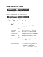
... 7. The identification buttons on 17 The ports are USB 2.0-compliant. Connects the optional system status indicator assembly through the optional cable management arm. Hot-swappable hard-drive systems When one low-profile PCI Express expansion card. 2 vFlash media card slot (optional) Allows you to insert an optional vFlash media card. 3 iDRAC port...
... 7. The identification buttons on 17 The ports are USB 2.0-compliant. Connects the optional system status indicator assembly through the optional cable management arm. Hot-swappable hard-drive systems When one low-profile PCI Express expansion card. 2 vFlash media card slot (optional) Allows you to insert an optional vFlash media card. 3 iDRAC port...
Owner's Manual
Page 38
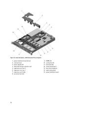
Figure 12. expansion-card holder 8. power distribution board 38 power supplies (2) 4. expansion-card riser 2 6. cable routing latch 15. power distribution board shroud 2. integrated storage controller card 5. Inside the System-With Redundant Power Supplies 1. expansion-card riser 1 7. cooling shroud 3. hard-drive backplane 14. DIMMs (6) 10. hard drives (8) 12. processor heat sink 9. control-panel board 13. cooling fans (5) 11.
Figure 12. expansion-card holder 8. power distribution board 38 power supplies (2) 4. expansion-card riser 2 6. cable routing latch 15. power distribution board shroud 2. integrated storage controller card 5. Inside the System-With Redundant Power Supplies 1. expansion-card riser 1 7. cooling shroud 3. hard-drive backplane 14. DIMMs (6) 10. hard drives (8) 12. processor heat sink 9. control-panel board 13. cooling fans (5) 11.
Owner's Manual
Page 39
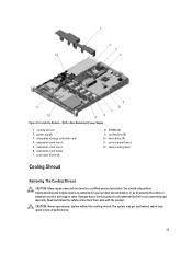
... repairs as directed by the online or telephone service and support team. power supply 3. Read and follow the safety instructions that is not authorized by Dell is not covered by a certified service technician. cooling shroud 2. expansion-card riser 1 6. processor heat sink 8. control panel board 12. CAUTION: Never operate your product documentation... servicing that came with the product. The system may get overheated, which may only be done by your warranty. expansion-card holder 7. DIMMs (6) 9. Figure 13. hard drives (4) 11.
... repairs as directed by the online or telephone service and support team. power supply 3. Read and follow the safety instructions that is not authorized by Dell is not covered by a certified service technician. cooling shroud 2. expansion-card riser 1 6. processor heat sink 8. control panel board 12. CAUTION: Never operate your product documentation... servicing that came with the product. The system may get overheated, which may only be done by your warranty. expansion-card holder 7. DIMMs (6) 9. Figure 13. hard drives (4) 11.


