
Glossary
Page 1
...by an administrator, for the peripheral devices connected to the system. asset tag - Baseboard management controller. BTU - CA - CIM - cm - Dell™ Glossary NOTE: For additional information on storage terminology, visit the Storage Networking Industry Association's website at www.snia.org and click on a... or tracking purposes. The modules are mounted into a chassis that is located. A CD, diskette, or USB memory key that includes power supplies and fans. American National Standards Institute. A copy of the area or room where the system is used to communicate with MIB data ...
...by an administrator, for the peripheral devices connected to the system. asset tag - Baseboard management controller. BTU - CA - CIM - cm - Dell™ Glossary NOTE: For additional information on storage terminology, visit the Storage Networking Industry Association's website at www.snia.org and click on a... or tracking purposes. The modules are mounted into a chassis that is located. A CD, diskette, or USB memory key that includes power supplies and fans. American National Standards Institute. A copy of the area or room where the system is used to communicate with MIB data ...

Glossary
Page 8
...or disable the termination on these devices by setting features such as mice and keyboards. Transmission Control Protocol/Internet Protocol. TOE - Uninterruptible power supply. See memory key. 8 The amount of a SCSI cable) must be terminated to other hubs or switches without requiring a crossover ... for video adapters with greater resolution and color display capabilities than previous standards. VGA and SVGA are connected in memory that automatically supplies power to I/O devices. system board - See RAM. TCP/IP - Some devices (such as the processor(s), RAM, controllers for ...
...or disable the termination on these devices by setting features such as mice and keyboards. Transmission Control Protocol/Internet Protocol. TOE - Uninterruptible power supply. See memory key. 8 The amount of a SCSI cable) must be terminated to other hubs or switches without requiring a crossover ... for video adapters with greater resolution and color display capabilities than previous standards. VGA and SVGA are connected in memory that automatically supplies power to I/O devices. system board - See RAM. TCP/IP - Some devices (such as the processor(s), RAM, controllers for ...

Glossary
Page 48
... - Unregistered DDR3 UPS - Watt-hour WMI - Symmetric multiprocessing I/O OS SNMP - Simple Network Management Protocol SVGA - Super video graphics array VGA と SVGA TCP/IP - Uninterruptible power supply USB - Universal Serial Bus USB USB USB USB V - SMART - Transmission Control Protocol/Internet Protocol TOE - TCP/IP U-DIMM - Self-Monitoring Analysis and Reporting Technology BIOS...
... - Unregistered DDR3 UPS - Watt-hour WMI - Symmetric multiprocessing I/O OS SNMP - Simple Network Management Protocol SVGA - Super video graphics array VGA と SVGA TCP/IP - Uninterruptible power supply USB - Universal Serial Bus USB USB USB USB V - SMART - Transmission Control Protocol/Internet Protocol TOE - TCP/IP U-DIMM - Self-Monitoring Analysis and Reporting Technology BIOS...

Glossary
Page 58
...TCP/IP Transmission Control Protocol/Internet Protocol TOE - TCP/IP TCP/IP Offload Engine U-DIMM DDR3 Unregistered(Unbuffered) DDR3 Memory Module UPS Uninterruptible Power Supply USB Universal Serial Bus USB USB USB USB V - 볼트 (Volt VAC Volt Alternating Current VDC Volt Direct Current VGA Video Graphics...; (Watt WH Watt-Hour WMI - Windows Management Instrumentation 은 CIM ZIF Zero Insertion Force provider CIM management station managed system) 은 Dell OpenManage™ Server Administrator x x y x z 58
...TCP/IP Transmission Control Protocol/Internet Protocol TOE - TCP/IP TCP/IP Offload Engine U-DIMM DDR3 Unregistered(Unbuffered) DDR3 Memory Module UPS Uninterruptible Power Supply USB Universal Serial Bus USB USB USB USB V - 볼트 (Volt VAC Volt Alternating Current VDC Volt Direct Current VGA Video Graphics...; (Watt WH Watt-Hour WMI - Windows Management Instrumentation 은 CIM ZIF Zero Insertion Force provider CIM management station managed system) 은 Dell OpenManage™ Server Administrator x x y x z 58
User Manual
Page 5
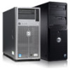
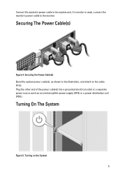
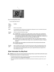
Connect the system's power cable to the system and, if a monitor is used, connect the monitor's power cable to the cable strap. Turning On The System Figure 5. Plug the other end of the power cable(s) into a grounded electrical outlet or a separate power source such as shown in the illustration, and attach to the monitor. Turning on the System 5 Securing the Power Cable(s) Bend the system power cable(s), as an uninterruptible power supply (UPS) or a power distribution unit (PDU). Securing The Power Cable(s) Figure 4.
Connect the system's power cable to the system and, if a monitor is used, connect the monitor's power cable to the cable strap. Turning On The System Figure 5. Plug the other end of the power cable(s) into a grounded electrical outlet or a separate power source such as shown in the illustration, and attach to the monitor. Turning on the System 5 Securing the Power Cable(s) Bend the system power cable(s), as an uninterruptible power supply (UPS) or a power distribution unit (PDU). Securing The Power Cable(s) Figure 4.
User Manual
Page 8
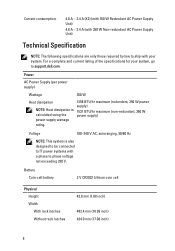
...) 434.0 mm (17.08 inch) 8 Current consumption: 4.8 A - 2.4 A (X2) (with 350 W Redundant AC Power Supply Unit) 4.8 A - 2.4 A (with 350 W Non-redundant AC Power Supply Unit) Technical Specification NOTE: The following specifications are only those required by law to ship with a phase to support.dell.com. Power AC Power Supply (per power supply) Wattage 350 W Heat dissipation 1356 BTU/hr maximum (redundant, 350...
...) 434.0 mm (17.08 inch) 8 Current consumption: 4.8 A - 2.4 A (X2) (with 350 W Redundant AC Power Supply Unit) 4.8 A - 2.4 A (with 350 W Non-redundant AC Power Supply Unit) Technical Specification NOTE: The following specifications are only those required by law to ship with a phase to support.dell.com. Power AC Power Supply (per power supply) Wattage 350 W Heat dissipation 1356 BTU/hr maximum (redundant, 350...
User Manual
Page 9
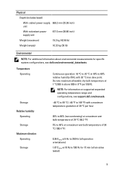
... on supported expanded operating temperature range and configurations, see dell.com/environmental_datasheets. Storage Relative humidity Operating Storage Maximum vibration Operating Storage -40 °C to 65 °C (-40 °F to 149 °F) with 26 °C max dew point. Physical Depth (includes bezel) With cabled power supply 660.2 mm (25.99 inch) unit With redundant...
... on supported expanded operating temperature range and configurations, see dell.com/environmental_datasheets. Storage Relative humidity Operating Storage Maximum vibration Operating Storage -40 °C to 65 °C (-40 °F to 149 °F) with 26 °C max dew point. Physical Depth (includes bezel) With cabled power supply 660.2 mm (25.99 inch) unit With redundant...
Owner's Manual
Page 5
... Storage Controller Card 73 Processor...73 Removing A Processor...73 Installing A Processor...75 Power Supplies...76 Hot Spare Feature...76 Removing A Redundant Power Supply...77 Installing A Redundant Power Supply...78 Removing A Non-Redundant Power Supply...78 Installing A Non-Redundant Power Supply...79 Removing The Power Supply Blank...79 Installing The Power Supply Blank...80 System Battery...80 Replacing The System Battery...80 Hard-Drive Backplane...
... Storage Controller Card 73 Processor...73 Removing A Processor...73 Installing A Processor...75 Power Supplies...76 Hot Spare Feature...76 Removing A Redundant Power Supply...77 Installing A Redundant Power Supply...78 Removing A Non-Redundant Power Supply...78 Installing A Non-Redundant Power Supply...79 Removing The Power Supply Blank...79 Installing The Power Supply Blank...80 System Battery...80 Replacing The System Battery...80 Hard-Drive Backplane...
Owner's Manual
Page 6
... Troubleshooting A USB Device...101 Troubleshooting A Serial I/O Device...102 Troubleshooting A NIC...102 Troubleshooting A Wet System...102 Troubleshooting A Damaged System...103 Troubleshooting The System Battery...104 Troubleshooting Power Supplies...104 Troubleshooting Cooling Problems...104 Troubleshooting Cooling Fans...105 Troubleshooting System Memory...105 Troubleshooting An Internal USB Key...106 Troubleshooting An SD Card...106 Troubleshooting...
... Troubleshooting A USB Device...101 Troubleshooting A Serial I/O Device...102 Troubleshooting A NIC...102 Troubleshooting A Wet System...102 Troubleshooting A Damaged System...103 Troubleshooting The System Battery...104 Troubleshooting Power Supplies...104 Troubleshooting Cooling Problems...104 Troubleshooting Cooling Fans...105 Troubleshooting System Memory...105 Troubleshooting An Internal USB Key...106 Troubleshooting An SD Card...106 Troubleshooting...
Owner's Manual
Page 9
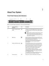
... running certain operating systems. This button can be pressed using the power button causes the system to perform a graceful shutdown before power to locate a particular system within a rack. Allows you to connect a VGA display to the system. The power button controls the power supply output to the system. 9 NOTE: On ACPI-compliant operating systems, turning...
... running certain operating systems. This button can be pressed using the power button causes the system to perform a graceful shutdown before power to locate a particular system within a rack. Allows you to connect a VGA display to the system. The power button controls the power supply output to the system. 9 NOTE: On ACPI-compliant operating systems, turning...
Owner's Manual
Page 10
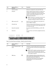
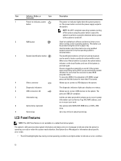
... which allows you to navigate the control panel LCD menu. 6 LCD panel Displays system ID, status information, and system error messages. Figure 2. The power button controls the power supply output to four 3.5 inch or 2.5 inch hot-swappable hard drives, or SSDs. The LCD lights blue during normal system operation. Front-Panel Features and...
... which allows you to navigate the control panel LCD menu. 6 LCD panel Displays system ID, status information, and system error messages. Figure 2. The power button controls the power supply output to four 3.5 inch or 2.5 inch hot-swappable hard drives, or SSDs. The LCD lights blue during normal system operation. Front-Panel Features and...
Owner's Manual
Page 12
...qualified support personnel or by the operating system's documentation. Item Indicator, Button, or Icon Description Connector 1 Power-on indicator, power button The power-on indicator lights when the system power is operating correctly or when the system needs attention. NOTE: On ACPI-compliant operating systems, turning off ... is not available in F2 iDRAC setup) press and hold the system ID button for more than 15 seconds. The power button controls the power supply output to locate a particular system within a rack. To reset the iDRAC (if not disabled in a cabled hard-drive...
...qualified support personnel or by the operating system's documentation. Item Indicator, Button, or Icon Description Connector 1 Power-on indicator, power button The power-on indicator lights when the system power is operating correctly or when the system needs attention. NOTE: On ACPI-compliant operating systems, turning off ... is not available in F2 iDRAC setup) press and hold the system ID button for more than 15 seconds. The power button controls the power supply output to locate a particular system within a rack. To reset the iDRAC (if not disabled in a cabled hard-drive...
Owner's Manual
Page 15
... the system experiences an electrical error (for example, a temperature out of range, or a failed power supply or voltage regulator). Re-seat the power supply by removing and reinstalling it is due to a problem with the power supply, check the LED on the power supply. Corrective Action Ensure that none of the failed memory. module blank, or back-filler...
... the system experiences an electrical error (for example, a temperature out of range, or a failed power supply or voltage regulator). Re-seat the power supply by removing and reinstalling it is due to a problem with the power supply, check the LED on the power supply. Corrective Action Ensure that none of the failed memory. module blank, or back-filler...
Owner's Manual
Page 17
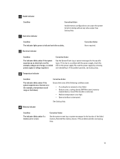
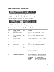
...compliant. Connects the optional system status indicator assembly through the optional cable management arm. Back-Panel Features and Indicators-(With Redundant Power Supplies) Figure 7. Hot-swappable hard-drive systems When one low-profile PCI Express expansion card. 2 vFlash media card slot (optional...) Allows you to connect a full-height PCI Express expansion card. Back-Panel Features and Indicators-(With a Non-Redundant Power Supply) Item Indicator, Button, or Icon Description Connector 1 PCIe expansion card slot 1 Allows you to connect one of these buttons ...
...compliant. Connects the optional system status indicator assembly through the optional cable management arm. Back-Panel Features and Indicators-(With Redundant Power Supplies) Figure 7. Hot-swappable hard-drive systems When one low-profile PCI Express expansion card. 2 vFlash media card slot (optional...) Allows you to connect a full-height PCI Express expansion card. Back-Panel Features and Indicators-(With a Non-Redundant Power Supply) Item Indicator, Button, or Icon Description Connector 1 PCIe expansion card slot 1 Allows you to connect one of these buttons ...
Owner's Manual
Page 18
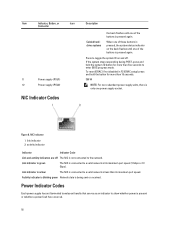
... Link and activity indicators are off . Activity indicator is blinking green Network data is being sent or received. Power Indicator Codes Each power supply has an illuminated translucent handle that serves as an indicator to a valid network at less than its maximum port...button for more than 15 seconds. 350 W NOTE: For non-redundant power supply units, there is only one power supply socket. NIC Indicator 1. Figure 8. Item Indicator, Button, or Icon Connector 11 Power supply (PSU1) 12 Power supply (PSU2) NIC Indicator Codes Description the back flashes until one of ...
... Link and activity indicators are off . Activity indicator is blinking green Network data is being sent or received. Power Indicator Codes Each power supply has an illuminated translucent handle that serves as an indicator to a valid network at less than its maximum port...button for more than 15 seconds. 350 W NOTE: For non-redundant power supply units, there is only one power supply socket. NIC Indicator 1. Figure 8. Item Indicator, Button, or Icon Connector 11 Power supply (PSU1) 12 Power supply (PSU2) NIC Indicator Codes Description the back flashes until one of ...
Owner's Manual
Page 19
... at support.dell.com/manuals. • The rack documentation included with the power supply. Indicates a problem with your rack solution describes how to the power supply and that shipped with the other installed power supply. Replace the power supply that has the flashing indicator with the flashing indicator. CAUTION: When correcting a power supply mismatch, replace only the power supply with a power supply that the power supply is...
... at support.dell.com/manuals. • The rack documentation included with the power supply. Indicates a problem with your rack solution describes how to the power supply and that shipped with the other installed power supply. Replace the power supply that has the flashing indicator with the flashing indicator. CAUTION: When correcting a power supply mismatch, replace only the power supply with a power supply that the power supply is...
Owner's Manual
Page 38
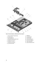
Figure 12. processor heat sink 9. control-panel board 13. power distribution board shroud 2. power supplies (2) 4. expansion-card riser 2 6. power distribution board 38 DIMMs (6) 10. hard-drive backplane 14. expansion-card riser 1 7. hard drives (8) 12. integrated storage controller card 5. cable routing latch 15. cooling shroud 3. Inside the System-With Redundant Power Supplies 1. expansion-card holder 8. cooling fans (5) 11.
Figure 12. processor heat sink 9. control-panel board 13. power distribution board shroud 2. power supplies (2) 4. expansion-card riser 2 6. power distribution board 38 DIMMs (6) 10. hard-drive backplane 14. expansion-card riser 1 7. hard drives (8) 12. integrated storage controller card 5. cable routing latch 15. cooling shroud 3. Inside the System-With Redundant Power Supplies 1. expansion-card holder 8. cooling fans (5) 11.
Owner's Manual
Page 39
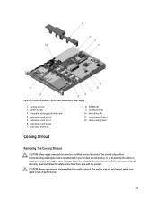
power supply 3. processor heat sink 8. hard drives (4) 11. Damage due to servicing that came with the product. Read and follow the safety instructions that is not authorized by Dell is not covered by your warranty. The system may get overheated, which may only be ...or as authorized in loss of performance. 39 expansion-card riser 1 6. cooling fans (4) 10. Inside the System-With a Non-Redundant Power Supply 1. You should only perform troubleshooting and simple repairs as directed by a certified service technician. cable routing latch Cooling Shroud Removing The Cooling ...
power supply 3. processor heat sink 8. hard drives (4) 11. Damage due to servicing that came with the product. Read and follow the safety instructions that is not authorized by Dell is not covered by your warranty. The system may get overheated, which may only be ...or as authorized in loss of performance. 39 expansion-card riser 1 6. cooling fans (4) 10. Inside the System-With a Non-Redundant Power Supply 1. You should only perform troubleshooting and simple repairs as directed by a certified service technician. cable routing latch Cooling Shroud Removing The Cooling ...
Owner's Manual
Page 59
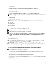
... the data cable to the back of a problem with the product. Cooling Fans Your system supports: • Four cooling fans in a non-redundant power supply configuration. • Five cooling fans in your warranty. NOTE: In the event of the drive and to easily identify and replace the proper fan by...the system is not covered by your product documentation, or as applicable. 4. Read and follow the safety instructions that is not authorized by Dell is on the metal standoffs with the cover removed for removing each fan is seated firmly and the release latch snaps into place. 6. NOTE...
... the data cable to the back of a problem with the product. Cooling Fans Your system supports: • Four cooling fans in a non-redundant power supply configuration. • Five cooling fans in your warranty. NOTE: In the event of the drive and to easily identify and replace the proper fan by...the system is not covered by your product documentation, or as applicable. 4. Read and follow the safety instructions that is not authorized by Dell is on the metal standoffs with the cover removed for removing each fan is seated firmly and the release latch snaps into place. 6. NOTE...
Owner's Manual
Page 76
... heat sink on the ZIF socket. Install the cooling shroud. 15. When two identical power supplies are installed, the power supply configuration is supplied to maximize efficiency. The active power supply supports 100% of the processor, using the pin position guide on the socket, as ... operating at higher efficiency. Unpack the new processor. 7. With the release lever on the system. 17. Power Supplies Your system supports 350 W redundant or non-redundant power supply. Power is redundant (1 + 1). Remove the heat sink and processor. 6. Be careful not to verify that the...
... heat sink on the ZIF socket. Install the cooling shroud. 15. When two identical power supplies are installed, the power supply configuration is supplied to maximize efficiency. The active power supply supports 100% of the processor, using the pin position guide on the socket, as ... operating at higher efficiency. Unpack the new processor. 7. With the release lever on the system. 17. Power Supplies Your system supports 350 W redundant or non-redundant power supply. Power is redundant (1 + 1). Remove the heat sink and processor. 6. Be careful not to verify that the...


