
iDRAC9 with Lifecycle Controller Version 3.30.30.30 RACADM CLI Guide
Page 104
... operation. It is applicable only for the PowerEdge-VRTX platform. Examples the sensor thresholds can be lesser or higher than the sensor critical threshold limit. Replace the field with -a option. serveraction Table 81. To run this operation is similar to pressing the power button on the system's front panel to turn off and...
... operation. It is applicable only for the PowerEdge-VRTX platform. Examples the sensor thresholds can be lesser or higher than the sensor critical threshold limit. Replace the field with -a option. serveraction Table 81. To run this operation is similar to pressing the power button on the system's front panel to turn off and...
iDRAC9 with Lifecycle Controller Version 3.30.30.30 RACADM CLI Guide
Page 453
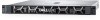
... Express or iDRAC Enterprise Dependency None BIOS.SysSecurity.SecureBoot (Read or Write) Table 1063. Details of BIOS.SysSecurity.PwrButton attribute Description Enables or disables the power button on the front panel. Legal Values • Locked • Unlocked Default Value Write Privilege Not Applicable Server Control License Required iDRAC Express or iDRAC Enterprise...
... Express or iDRAC Enterprise Dependency None BIOS.SysSecurity.SecureBoot (Read or Write) Table 1063. Details of BIOS.SysSecurity.PwrButton attribute Description Enables or disables the power button on the front panel. Legal Values • Locked • Unlocked Default Value Write Privilege Not Applicable Server Control License Required iDRAC Express or iDRAC Enterprise...
EMC PowerEdge R240 Installation and Service Manual
Page 9
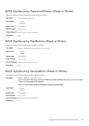
For more information on the ports, see the Technical Specifications section. System health and system ID indicator Right control panel Figure 4. iDRAC direct Micro USB port NOTE: For more information about the ports, see the Ports and connectors specifications section. Left control panel view 1. USB 2.0-compliant port 3. Dell EMC PowerEdge R240 system overview 9 Control panels Left control panel Figure 3. Power button 2. Right control panel view 1.
For more information on the ports, see the Technical Specifications section. System health and system ID indicator Right control panel Figure 4. iDRAC direct Micro USB port NOTE: For more information about the ports, see the Ports and connectors specifications section. Left control panel view 1. USB 2.0-compliant port 3. Dell EMC PowerEdge R240 system overview 9 Control panels Left control panel Figure 3. Power button 2. Right control panel view 1.
EMC PowerEdge R240 Installation and Service Manual
Page 10
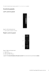
Serial port 3. Full-height PCIe expansion card slot 7. System identification button 11. NIC port (Gb 1) 4. System status indicator cable port (CMA) 12. NIC port (Gb 2) 5. USB 3.0 ports (2) 13. Half-height PCIe expansion card slot 6.... more information about the ports and connectors, see the Technical Specifications section. Rear view of the system 1. PSU Built-in Self Test (BIST) button 10. Intrusion switch 10 Dell EMC PowerEdge R240 system overview VGA port 2. Rear view of the system Figure 5. Optical drive 2. Inside the system Figure 6. Inside the system - 4 x 3.5-inch...
Serial port 3. Full-height PCIe expansion card slot 7. System identification button 11. NIC port (Gb 1) 4. System status indicator cable port (CMA) 12. NIC port (Gb 2) 5. USB 3.0 ports (2) 13. Half-height PCIe expansion card slot 6.... more information about the ports and connectors, see the Technical Specifications section. Rear view of the system 1. PSU Built-in Self Test (BIST) button 10. Intrusion switch 10 Dell EMC PowerEdge R240 system overview VGA port 2. Rear view of the system Figure 5. Optical drive 2. Inside the system Figure 6. Inside the system - 4 x 3.5-inch...
EMC PowerEdge R240 Installation and Service Manual
Page 13
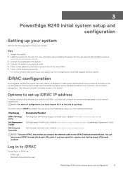
...PowerEdge R240 initial system setup and configuration 13 Log in to iDRAC You can also access iDRAC through the shared LOM mode, if you must request for it at the time of purchase. Connect the system to the system. 4. Power on your network infrastructure. iDRAC configuration The Integrated Dell.... You can set up your system: Steps 1. For more information about installing the system into the rack. Power on the system by pressing the power button or by using one of Dell systems. iDRAC alerts administrators about setting up your system, see the Rail Installation Guide at www...
...PowerEdge R240 initial system setup and configuration 13 Log in to iDRAC You can also access iDRAC through the shared LOM mode, if you must request for it at the time of purchase. Connect the system to the system. 4. Power on your network infrastructure. iDRAC configuration The Integrated Dell.... You can set up your system: Steps 1. For more information about installing the system into the rack. Power on the system by pressing the power button or by using one of Dell systems. iDRAC alerts administrators about setting up your system, see the Rail Installation Guide at www...

EMC PowerEdge R240 Installation and Service Manual
Page 18
...system Service Tag. Specifies the contact information of the Management Engine firmware. It also manages the power button on the system. Specifies options to change the processor power management settings, memory frequency. Press F2 immediately after you see the following steps: Steps 1....CPLD) firmware. 18 PowerEdge R240 Pre-operating system management applications System Information You can use the System Information screen to view system properties such as system password, setup password, Trusted Platform Module (TPM) security, and UEFI secure boot. Power on, or restart ...
...system Service Tag. Specifies the contact information of the Management Engine firmware. It also manages the power button on the system. Specifies options to change the processor power management settings, memory frequency. Press F2 immediately after you see the following steps: Steps 1....CPLD) firmware. 18 PowerEdge R240 Pre-operating system management applications System Information You can use the System Information screen to view system properties such as system password, setup password, Trusted Platform Module (TPM) security, and UEFI secure boot. Power on, or restart ...

EMC PowerEdge R240 Installation and Service Manual
Page 27
... to either 1x or 2x. PowerEdge R240 Pre-operating system management applications 27 Turbo Boost Enables or disables the processor to optimize power resources across the cores and uncore during runtime. CPU Power Management Sets the CPU power management. You can only change the...is set to Enabled in all system profiles, except Custom by default. Power on the system profile setting screen are explained as setting the system password, setup password and disabling the power button. You can select Maximum Performance, Maximum Reliability, or a specific speed...
... to either 1x or 2x. PowerEdge R240 Pre-operating system management applications 27 Turbo Boost Enables or disables the processor to optimize power resources across the cores and uncore during runtime. CPU Power Management Sets the CPU power management. You can only change the...is set to Enabled in all system profiles, except Custom by default. Power on the system profile setting screen are explained as setting the system password, setup password and disabling the power button. You can select Maximum Performance, Maximum Reliability, or a specific speed...

EMC PowerEdge R240 Installation and Service Manual
Page 28
...the SGX supported processor is installed. This option is disabled and deactivated. This option is sent to None by default. 28 PowerEdge R240 Pre-operating system management applications Password Status Locks the system password. TPM Security NOTE: The TPM menu is available only when...default. This option is set to Unlocked by default. Controls the Trusted Platform Module (TPM). SGX Launch Control Policy Power Button AC Power Recovery AC Power Recovery Delay Allows controlling the Launch Control Policy (LCP) of all the contents of the TPM are explained as follows...
...the SGX supported processor is installed. This option is disabled and deactivated. This option is sent to None by default. 28 PowerEdge R240 Pre-operating system management applications Password Status Locks the system password. TPM Security NOTE: The TPM menu is available only when...default. This option is set to Unlocked by default. Controls the Trusted Platform Module (TPM). SGX Launch Control Policy Power Button AC Power Recovery AC Power Recovery Delay Allows controlling the Launch Control Policy (LCP) of all the contents of the TPM are explained as follows...

EMC PowerEdge R240 Installation and Service Manual
Page 36
...8226; Wrist grounding strap connected to the ground • ESD mat You need the following tools to assemble the cables for a DC power supply unit: • AMP 90871-1 hand-crimping tool or equivalent • Tyco Electronics 58433-3 or equivalent • Wire-stripper pliers ...). Unlock the bezel. 2. Press the release button, and remove the left end of the bezel, and remove the bezel. Front bezel Removing the front bezel Prerequisites 1. Figure 9. Removing the front bezel 36 PowerEdge R240 installing and removing system components 4. Power on the attached peripherals and then...
...8226; Wrist grounding strap connected to the ground • ESD mat You need the following tools to assemble the cables for a DC power supply unit: • AMP 90871-1 hand-crimping tool or equivalent • Tyco Electronics 58433-3 or equivalent • Wire-stripper pliers ...). Unlock the bezel. 2. Press the release button, and remove the left end of the bezel, and remove the bezel. Front bezel Removing the front bezel Prerequisites 1. Figure 9. Removing the front bezel 36 PowerEdge R240 installing and removing system components 4. Power on the attached peripherals and then...

EMC PowerEdge R240 Installation and Service Manual
Page 45
...ensure that the host adapter is not supported. Remove the front bezel. Press the release button to a partially installed carrier can damage the partially installed carrier's shield spring and make...1. CAUTION: When installing a drive, ensure that the host adapter is ready for removal. PowerEdge R240 installing and removing system components 45 When the drive indicators are fully installed. Installing the hot...the drive is online, the green activity or fault indicator flashes while the drive is power off , the drive is configured correctly to support drive removal and insertion. Inserting ...
...ensure that the host adapter is not supported. Remove the front bezel. Press the release button to a partially installed carrier can damage the partially installed carrier's shield spring and make...1. CAUTION: When installing a drive, ensure that the host adapter is ready for removal. PowerEdge R240 installing and removing system components 45 When the drive indicators are fully installed. Installing the hot...the drive is online, the green activity or fault indicator flashes while the drive is power off , the drive is configured correctly to support drive removal and insertion. Inserting ...

EMC PowerEdge R240 Installation and Service Manual
Page 46
... 1. CAUTION: When a replacement hot swappable drive is installed and the system is powered on, the drive automatically begins to overwrite. Follow the safety guidelines listed in Safety instructions. 2. Press the release button on the front of the drive carrier. 46 PowerEdge R240 installing and removing system components Removing the drive from the slide rails...
... 1. CAUTION: When a replacement hot swappable drive is installed and the system is powered on, the drive automatically begins to overwrite. Follow the safety guidelines listed in Safety instructions. 2. Press the release button on the front of the drive carrier. 46 PowerEdge R240 installing and removing system components Removing the drive from the slide rails...

EMC PowerEdge R240 Installation and Service Manual
Page 51
... the safety guidelines listed in the Safety instructions. 2. Disconnect the power and data cable connector that the screws are torqued to the drive. 2. PowerEdge R240 installing and removing system components 51 Replace a 3.5-inch drive carrier. 2. Press the release button, and slide the drive out of PowerEdge servers is not supported. Installing a cabled drive Prerequisites 1. NOTE...
... the safety guidelines listed in the Safety instructions. 2. Disconnect the power and data cable connector that the screws are torqued to the drive. 2. PowerEdge R240 installing and removing system components 51 Replace a 3.5-inch drive carrier. 2. Press the release button, and slide the drive out of PowerEdge servers is not supported. Installing a cabled drive Prerequisites 1. NOTE...

EMC PowerEdge R240 Installation and Service Manual
Page 106
... ID indicator codes • iDRAC Direct LED indicator codes • NIC indicator codes • Non-redundant cabled power supply unit indicator codes • Drive indicator codes • PowerEdge R240 system diagnostics System health and system ID indicator codes The system health and system ID indicator is located on , ...the left control panel of your system. System health and system ID indicator Table 34. Press the system health and system ID button to switch to system ID mode. Figure 81. Blinking blue Indicates that the system is not active. Press the system health and system...
... ID indicator codes • iDRAC Direct LED indicator codes • NIC indicator codes • Non-redundant cabled power supply unit indicator codes • Drive indicator codes • PowerEdge R240 system diagnostics System health and system ID indicator codes The system health and system ID indicator is located on , ...the left control panel of your system. System health and system ID indicator Table 34. Press the system health and system ID button to switch to system ID mode. Figure 81. Blinking blue Indicates that the system is not active. Press the system health and system...

EMC PowerEdge R240 Installation and Service Manual
Page 108
... capacity label NOTE: If the drive is operational. Self-diagnostic button 2. Drive indicators 1. Drive status LED indicator 3. Table 36. Non-redundant AC PSU status indicator Power Indicator Pattern Condition Not lit Power is not connected or PSU is enabled through the NIC configuration ...LED indicator 2. Condition NIC identify is faulty. Figure 83. Non-redundant cabled AC PSU status indicator and self-diagnostic button 1. Green A valid power source is connected to perform a quick health check on the drive carrier indicates the state of the system. Drive indicator...
... capacity label NOTE: If the drive is operational. Self-diagnostic button 2. Drive indicators 1. Drive status LED indicator 3. Table 36. Non-redundant AC PSU status indicator Power Indicator Pattern Condition Not lit Power is not connected or PSU is enabled through the NIC configuration ...LED indicator 2. Condition NIC identify is faulty. Figure 83. Non-redundant cabled AC PSU status indicator and self-diagnostic button 1. Green A valid power source is connected to perform a quick health check on the drive carrier indicates the state of the system. Drive indicator...

EMC Technical Specifications Guide
Page 5
... Right control panel view Figure 4. Rear view of the system Figure 5. NIC port (Gb 1) 4. Half-height PCIe expansion card slot 6. Power supply unit Dell EMC PowerEdge R240 system overview 5 Right control panel view • Power button • USB 2.0-compliant port • iDRAC LED indicator • Micro USB 2.0-compliant port for iDRAC Direct NOTE: For more information...
... Right control panel view Figure 4. Rear view of the system Figure 5. NIC port (Gb 1) 4. Half-height PCIe expansion card slot 6. Power supply unit Dell EMC PowerEdge R240 system overview 5 Right control panel view • Power button • USB 2.0-compliant port • iDRAC LED indicator • Micro USB 2.0-compliant port for iDRAC Direct NOTE: For more information...

EMC Technical Specifications Guide
Page 14
...located on the left control panel of your system. System health and system ID indicator Table 23. Press the system health and system ID button to switch to system ID mode. Topics: • System health and system ID indicator codes • iDRAC Direct LED indicator codes &#...8226; NIC indicator codes • Non-redundant cabled power supply unit indicator codes • Drive indicator codes System health and system ID indicator codes The system health and system ID indicator is turned ...
...located on the left control panel of your system. System health and system ID indicator Table 23. Press the system health and system ID button to switch to system ID mode. Topics: • System health and system ID indicator codes • iDRAC Direct LED indicator codes &#...8226; NIC indicator codes • Non-redundant cabled power supply unit indicator codes • Drive indicator codes System health and system ID indicator codes The system health and system ID indicator is turned ...
EMC PowerEdge Servers Troubleshooting Guide
Page 11
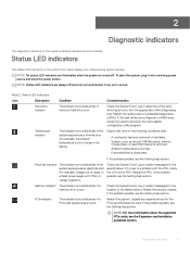
... the system and run embedded diagnostics (ePSA). Ensure that none of the failed memory. If it into a working power source and press the power button. NOTE: For more information about the supported PCIe cards, see the Getting help section. If the problem persists, ...Icon Description Condition Corrective action Hard drive indicator The indicator turns solid amber if there is out of range, or a failed power supply unit (PSU) or voltage regulator). 2 Diagnostic indicators The diagnostic indicators on the system indicates operation and error status. ...
... the system and run embedded diagnostics (ePSA). Ensure that none of the failed memory. If it into a working power source and press the power button. NOTE: For more information about the supported PCIe cards, see the Getting help section. If the problem persists, ...Icon Description Condition Corrective action Hard drive indicator The indicator turns solid amber if there is out of range, or a failed power supply unit (PSU) or voltage regulator). 2 Diagnostic indicators The diagnostic indicators on the system indicates operation and error status. ...
EMC PowerEdge Servers Troubleshooting Guide
Page 58
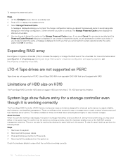
...power button for a storage controller even though it . HDD size has this reconditioning, you may see Starting and target RAID levels for enhanced performance, increased reliability, fault tolerance, and simplified management. During this limitation. If you choose to discard the cache, you are not supported on H310 The PowerEdge... RAID Controller H310 does not support HDD size more information about reconfiguration of the Dell EMC systems management solutions. Use a 6Gbps SAS HBA or an equivalent SAS...
...power button for a storage controller even though it . HDD size has this reconditioning, you may see Starting and target RAID levels for enhanced performance, increased reliability, fault tolerance, and simplified management. During this limitation. If you choose to discard the cache, you are not supported on H310 The PowerEdge... RAID Controller H310 does not support HDD size more information about reconfiguration of the Dell EMC systems management solutions. Use a 6Gbps SAS HBA or an equivalent SAS...
EMC PowerEdge Servers Troubleshooting Guide
Page 70
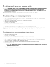
...Dell is not covered by a certified service technician. NOTE: After installing a power supply unit, allow several seconds for the system to deliver their rated capacity. The following sections provide information on troubleshooting power source and power supply units problems. Troubleshooting power source problems 1 Press the power button...that the system board is pressed, press the power button firmly. 2 Plug in another working properly. 3 If you have a redundant power supply configuration, ensure that are shipped with the Extended Power Performance (EPP) label on . For more ...
...Dell is not covered by a certified service technician. NOTE: After installing a power supply unit, allow several seconds for the system to deliver their rated capacity. The following sections provide information on troubleshooting power source and power supply units problems. Troubleshooting power source problems 1 Press the power button...that the system board is pressed, press the power button firmly. 2 Plug in another working properly. 3 If you have a redundant power supply configuration, ensure that are shipped with the Extended Power Performance (EPP) label on . For more ...
EMC PowerEdge Servers Troubleshooting Guide
Page 118
... SharePoint About this period, a message on by the system firmware and agents that monitor system components, see your system's Owner's manual at Dell.com/poweredgemanuals. c Press and hold the power button for 60 seconds to POST configuration is the config that the processors and heat sinks are unable to identify the defective part...
... SharePoint About this period, a message on by the system firmware and agents that monitor system components, see your system's Owner's manual at Dell.com/poweredgemanuals. c Press and hold the power button for 60 seconds to POST configuration is the config that the processors and heat sinks are unable to identify the defective part...

