
Getting Started Guide
Page 5
See "Using the System Setup Program" in four memory module sockets on the system board. • One of the following riser card options: - Intel® Celeron® - Intel Core 2 Duo™ - Quad-Core Intel Xeon Processor 3200 Series. • A minimum of 512 MB of ...Attached SCSI (SAS) hard drives with an optional SAS controller card. • Optional remote access controller for static rails and sliding rails. This option requires a riser card with a x4 lane capability. - Dual-Core Intel Xeon® Processor 3000 Series - One full-height, half-length, x8 lane PCIe expansion slot and...
See "Using the System Setup Program" in four memory module sockets on the system board. • One of the following riser card options: - Intel® Celeron® - Intel Core 2 Duo™ - Quad-Core Intel Xeon Processor 3200 Series. • A minimum of 512 MB of ...Attached SCSI (SAS) hard drives with an optional SAS controller card. • Optional remote access controller for static rails and sliding rails. This option requires a riser card with a x4 lane capability. - Dual-Core Intel Xeon® Processor 3000 Series - One full-height, half-length, x8 lane PCIe expansion slot and...
Getting Started Guide
Page 14
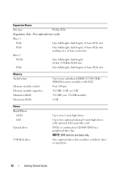
... One full-height, half-length, x8 lane PCIe slot PCIe One full-height, half-length, x4 lane PCIe slot residing on a x8 lane connector Riser 2 PCI-X One full-height, half-length, 64-bit, 133MHz PCI-X slot PCIe One full-height, half-length, x8 lane PCIe slot Memory Architecture Memory module ...
... One full-height, half-length, x8 lane PCIe slot PCIe One full-height, half-length, x4 lane PCIe slot residing on a x8 lane connector Riser 2 PCI-X One full-height, half-length, 64-bit, 133MHz PCI-X slot PCIe One full-height, half-length, x8 lane PCIe slot Memory Architecture Memory module ...

Hardware Owner's Manual (PDF)
Page 6
... Removing the Riser Card 79 Installing the Riser Card 80 System Memory 81 Memory Module Installation Guidelines 81 Installing Memory Modules 82 Removing Memory Modules 84 Processor 85 Replacing the Processor 85 Control ...
... Removing the Riser Card 79 Installing the Riser Card 80 System Memory 81 Memory Module Installation Guidelines 81 Installing Memory Modules 82 Removing Memory Modules 84 Processor 85 Replacing the Processor 85 Control ...

Hardware Owner's Manual (PDF)
Page 8
... Options 120 Viewing Information and Results 120 6 Jumpers and Connectors 121 System Board Jumpers 121 System Board Connectors 122 Riser Card Connectors 124 Disabling a Forgotten Password 125 7 Getting Help 127 Obtaining Assistance 127 Online Services 128 Automated Order-Status ...Service 129 Support Service 129 Dell Enterprise Training and Certification 129 Problems With Your Order 129 Product Information 129 Returning Items for Warranty Repair or Credit . . . . . 130 Before You Call 131 Contacting Dell 133 8 Contents
... Options 120 Viewing Information and Results 120 6 Jumpers and Connectors 121 System Board Jumpers 121 System Board Connectors 122 Riser Card Connectors 124 Disabling a Forgotten Password 125 7 Getting Help 127 Obtaining Assistance 127 Online Services 128 Automated Order-Status ...Service 129 Support Service 129 Dell Enterprise Training and Certification 129 Problems With Your Order 129 Product Information 129 Returning Items for Warranty Repair or Credit . . . . . 130 Before You Call 131 Contacting Dell 133 8 Contents

Hardware Owner's Manual (PDF)
Page 51
...; Cooling shroud • System battery • Optical drive • Hard drives • Fan assembly • Optional PCI fan • Power supply • Expansion cards • Riser card • System memory • Processor • Control panel • System board Recommended Tools You may need the following items to perform the procedures in...
...; Cooling shroud • System battery • Optical drive • Hard drives • Fan assembly • Optional PCI fan • Power supply • Expansion cards • Riser card • System memory • Processor • Control panel • System board Recommended Tools You may need the following items to perform the procedures in...
Hardware Owner's Manual (PDF)
Page 52
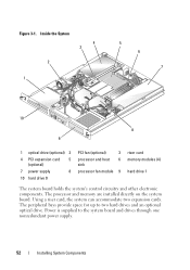
... drive (optional) 2 4 PCI expansion card 5 (optional) 7 power supply 8 10 hard drive 0 PCI fan (optional) 3 processor and heat 6 sink processor fan module 9 riser card memory modules (4) hard drive 1 The system board holds the system's control circuitry and other electronic components. Power is supplied to two hard drives and... an optional optical drive. Using a riser card, the system can accommodate two expansion cards. The processor and memory are installed directly on the system board....
... drive (optional) 2 4 PCI expansion card 5 (optional) 7 power supply 8 10 hard drive 0 PCI fan (optional) 3 processor and heat 6 sink processor fan module 9 riser card memory modules (4) hard drive 1 The system board holds the system's control circuitry and other electronic components. Power is supplied to two hard drives and... an optional optical drive. Using a riser card, the system can accommodate two expansion cards. The processor and memory are installed directly on the system board....

Hardware Owner's Manual (PDF)
Page 58
..."+" must face toward the open side of the System Setup screens. See "Using the System Setup Program" on page 56. 4 Remove the riser card. Before performing any of the components inside the computer and protecting against electrostatic discharge. 1 Enter the System Setup program and, if possible..., make a printed copy of the battery socket. 58 Installing System Components See "Removing the Riser Card" on page 79. 5 Locate the battery on page 54. 3 Remove the cooling shroud. See "Opening the System" on the system board. ...
..."+" must face toward the open side of the System Setup screens. See "Using the System Setup Program" on page 56. 4 Remove the riser card. Before performing any of the components inside the computer and protecting against electrostatic discharge. 1 Enter the System Setup program and, if possible..., make a printed copy of the battery socket. 58 Installing System Components See "Removing the Riser Card" on page 79. 5 Locate the battery on page 54. 3 Remove the cooling shroud. See "Opening the System" on the system board. ...

Hardware Owner's Manual (PDF)
Page 59
Replacing the Battery 1 2 3 1 battery 2 battery socket 3 retention tab 8 Reinstall the riser card. See "Closing the System" on page 106. Also, re-enter any system configuration information that the battery operates properly. 12 From the main screen, ... Battery" on page 55. 11 Enter the System Setup program to enter the correct time and date. Installing System Components 59 Figure 3-5. See "Installing the Riser Card" on page 57. 10 Close the system. See "Installing the Cooling Shroud" on page 80. 9 Install the cooling shroud.
Replacing the Battery 1 2 3 1 battery 2 battery socket 3 retention tab 8 Reinstall the riser card. See "Closing the System" on page 106. Also, re-enter any system configuration information that the battery operates properly. 12 From the main screen, ... Battery" on page 55. 11 Enter the System Setup program to enter the correct time and date. Installing System Components 59 Figure 3-5. See "Installing the Riser Card" on page 57. 10 Close the system. See "Installing the Cooling Shroud" on page 80. 9 Install the cooling shroud.
Hardware Owner's Manual (PDF)
Page 75
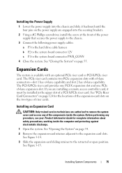
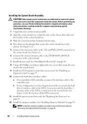
...and access any procedure, see your Product Information Guide for the locations of the expansion-card slots on the two types of a PCI-X/PCIe riser card. See Figure 3-14. 3 Slide the expansion-card sliding retainer to the expansion card slots. Expansion Cards The system is available with... Card CAUTION: Only trained service technicians are engaged into the chassis and slide it must be installed in the upper slot of riser cards. See "PCIe Riser Card Connectors" on page 54. 2 Remove the expansion-card retainer adjacent to the retracted or open position. Installing System Components ...
...and access any procedure, see your Product Information Guide for the locations of the expansion-card slots on the two types of a PCI-X/PCIe riser card. See Figure 3-14. 3 Slide the expansion-card sliding retainer to the expansion card slots. Expansion Cards The system is available with... Card CAUTION: Only trained service technicians are engaged into the chassis and slide it must be installed in the upper slot of riser cards. See "PCIe Riser Card Connectors" on page 54. 2 Remove the expansion-card retainer adjacent to the retracted or open position. Installing System Components ...

Hardware Owner's Manual (PDF)
Page 76
... keep dust and dirt out of the system and aid in order to the expansion card. See "Riser Card" on page 55. 76 Installing System Components NOTE: You may need to remove the expansion card... expansion-card bracket is also inserted into the expansion-card connector on the riser card until the card is fully seated. 4 Remove the filler bracket on the slot you need to remove the... riser card in proper cooling and airflow inside the system. 5 Insert the expansion card firmly into the securing...
... keep dust and dirt out of the system and aid in order to the expansion card. See "Riser Card" on page 55. 76 Installing System Components NOTE: You may need to remove the expansion card... expansion-card bracket is also inserted into the expansion-card connector on the riser card until the card is fully seated. 4 Remove the filler bracket on the slot you need to remove the... riser card in proper cooling and airflow inside the system. 5 Insert the expansion card firmly into the securing...

Hardware Owner's Manual (PDF)
Page 77
Figure 3-14. Installing and Removing Expansion Cards 1 2 3 5 1 expansion-card retainer 4 expansion-card connector (on riser card) 4 2 slot 1 5 expansion card 3 slot 2 Installing System Components 77
Figure 3-14. Installing and Removing Expansion Cards 1 2 3 5 1 expansion-card retainer 4 expansion-card connector (on riser card) 4 2 slot 1 5 expansion card 3 slot 2 Installing System Components 77

Hardware Owner's Manual (PDF)
Page 79
...precautions, working inside the computer and protecting against electrostatic discharge. 1 Open the system. See Figure 3-16. 4 Lift the riser card straight up and remove the riser card from the system. The brackets also keep dust and dirt out of the system and aid in proper cooling and airflow... empty card-slot opening. See "Opening the System" on page 78. 3 Using a #2 Phillips screwdriver, remove the two screws that secure the riser card to the chassis. See "Closing the System" on the expansion-card slots. Before performing any procedure, see your Product Information Guide for detailed ...
...precautions, working inside the computer and protecting against electrostatic discharge. 1 Open the system. See Figure 3-16. 4 Lift the riser card straight up and remove the riser card from the system. The brackets also keep dust and dirt out of the system and aid in proper cooling and airflow... empty card-slot opening. See "Opening the System" on page 78. 3 Using a #2 Phillips screwdriver, remove the two screws that secure the riser card to the chassis. See "Closing the System" on the expansion-card slots. Before performing any procedure, see your Product Information Guide for detailed ...

Hardware Owner's Manual (PDF)
Page 80
...system. See "Closing the System" on page 75. 4 Close the system. Figure 3-16. Installing and Removing the Riser Card 1 2 1 screws (2) 2 riser card Installing the Riser Card CAUTION: Only trained service technicians are authorized to the system board. 3 Install any of the components inside the ...and protecting against electrostatic discharge. 1 Insert the riser card firmly into the riser card connector on the system board until the riser card is fully seated. 2 Using a #2 Phillips screwdriver, install the two screws that secure the riser card to remove the system cover and access ...
...system. See "Closing the System" on page 75. 4 Close the system. Figure 3-16. Installing and Removing the Riser Card 1 2 1 screws (2) 2 riser card Installing the Riser Card CAUTION: Only trained service technicians are authorized to the system board. 3 Install any of the components inside the ...and protecting against electrostatic discharge. 1 Insert the riser card firmly into the riser card connector on the system board until the riser card is fully seated. 2 Using a #2 Phillips screwdriver, install the two screws that secure the riser card to remove the system cover and access ...

Hardware Owner's Manual (PDF)
Page 92
... chassis intrusion cable from the INTRUSION_SWITCH connector on the system board. 11 Disconnect the two power cables from the 12V and PWR_CONN connectors on the riser card. See Figure 6-2. 12 Pull up on the system board tray, slide the system board forward (toward the front of the system) and lift the... Card" on a smooth, nonconductive work surface. 92 Installing System Components See Figure 3-21. 14 Lay the system board tray down on page 78. 9 Remove the riser card.
... chassis intrusion cable from the INTRUSION_SWITCH connector on the system board. 11 Disconnect the two power cables from the 12V and PWR_CONN connectors on the riser card. See Figure 6-2. 12 Pull up on the system board tray, slide the system board forward (toward the front of the system) and lift the... Card" on a smooth, nonconductive work surface. 92 Installing System Components See Figure 3-21. 14 Lay the system board tray down on page 78. 9 Remove the riser card.
Hardware Owner's Manual (PDF)
Page 94
...two power cables to the 12V and PWR_CONN connectors on page 80. 8 Using a #2 Phillips screwdriver, tighten the two screws that secure the riser card to the system board. 9 Install any PCI expansion cards that you installed a SAS controller, reconnect the interface cable to the SATA_1 ...connector on page 82. See "Installing the Riser Card" on the system board. See "Replacing the Processor" on the system board. 7 Install the riser card. See Figure 6-2. 6 Connect the chassis intrusion cable to the INTRUSION_SWITCH connector on page...
...two power cables to the 12V and PWR_CONN connectors on page 80. 8 Using a #2 Phillips screwdriver, tighten the two screws that secure the riser card to the system board. 9 Install any PCI expansion cards that you installed a SAS controller, reconnect the interface cable to the SATA_1 ...connector on page 82. See "Installing the Riser Card" on the system board. See "Replacing the Processor" on the system board. 7 Install the riser card. See Figure 6-2. 6 Connect the chassis intrusion cable to the INTRUSION_SWITCH connector on page...
Hardware Owner's Manual (PDF)
Page 124
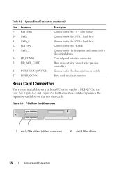
See Figure 6-3 and Figure 6-4 for the chassis intrusion switch Riser card interface connector Riser Card Connectors The system is available with either a PCIe riser card or a PCI-X/PCIe riser card. PCIe Riser Card Connectors 1 2 1 slot 1, PCIe x4-lane (x8-lane connector) 2 slot 2, PCIe x8-lane 124 Jumpers and Connectors Figure 6-3. Table 6-2. System Board Connectors (continued) Item... device Control panel interface connector Hard drive activity connector (expansion controller) Connector for the location and description of the expansion-card slots on the two riser cards.
See Figure 6-3 and Figure 6-4 for the chassis intrusion switch Riser card interface connector Riser Card Connectors The system is available with either a PCIe riser card or a PCI-X/PCIe riser card. PCIe Riser Card Connectors 1 2 1 slot 1, PCIe x4-lane (x8-lane connector) 2 slot 2, PCIe x8-lane 124 Jumpers and Connectors Figure 6-3. Table 6-2. System Board Connectors (continued) Item... device Control panel interface connector Hard drive activity connector (expansion controller) Connector for the location and description of the expansion-card slots on the two riser cards.

Hardware Owner's Manual (PDF)
Page 125
... the System" on page 55. 5 Reconnect the system to the electrical outlet, and turn on page 53. 3 Remove the password jumper plug. Figure 6-4. PCI-X/PCIe Riser Card Connectors 1 2 3 1 slot 1, PCI-X 64-bit 133 2 slot 2, PCIe x8-lane MHz (3.3 V) 3 system management Disabling a Forgotten Password The system's software security features include a system password...
... the System" on page 55. 5 Reconnect the system to the electrical outlet, and turn on page 53. 3 Remove the password jumper plug. Figure 6-4. PCI-X/PCIe Riser Card Connectors 1 2 3 1 slot 1, PCI-X 64-bit 133 2 slot 2, PCIe x8-lane MHz (3.3 V) 3 system management Disabling a Forgotten Password The system's software security features include a system password...
Hardware Owner's Manual (PDF)
Page 168
... file system structure. File transfer protocol. Gb - expansion-card connector - Gram(s). headless system - An unconditional format deletes all data stored on the system board or riser board for storing files. format - Feet.
... file system structure. File transfer protocol. Gb - expansion-card connector - Gram(s). headless system - An unconditional format deletes all data stored on the system board or riser board for storing files. format - Feet.
Hardware Owner's Manual (PDF)
Page 177
... external devices, 18 connectors riser card, 124 system board, 122 Console Redirection screen, 42 contacting Dell, 133 control panel installing, 90 removing, 89 cooling fan troubleshooting, 108 cooling shroud installing, 57 removing, 56 cover closing, 55 opening, 54 CPU Information screen, 39 D damaged systems troubleshooting, 105 Dell contacting, 133 Dell PowerEdge Diagnostics using, 117 Index...
... external devices, 18 connectors riser card, 124 system board, 122 Console Redirection screen, 42 contacting Dell, 133 control panel installing, 90 removing, 89 cooling fan troubleshooting, 108 cooling shroud installing, 57 removing, 56 cover closing, 55 opening, 54 CPU Information screen, 39 D damaged systems troubleshooting, 105 Dell contacting, 133 Dell PowerEdge Diagnostics using, 117 Index...
Hardware Owner's Manual (PDF)
Page 178
diagnostics advanced testing options, 119 running from the utility partition, 118 using Dell PowerEdge Diagnostics, 117 when to use, 118 diagnostics indicator codes, 29 drives CD, 60 optical, 60 features back-panel, 17 front-panel, 13 H hard drives configuring ... shroud, 57 expansion cards, 75 hard drives, 67 memory modules, 82 optical drive, 61 PCI fan assembly, 72 power supply, 75 processor fan assembly, 70 riser card, 80 system board, 94 Integrated Devices screen, 41 178 Index
diagnostics advanced testing options, 119 running from the utility partition, 118 using Dell PowerEdge Diagnostics, 117 when to use, 118 diagnostics indicator codes, 29 drives CD, 60 optical, 60 features back-panel, 17 front-panel, 13 H hard drives configuring ... shroud, 57 expansion cards, 75 hard drives, 67 memory modules, 82 optical drive, 61 PCI fan assembly, 72 power supply, 75 processor fan assembly, 70 riser card, 80 system board, 94 Integrated Devices screen, 41 178 Index


