
Getting Started Guide
Page 5
... memory modules in your system include: • 1U/1S rack-mountable chassis with support for remote systems management. Quad-Core Intel Xeon Processor 3200 Series. • A minimum of 512 MB of 667-MHz or 800-MHz DDR2 SDRAM memory, upgradable to view...for the following internal hard-drive configurations: - System Features The major hardware and software features of your Hardware Owner's Manual. • One of the following processors: - Intel Core 2 Duo™ - Up to two internal, 1-inch high optional Serial-Attached SCSI (SAS) hard drives with a x4 lane capability. -...
... memory modules in your system include: • 1U/1S rack-mountable chassis with support for remote systems management. Quad-Core Intel Xeon Processor 3200 Series. • A minimum of 512 MB of 667-MHz or 800-MHz DDR2 SDRAM memory, upgradable to view...for the following internal hard-drive configurations: - System Features The major hardware and software features of your Hardware Owner's Manual. • One of the following processors: - Intel Core 2 Duo™ - Up to two internal, 1-inch high optional Serial-Attached SCSI (SAS) hard drives with a x4 lane capability. -...

Getting Started Guide
Page 13
... your operating system. Be sure the operating system is installed before installing hardware or software not purchased with the system. Technical Specifications Processor Processor type Front-side bus speed Intel Celeron Intel Pentium Dual-Core Intel Core 2 Duo Dual-Core Intel Xeon 3000 Sequence Quad-Core ...Xeon 3200 Sequence One Intel® Celeron® processor or One Intel Core™ 2 Duo processor or One Intel Pentium® Dual-Core processor or Dual-Core Intel Xeon® 3000 Sequence processor or Quad-Core Intel Xeon 3200 Sequence processor 800 MHz minimum 800 MHz minimum 800 MHz ...
... your operating system. Be sure the operating system is installed before installing hardware or software not purchased with the system. Technical Specifications Processor Processor type Front-side bus speed Intel Celeron Intel Pentium Dual-Core Intel Core 2 Duo Dual-Core Intel Xeon 3000 Sequence Quad-Core ...Xeon 3200 Sequence One Intel® Celeron® processor or One Intel Core™ 2 Duo processor or One Intel Pentium® Dual-Core processor or Dual-Core Intel Xeon® 3000 Sequence processor or Quad-Core Intel Xeon 3200 Sequence processor 800 MHz minimum 800 MHz minimum 800 MHz ...

Hardware Owner's Manual (PDF)
Page 6
... Riser Card 79 Installing the Riser Card 80 System Memory 81 Memory Module Installation Guidelines 81 Installing Memory Modules 82 Removing Memory Modules 84 Processor 85 Replacing the Processor 85 Control Panel Assembly (Service-Only Procedure 89 Removing the Control Panel Assembly 89 Installing the Control Panel Assembly 90 System Board (Service...
... Riser Card 79 Installing the Riser Card 80 System Memory 81 Memory Module Installation Guidelines 81 Installing Memory Modules 82 Removing Memory Modules 84 Processor 85 Replacing the Processor 85 Control Panel Assembly (Service-Only Procedure 89 Removing the Control Panel Assembly 89 Installing the Control Panel Assembly 90 System Board (Service...
Hardware Owner's Manual (PDF)
Page 28
... drive. Ensure that came with your system. See "Memory Module Installation Guidelines" on page 127. 28 About Your System No micro code update loaded for processor 0 Micro code update failed. See the CDs that all memory modules are properly installed. See "Getting Help" on page 81. Table 1-4. If the problem persists...
... drive. Ensure that came with your system. See "Memory Module Installation Guidelines" on page 127. 28 About Your System No micro code update loaded for processor 0 Micro code update failed. See the CDs that all memory modules are properly installed. See "Getting Help" on page 81. Table 1-4. If the problem persists...
Hardware Owner's Manual (PDF)
Page 29
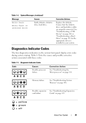
... expansion card failure. Corrective Action See "Troubleshooting the Microprocessor" on selected drive Causes Faulty diskette, diskette drive, hard drive. Diagnostic Indicator Codes Code Causes Possible processor failure. System Messages (continued) Message Write fault Write fault on page 114. A B C D Memory failure. Diagnostics Indicator Codes The four diagnostics indicators on page 113. = yellow...
... expansion card failure. Corrective Action See "Troubleshooting the Microprocessor" on selected drive Causes Faulty diskette, diskette drive, hard drive. Diagnostic Indicator Codes Code Causes Possible processor failure. System Messages (continued) Message Write fault Write fault on page 114. A B C D Memory failure. Diagnostics Indicator Codes The four diagnostics indicators on page 113. = yellow...
Hardware Owner's Manual (PDF)
Page 34
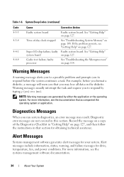
... may result. Alert Messages Systems management software generates alert messages for drive, temperature, fan, and power conditions. Table 1-6. See "Getting Help" on page 127. faulty processor See "Troubleshooting the Microprocessor" on the diskette. For example, before the system continues a task. NOTE: Warning messages are not covered in that accompanied the operating...
... may result. Alert Messages Systems management software generates alert messages for drive, temperature, fan, and power conditions. Table 1-6. See "Getting Help" on page 127. faulty processor See "Troubleshooting the Microprocessor" on the diskette. For example, before the system continues a task. NOTE: Warning messages are not covered in that accompanied the operating...
Hardware Owner's Manual (PDF)
Page 39
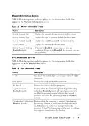
...the CPU Information screen. CPU Information Screen Option 64-bit Description Specifies if the installed processor supports Intel® 64-bit extensions. Enabled permits all logical processors to Disabled, the memory tests are conducted. Using the System Setup Program 39 Memory ...the operating system. Enabled permits virtualization software to Enabled, system memory tests are not performed. Displays the type of the processor. When set to be used by software that supports Virtualization Technology. When set to use Virtualization Technology incorporated in the ...
...the CPU Information screen. CPU Information Screen Option 64-bit Description Specifies if the installed processor supports Intel® 64-bit extensions. Enabled permits all logical processors to Disabled, the memory tests are conducted. Using the System Setup Program 39 Memory ...the operating system. Enabled permits virtualization software to Enabled, system memory tests are not performed. Displays the type of the processor. When set to be used by software that supports Virtualization Technology. When set to use Virtualization Technology incorporated in the ...
Hardware Owner's Manual (PDF)
Page 40
...State Tables are reported to the operating system. Displays the number of cores in Port X. Table 2-5. Displays the drive type of the processor. Enables or disables the hardware prefetcher. Displays the family and model number of the selected hard drive. Enables (Auto) or disables (...Off) the SATA hard drive in the processor. If the processor does not support Demand-Based Power Management, this option for applications that appear on the SATA Configuration screen. Displays the drive ...
...State Tables are reported to the operating system. Displays the number of cores in Port X. Table 2-5. Displays the drive type of the processor. Enables or disables the hardware prefetcher. Displays the family and model number of the selected hard drive. Enables (Auto) or disables (...Off) the SATA hard drive in the processor. If the processor does not support Demand-Based Power Management, this option for applications that appear on the SATA Configuration screen. Displays the drive ...

Hardware Owner's Manual (PDF)
Page 51
...; Optical drive • Hard drives • Fan assembly • Optional PCI fan • Power supply • Expansion cards • Riser card • System memory • Processor • Control panel • System board Recommended Tools You may need the following items to perform the procedures in this section: • Key to the...
...; Optical drive • Hard drives • Fan assembly • Optional PCI fan • Power supply • Expansion cards • Riser card • System memory • Processor • Control panel • System board Recommended Tools You may need the following items to perform the procedures in this section: • Key to the...
Hardware Owner's Manual (PDF)
Page 52
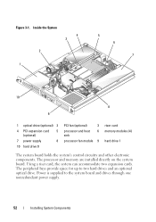
... accommodate two expansion cards. Inside the System 4 3 2 1 5 6 7 10 8 9 1 optical drive (optional) 2 4 PCI expansion card 5 (optional) 7 power supply 8 10 hard drive 0 PCI fan (optional) 3 processor and heat 6 sink processor fan module 9 riser card memory modules (4) hard drive 1 The system board holds the system's control circuitry and other electronic components. Figure 3-1. Power is supplied...
... accommodate two expansion cards. Inside the System 4 3 2 1 5 6 7 10 8 9 1 optical drive (optional) 2 4 PCI expansion card 5 (optional) 7 power supply 8 10 hard drive 0 PCI fan (optional) 3 processor and heat 6 sink processor fan module 9 riser card memory modules (4) hard drive 1 The system board holds the system's control circuitry and other electronic components. Figure 3-1. Power is supplied...

Hardware Owner's Manual (PDF)
Page 56
.... Removing the Cooling Shroud CAUTION: Only trained service technicians are authorized to these components and the system memory. Cooling Shroud The cooling shroud covers the processor and system battery and provides air flow to remove the system cover and access any procedure, see your Product Information Guide for complete information about...
.... Removing the Cooling Shroud CAUTION: Only trained service technicians are authorized to these components and the system memory. Cooling Shroud The cooling shroud covers the processor and system battery and provides air flow to remove the system cover and access any procedure, see your Product Information Guide for complete information about...
Hardware Owner's Manual (PDF)
Page 68
... the HDD0 cable from the SAS controller to hard drive 0 and attach the HDD1 cable to hard drive 1. See the controller card documentation for the processor and memory modules. 68 Installing System Components
... the HDD0 cable from the SAS controller to hard drive 0 and attach the HDD1 cable to hard drive 1. See the controller card documentation for the processor and memory modules. 68 Installing System Components

Hardware Owner's Manual (PDF)
Page 85
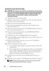
...56. 3 Using a #2 Phillips screwdriver, loosen the four captive screws that the processor might adhere to the heat sink and be removed from a processor unless you remove the heat sink while the processor is still warm. 2 Remove the cooling shroud. NOTICE: Never remove the heat sink... safety precautions, working inside the system. See "Removing the Cooling Shroud" on page 54. Installing System Components 85 Processor You can upgrade the processor to take advantage of the components inside the computer and protecting against electrostatic discharge. 1 Open the system. See Figure...
...56. 3 Using a #2 Phillips screwdriver, loosen the four captive screws that the processor might adhere to the heat sink and be removed from a processor unless you remove the heat sink while the processor is still warm. 2 Remove the cooling shroud. NOTICE: Never remove the heat sink... safety precautions, working inside the system. See "Removing the Cooling Shroud" on page 54. Installing System Components 85 Processor You can upgrade the processor to take advantage of the components inside the computer and protecting against electrostatic discharge. 1 Open the system. See Figure...

Hardware Owner's Manual (PDF)
Page 86
... lever upward to the fully open position so that the socket is ready for the heat sink to loosen from the processor. 5 If the heat sink has not separated from the processor, carefully rotate the heat sink in the open position. Do not pry the heat sink off of the... processor. 6 Lift the heat sink off of the socket. Leave the processor cover and release lever in a clockwise, then counterclockwise, direction until it releases from the processor. See Figure 3-19. 86 Installing System Components Installing and Removing the ...
... lever upward to the fully open position so that the socket is ready for the heat sink to loosen from the processor. 5 If the heat sink has not separated from the processor, carefully rotate the heat sink in the open position. Do not pry the heat sink off of the... processor. 6 Lift the heat sink off of the socket. Leave the processor cover and release lever in a clockwise, then counterclockwise, direction until it releases from the processor. See Figure 3-19. 86 Installing System Components Installing and Removing the ...

Hardware Owner's Manual (PDF)
Page 87
Installing and Removing the Processor 4 5 3 2 1 1 processor socket release lever 4 processor cover 2 processor socket 5 pin-1 locators 3 processor 10 Unpack the new processor. 11 Ensure that the processor is level in the socket to seat it in the fully open position. 12 Align the pin 1 corners of the processor and socket. See Figure 3-19. When the processor is in the socket. 14...
Installing and Removing the Processor 4 5 3 2 1 1 processor socket release lever 4 processor cover 2 processor socket 5 pin-1 locators 3 processor 10 Unpack the new processor. 11 Ensure that the processor is level in the socket to seat it in the fully open position. 12 Align the pin 1 corners of the processor and socket. See Figure 3-19. When the processor is in the socket. 14...

Hardware Owner's Manual (PDF)
Page 88
...this procedure. See Figure 3-18. 17 Install the cooling shroud. NOTE: Use the heat sink that secure the heat sink to verify that the processor information matches the new system configuration. d Using a #2 Phillips screwdriver, tighten in a diagonal pattern the four captive screws that you removed earlier in... the System Setup program. 19 Press to enter the System Setup program, and check that the new processor operates correctly. See "Closing the System" on page 35. 20 Run the system diagnostics to the system board. See Figure 3-18. See...
...this procedure. See Figure 3-18. 17 Install the cooling shroud. NOTE: Use the heat sink that secure the heat sink to verify that the processor information matches the new system configuration. d Using a #2 Phillips screwdriver, tighten in a diagonal pattern the four captive screws that you removed earlier in... the System Setup program. 19 Press to enter the System Setup program, and check that the new processor operates correctly. See "Closing the System" on page 35. 20 Run the system diagnostics to the system board. See Figure 3-18. See...

Hardware Owner's Manual (PDF)
Page 91
... Guide for complete information about safety precautions, working inside the system. See "Closing the System" on page 84. See "Replacing the Processor" on page 56. 3 Remove the heat sink and processor. See "Removing the Cooling Shroud" on page 85. 4 Remove the memory modules. Installing System Components 91 3 Connect the control panel cables...
... Guide for complete information about safety precautions, working inside the system. See "Closing the System" on page 84. See "Replacing the Processor" on page 56. 3 Remove the heat sink and processor. See "Removing the Cooling Shroud" on page 85. 4 Remove the memory modules. Installing System Components 91 3 Connect the control panel cables...
Hardware Owner's Manual (PDF)
Page 94
... expansion cards that the tabs on the chassis floor slide into the notches in step 3 of the SATA connectors. 11 Install the processor and heat sink. See "Replacing the Processor" on page 82. See Figure 6-2 for complete information about safety precautions, working inside the system. See "Installing Memory Modules" on page 85...
... expansion cards that the tabs on the chassis floor slide into the notches in step 3 of the SATA connectors. 11 Install the processor and heat sink. See "Replacing the Processor" on page 82. See Figure 6-2 for complete information about safety precautions, working inside the system. See "Installing Memory Modules" on page 85...
Hardware Owner's Manual (PDF)
Page 114
... Product Information Guide for the processor. Action CAUTION: Only trained service technicians are authorized to the electrical outlet, and turn on page 117. 2 Turn off the system and attached peripherals, and disconnect the system from the electrical outlet. 114 Troubleshooting Your System d Close the system. See "Using Dell PowerEdge Diagnostics" on the system...
... Product Information Guide for the processor. Action CAUTION: Only trained service technicians are authorized to the electrical outlet, and turn on page 117. 2 Turn off the system and attached peripherals, and disconnect the system from the electrical outlet. 114 Troubleshooting Your System d Close the system. See "Using Dell PowerEdge Diagnostics" on the system...

Hardware Owner's Manual (PDF)
Page 115
See "Opening the System" on page 85. 5 Close the system. Troubleshooting Your System 115 See "Replacing the Processor" on page 54. 4 Ensure that the processor and heat sink are properly installed. If the problem persists, see "Getting Help" on the system and attached peripherals. 3 Open the system. See "Closing the System" on page 55. 6 Reconnect the system to the electrical outlet, and turn on page 127.
See "Opening the System" on page 85. 5 Close the system. Troubleshooting Your System 115 See "Replacing the Processor" on page 54. 4 Ensure that the processor and heat sink are properly installed. If the problem persists, see "Getting Help" on the system and attached peripherals. 3 Open the system. See "Closing the System" on page 55. 6 Reconnect the system to the electrical outlet, and turn on page 127.


