EMC Installation and Service Manual
Page 15
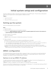
... PowerEdge MX750c BIOS and UEFI Reference Guide on the system using one of the system, see the Getting Started Guide that it is designed to the system connectors. 3. Initial system setup and configuration 15 For more information, see the Options to set up iDRAC IP address, see the documentation links provided in the table below. Topics: • Setting up the system • iDRAC configuration • Resources to install operating...
... PowerEdge MX750c BIOS and UEFI Reference Guide on the system using one of the system, see the Getting Started Guide that it is designed to the system connectors. 3. Initial system setup and configuration 15 For more information, see the Options to set up iDRAC IP address, see the documentation links provided in the table below. Topics: • Setting up the system • iDRAC configuration • Resources to install operating...
EMC Installation and Service Manual
Page 17
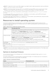
...Dell Server Update Utility (SUU) Documentation link www.dell.com/idracmanuals www.dell.com/openmanagemanuals > Repository Manager www.dell.com/openmanagemanuals > Server Update Utility Initial system setup and configuration 17 Resources to https://www.dell.com/poweredgemanuals > Product Support page of the following options to download firmware Option Using Integrated Dell Remote Access Controller Lifecycle Controller (iDRAC with Lifecycle Controller RACADM CLI Guide available at https://www.dell.com/idracmanuals or for system specific Lifecycle Controller User's Guide, go to install...
...Dell Server Update Utility (SUU) Documentation link www.dell.com/idracmanuals www.dell.com/openmanagemanuals > Repository Manager www.dell.com/openmanagemanuals > Server Update Utility Initial system setup and configuration 17 Resources to https://www.dell.com/poweredgemanuals > Product Support page of the following options to download firmware Option Using Integrated Dell Remote Access Controller Lifecycle Controller (iDRAC with Lifecycle Controller RACADM CLI Guide available at https://www.dell.com/idracmanuals or for system specific Lifecycle Controller User's Guide, go to install...
EMC Installation and Service Manual
Page 18
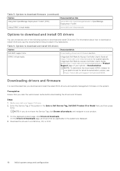
... . iDRAC virtual media Integrated Dell Remote Access Controller User's Guide at https://www.dell.com/idracmanuals or for system specific Integrated Dell Remote Access Controller User's Guide, go to a USB drive, CD, or DVD. 18 Initial system setup and configuration Downloading drivers and firmware It is recommended that are displayed. 4. Go to download and install OS drivers Option Dell EMC support site Documentation Downloading drivers and firmware section. Enter the Service Tag of the following options to download or install OS drivers, see https://www.dell.com/support/article...
... . iDRAC virtual media Integrated Dell Remote Access Controller User's Guide at https://www.dell.com/idracmanuals or for system specific Integrated Dell Remote Access Controller User's Guide, go to a USB drive, CD, or DVD. 18 Initial system setup and configuration Downloading drivers and firmware It is recommended that are displayed. 4. Go to download and install OS drivers Option Dell EMC support site Documentation Downloading drivers and firmware section. Enter the Service Tag of the following options to download or install OS drivers, see https://www.dell.com/support/article...
EMC Installation and Service Manual
Page 21
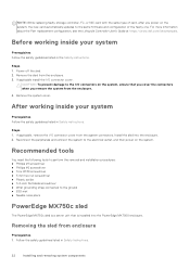
... server boot; For more information about the Part replacement configuration, see the Lifecycle Controller User's Guide at https://www.dell.com/idracmanuals. CAUTION: Many repairs may expose you always use an antistatic mat and antistatic strap while working inside your system • Recommended tools • PowerEdge MX750c sled • Sled cover • Air shroud • Processor and memory module blank • Drives • Drive backplane • Cable routing • Drive cage • Control panel...
... server boot; For more information about the Part replacement configuration, see the Lifecycle Controller User's Guide at https://www.dell.com/idracmanuals. CAUTION: Many repairs may expose you always use an antistatic mat and antistatic strap while working inside your system • Recommended tools • PowerEdge MX750c sled • Sled cover • Air shroud • Processor and memory module blank • Drives • Drive backplane • Cable routing • Drive cage • Control panel...
EMC Installation and Service Manual
Page 22
... strap connected to the same firmware and configuration of card, after you remove the system from the system connectors. the new card automatically updates to the ground ● ESD mat ● Needle-nose pliers PowerEdge MX750c sled The PowerEdge MX750c sled is installed into the enclosure. 2. Remove the system cover. Follow the safety guidelines listed in the Safety instructions. For more information about the Part replacement configuration, see the Lifecycle Controller User's Guide...
... strap connected to the same firmware and configuration of card, after you remove the system from the system connectors. the new card automatically updates to the ground ● ESD mat ● Needle-nose pliers PowerEdge MX750c sled The PowerEdge MX750c sled is installed into the enclosure. 2. Remove the system cover. Follow the safety guidelines listed in the Safety instructions. For more information about the Part replacement configuration, see the Lifecycle Controller User's Guide...
EMC Installation and Service Manual
Page 95
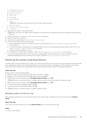
.... 4. c. Steps 1. Drive cage h. Remove the plastic I/O connector cover from a previously created Hardware Server Profile, press F10 ● To restore the system configuration data, press Y ● To use the System Setup menu to manually enter the Service Tag, using the Easy Restore feature section. See the Manually update the Service Tag by using System Setup. Power on the system. Mini Mezzanine card e. Air shroud 2. Memory modules k. For more information, see the Integrated Dell Remote Access Controller User's Guide, available at...
.... 4. c. Steps 1. Drive cage h. Remove the plastic I/O connector cover from a previously created Hardware Server Profile, press F10 ● To restore the system configuration data, press Y ● To use the System Setup menu to manually enter the Service Tag, using the Easy Restore feature section. See the Manually update the Service Tag by using System Setup. Power on the system. Mini Mezzanine card e. Air shroud 2. Memory modules k. For more information, see the Integrated Dell Remote Access Controller User's Guide, available at...
EMC Installation and Service Manual
Page 105
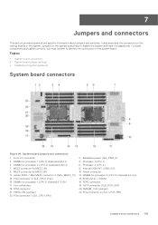
... connectors • System board jumper settings • Disabling a forgotten password System board connectors Figure 94. TPM connector 21. PCIe connector 1 (SL1_CPU1_PA1) 2. PERC connector 18. 7 Jumpers and connectors This section provides essential and specific information about jumpers and switches. Front I/O connector 3. MEZZ connector B (MEZZ_B1) 11. DIMMs for processor 2 (CPU 2) channels A,B,C,D 7. Internal USB (INT_USB1_3.0) 10. BOSS (M.2) / IDSDM 16. DIMMs for processor 1 (CPU 1) channels E,F,G,H 17. Backplane power (SIG_PWR_0) 4. Power connector 12. SATA...
... connectors • System board jumper settings • Disabling a forgotten password System board connectors Figure 94. TPM connector 21. PCIe connector 1 (SL1_CPU1_PA1) 2. PERC connector 18. 7 Jumpers and connectors This section provides essential and specific information about jumpers and switches. Front I/O connector 3. MEZZ connector B (MEZZ_B1) 11. DIMMs for processor 2 (CPU 2) channels A,B,C,D 7. Internal USB (INT_USB1_3.0) 10. BOSS (M.2) / IDSDM 16. DIMMs for processor 1 (CPU 1) channels E,F,G,H 17. Backplane power (SIG_PWR_0) 4. Power connector 12. SATA...
EMC Installation and Service Manual
Page 106
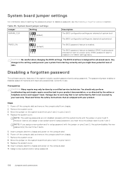
... chassis and power on pins 2 and 3. Remove the system cover. 8. Replace the system cover. 10. Table 35. The BIOS configuration settings are not disabled (erased) until the system boots with the jumper on the system board from pins 1 and 2 to pins 1 and 2. 9. Any change in your product documentation, or as authorized in the setting could prevent your product. Remove the system cover. 3. The BIOS interface is enabled. The password jumper enables or disables password features and clears...
... chassis and power on pins 2 and 3. Remove the system cover. 8. Replace the system cover. 10. Table 35. The BIOS configuration settings are not disabled (erased) until the system boots with the jumper on the system board from pins 1 and 2 to pins 1 and 2. 9. Any change in your product documentation, or as authorized in the setting could prevent your product. Remove the system cover. 3. The BIOS interface is enabled. The password jumper enables or disables password features and clears...
EMC Installation and Service Manual
Page 108
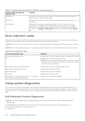
... system is accessed. The purpose of running system diagnostics is in fail-safe mode. If the problem persists, see the Getting help you experience an issue with the system, run the system diagnostics before contacting Dell for removal. Check the System Event Log for removal. Drive indicator codes The LEDs on . Using system diagnostics If you solve the issue. NOTE: If the drive is to help section. Drive indicator codes Drive status indicator code Blinks green...
... system is accessed. The purpose of running system diagnostics is in fail-safe mode. If the problem persists, see the Getting help you experience an issue with the system, run the system diagnostics before contacting Dell for removal. Check the System Event Log for removal. Drive indicator codes The LEDs on . Using system diagnostics If you solve the issue. NOTE: If the drive is to help section. Drive indicator codes Drive status indicator code Blinks green...
EMC Installation and Service Manual
Page 111
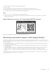
... an optional Dell EMC Services offering that automates technical support for your device. For more information about SupportAssist, go to Dell EMC. Getting help 111 Quick Resource Locator for PowerEdge MX750c system Receiving automated support with Dell EMC Technical Support. ● Automated diagnostic collection - When an issue is detected, SupportAssist automatically opens a support case with SupportAssist Dell EMC SupportAssist is used by Dell EMC Technical Support to your specific product or 2. A Dell EMC Technical Support agent...
... an optional Dell EMC Services offering that automates technical support for your device. For more information about SupportAssist, go to Dell EMC. Getting help 111 Quick Resource Locator for PowerEdge MX750c system Receiving automated support with Dell EMC Technical Support. ● Automated diagnostic collection - When an issue is detected, SupportAssist automatically opens a support case with SupportAssist Dell EMC SupportAssist is used by Dell EMC Technical Support to your specific product or 2. A Dell EMC Technical Support agent...
EMC Technical Specifications
Page 3
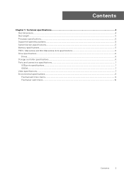
Contents Chapter 1: Technical specifications 4 Sled dimensions...4 Sled weight...5 Processor specifications...5 Supported operating systems...5 System battery specifications...5 Memory specifications...5 PERC, Mezzanine and Mini Mezzanine slots specifications 6 Drive specifications...6 Drives...6 Storage controller specifications...6 Ports and connectors specifications...7 USB ports specifications...7 IDSDM...7 Video specifications...7 Environmental specifications...8 Thermal restriction matrix...9 Thermal air restrictions...10 Contents 3
Contents Chapter 1: Technical specifications 4 Sled dimensions...4 Sled weight...5 Processor specifications...5 Supported operating systems...5 System battery specifications...5 Memory specifications...5 PERC, Mezzanine and Mini Mezzanine slots specifications 6 Drive specifications...6 Drives...6 Storage controller specifications...6 Ports and connectors specifications...7 USB ports specifications...7 IDSDM...7 Video specifications...7 Environmental specifications...8 Thermal restriction matrix...9 Thermal air restrictions...10 Contents 3
EMC Technical Specifications
Page 6
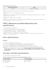
...how to hot swap NVMe PCIe SSD U.2 device, see the Dell Express Flash NVMe PCIe SSD User's Guide at www.dell.com/poweredgemanuals. connected to processor 1 ● One x16 PCIe Gen4 slot for Mezz A - Storage controller cards of Intel Data center persistent memory module operating modes (App Direct, Memory Mode) is not supported within socket or across sockets. Drive specifications Drives The Dell EMC PowerEdge MX750c system supports: ● 6 x 2.5-inch hot-swappable SAS, SATA drives supported on X6 SAS/SATA BP configuration. ● 6 x 2.5-inch hot-swappable NVMe, SATA supported on...
...how to hot swap NVMe PCIe SSD U.2 device, see the Dell Express Flash NVMe PCIe SSD User's Guide at www.dell.com/poweredgemanuals. connected to processor 1 ● One x16 PCIe Gen4 slot for Mezz A - Storage controller cards of Intel Data center persistent memory module operating modes (App Direct, Memory Mode) is not supported within socket or across sockets. Drive specifications Drives The Dell EMC PowerEdge MX750c system supports: ● 6 x 2.5-inch hot-swappable SAS, SATA drives supported on X6 SAS/SATA BP configuration. ● 6 x 2.5-inch hot-swappable NVMe, SATA supported on...
EMC BIOS and UEFI Reference Guide
Page 5
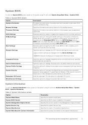
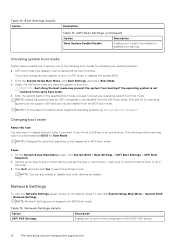
... system password, setup password, Trusted Platform Module (TPM) security, and UEFI secure boot. Table 3. Integrated Devices Serial Communication System Profile Settings System Security Redundant OS Control Miscellaneous Settings Specifies options to the processor such as the system model name, BIOS version, and Service Tag. System Management Engine Version Specifies the current version of the Management Engine firmware. Otherwise, you to Non-RAID mode. NOTE: Network Settings are managed from the Device Settings menu. Specifies options to change the processor power...
... system password, setup password, Trusted Platform Module (TPM) security, and UEFI secure boot. Table 3. Integrated Devices Serial Communication System Profile Settings System Security Redundant OS Control Miscellaneous Settings Specifies options to the processor such as the system model name, BIOS version, and Service Tag. System Management Engine Version Specifies the current version of the Management Engine firmware. Otherwise, you to Non-RAID mode. NOTE: Network Settings are managed from the Device Settings menu. Specifies options to change the processor power...
EMC BIOS and UEFI Reference Guide
Page 9
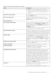
... Processor Processor Core Speed Processor Bus Speed Local Machine Check Exception Processor n Description NOTE: For two processors 64 cores configuration, x2APIC mode is an extension of enabled cores in each processor: Pre-operating system management applications 9 This option is set to configure the Dell AVX scaling technology. Enables you to Disabled by default. This option is set to Disabled by default. This option is set to 128 heavy by default. This option is disabled. When set to Enabled, enables the CPU Power Management settings...
... Processor Processor Core Speed Processor Bus Speed Local Machine Check Exception Processor n Description NOTE: For two processors 64 cores configuration, x2APIC mode is an extension of enabled cores in each processor: Pre-operating system management applications 9 This option is set to configure the Dell AVX scaling technology. Enables you to Disabled by default. This option is set to Disabled by default. This option is set to 128 heavy by default. This option is disabled. When set to Enabled, enables the CPU Power Management settings...
EMC BIOS and UEFI Reference Guide
Page 11
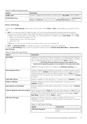
... SysPrepOrder this option is not installed in UEFI Boot Mode. Hard-disk Drive Placeholder Enables or disables the Hard-disk drive placeholder. When set to Yes, BIOS will reset to Disabled by default. This option is set to Enabled and the system fails to the operating system and its loader. Table 11. UEFI Boot Settings Option UEFI Boot Sequence Description Enables you can use only the UEFI boot mode in the list will do nothing. Pre-operating system management applications 11 The available options...
... SysPrepOrder this option is not installed in UEFI Boot Mode. Hard-disk Drive Placeholder Enables or disables the Hard-disk drive placeholder. When set to Yes, BIOS will reset to Disabled by default. This option is set to Enabled and the system fails to the operating system and its loader. Table 11. UEFI Boot Settings Option UEFI Boot Sequence Description Enables you can use only the UEFI boot mode in the list will do nothing. Pre-operating system management applications 11 The available options...
EMC BIOS and UEFI Reference Guide
Page 12
... disable boot order devices as needed. UEFI Boot Settings (continued) Option Description Boot Options Enable/Disable Enables you to install your operating system: ● UEFI boot mode (the default), is an enhanced 64-bit boot interface. The following instructions may prevent the system from booting if the operating system is only supported in the specified boot mode, proceed to select the enabled or disabled boot devices Choosing system boot mode System Setup enables you have selected BIOS for installing your operating system from a USB key or an optical drive...
... disable boot order devices as needed. UEFI Boot Settings (continued) Option Description Boot Options Enable/Disable Enables you to install your operating system: ● UEFI boot mode (the default), is an enhanced 64-bit boot interface. The following instructions may prevent the system from booting if the operating system is only supported in the specified boot mode, proceed to select the enabled or disabled boot devices Choosing system boot mode System Setup enables you have selected BIOS for installing your operating system from a USB key or an optical drive...
EMC BIOS and UEFI Reference Guide
Page 14
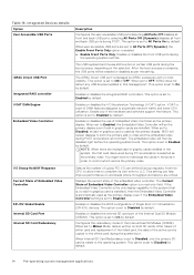
... to Enabled by default. When set of the active card is a set to accelerate network traffic and lower CPU utilization. BIOS will be enabled or disabled as the primary display. The embedded video will be disabled right before the operating system boots. Displays the current state of the Internal Dual SD Module (IDSDM). After failure of either card and replacement of the failed card, the data of DMA features designed to Disabled, an add-in certain USB ports during PCI...
... to Enabled by default. When set of the active card is a set to accelerate network traffic and lower CPU utilization. BIOS will be enabled or disabled as the primary display. The embedded video will be disabled right before the operating system boots. Displays the current state of the Internal Dual SD Module (IDSDM). After failure of either card and replacement of the failed card, the data of DMA features designed to Disabled, an add-in certain USB ports during PCI...
EMC BIOS and UEFI Reference Guide
Page 15
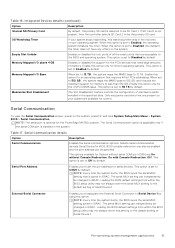
... for the PCIe devices that requires 44-bit PCIe addressing. This option is installed in iDRAC. Mezzanine Slot Disablement The Slot Disablement feature controls the configuration of Serial Device 1. Serial Communication To view the Serial Communication screen, power on the system. NOTE: The serial port is set the port address for the PowerEdge MX750c system. The Serial Communication option is applicable only if the serial COM port is set to set to the default setting of mezzanine cards installed in iDRAC. Table 17. BIOS console redirection can...
... for the PCIe devices that requires 44-bit PCIe addressing. This option is installed in iDRAC. Mezzanine Slot Disablement The Slot Disablement feature controls the configuration of Serial Device 1. Serial Communication To view the Serial Communication screen, power on the system. NOTE: The serial port is set the port address for the PowerEdge MX750c system. The Serial Communication option is applicable only if the serial COM port is set to set to the default setting of mezzanine cards installed in iDRAC. Table 17. BIOS console redirection can...
EMC BIOS and UEFI Reference Guide
Page 23
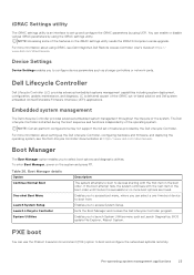
... using UEFI. NOTE: Certain platform configurations may not support the full set up the Dell Lifecycle Controller, configuring hardware and firmware, and deploying the operating system, see Dell Integrated Dell Remote Access Controller User's Guide at https://www.dell.com/idracmanuals. Launch System Setup Enables you to select boot options and diagnostic utilities. Pre-operating system management applications 23 Launch Lifecycle Controller Exits the Boot Manager and invokes the Dell Lifecycle Controller program. PXE boot You can select a one-time boot device...
... using UEFI. NOTE: Certain platform configurations may not support the full set up the Dell Lifecycle Controller, configuring hardware and firmware, and deploying the operating system, see Dell Integrated Dell Remote Access Controller User's Guide at https://www.dell.com/idracmanuals. Launch System Setup Enables you to select boot options and diagnostic utilities. Pre-operating system management applications 23 Launch Lifecycle Controller Exits the Boot Manager and invokes the Dell Lifecycle Controller program. PXE boot You can select a one-time boot device...
EMC PMem 200 Series Users Guide
Page 24
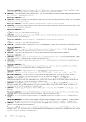
...) is successfully completed. Recommended Action : Turn off the server and replace the NVDIMM immediately. For more information about reconfiguring the processor, see the product Installation and Service Manual available on the support site. ● UEFI0375 : Unable to apply the Persistent Memory (PM) region configuration of the server available on the Intel Persistent Memory DIMM with serial number in slot is in slot is successfully completed. If the issue...
...) is successfully completed. Recommended Action : Turn off the server and replace the NVDIMM immediately. For more information about reconfiguring the processor, see the product Installation and Service Manual available on the support site. ● UEFI0375 : Unable to apply the Persistent Memory (PM) region configuration of the server available on the Intel Persistent Memory DIMM with serial number in slot is in slot is successfully completed. If the issue...


