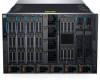
EMC PowerEdge Servers Troubleshooting Guide
Page 3
... Quick Sync 2 indicator codes...11 iDRAC Direct LED indicator codes...12 NIC indicator codes...12 Power supply unit indicator codes...13 Non-redundant power supply unit indicator codes...14 Hard drive indicator codes...15 uSATA SSD indicator codes...16 Internal dual...Troubleshooting iDRAC Direct - Laptop connection 40 Troubleshooting a serial Input Output device...40 Troubleshooting a NIC...41 NIC teaming on a PowerEdge Server...41 Troubleshooting a wet system...41 Troubleshooting a damaged system...42 Troubleshooting the system battery...43 Troubleshooting cooling problems...43 Troubleshooting...
EMC PowerEdge Servers Troubleshooting Guide
Page 4
... problems...60 Troubleshooting power supply unit problems...60 Troubleshooting RAID...60 RAID configuration using PERC...60 RAID configuration using OpenManage Server Administrator 63 RAID configuration by using Unified Server Configurator 67 Downloading and installing the RAID controller log export by using PERCCLI tool on ESXi hosts on Dell's 13th generation of PowerEdge servers...69...
EMC PowerEdge Servers Troubleshooting Guide
Page 7
...power supply unit: • AMP 90871-1 hand-crimping tool or equivalent • Tyco Electronics 58433-3 or equivalent • Wire-stripper pliers to correct them. To view the document that are frequently encountered or are responsible for managing the Dell PowerEdge servers, however might occur on Dell PowerEdge servers, however focuses on the Dell PowerEdge... tasks on issues that is listed in this guide to learn how to identify and troubleshoot the Dell PowerEdge server issues. In particular, this guide: • Provides troubleshooting procedures for issues related to Server...
EMC PowerEdge Servers Troubleshooting Guide
Page 10
... the ambient temperature is out of the failed memory. Reseat the memory module. If it into a working power source and press the power button. If the a failed power supply unit (PSU) or problem persists, see the Getting help section. Check the System Event Log to a problem...8226; iDRAC Quick Sync 2 indicator codes • iDRAC Direct LED indicator codes • NIC indicator codes • Power supply unit indicator codes • Non-redundant power supply unit indicator codes • Hard drive indicator codes • uSATA SSD indicator codes • Internal dual SD module indicator...
EMC PowerEdge Servers Troubleshooting Guide
Page 13
...and activity is off When hot-plugging a PSU, the PSU handle blinks green five times at a rate of PowerEdge servers is not supported, even if the PSUs have the same power rating. NIC identify is being sent or received. Figure 4. Blinking green and turns off Condition The NIC is .... The NIC is connected to a low output configuration or vice versa, you must have an LED that serves as an indicator. Power supply unit indicator codes AC power supply units (PSUs) have an illuminated translucent handle that serves as an indicator and DC PSUs have the same type of Titanium PSUs, ...
EMC PowerEdge Servers Troubleshooting Guide
Page 14
... system. 14 Diagnostic indicators AC PSU status indicator (continued) Power indicator codes Condition CAUTION: If two PSUs are used , they must be of the same type and have the same maximum output power. Non-redundant power supply unit indicator codes Press the self-diagnostic button to perform a... quick health check on the non-redundant power supply unit (PSU) of the same type and have the same maximum output...
EMC PowerEdge Servers Troubleshooting Guide
Page 38
...; Troubleshooting an optical drive • Troubleshooting a tape backup unit • Troubleshooting no bootable device found Troubleshooting a no power issues • Troubleshooting power supply units • Troubleshooting RAID • Troubleshooting thermal issue • Input/Output errors while reseating SAS IOM storage sled on... Dell Technical Support for assistance. For all the cables of hard drive backplane at both ends. 5. Reseat all other startup issues, note the system messages that appear on the screen. To avoid this issue, you must boot to the server's power supply units...
EMC PowerEdge Servers Troubleshooting Guide
Page 42
... system starts properly, turn off the system, and reinstall all the expansion cards that the following components (if installed) from the system: • Power supply unit(s) • Optical drive • Hard drives • Hard drive backplane • USB memory key • Hard drive tray • ... your product documentation, or as directed by a certified service technician. Read and follow the safety instructions that is not authorized by Dell is not covered by your product. Turn off the system and attached peripherals, and disconnect the system from the electrical outlet. 2....
EMC PowerEdge Servers Troubleshooting Guide
Page 59
... Run the appropriate diagnostic test. The following steps to servicing that is not authorized by Dell is properly installed: a. Remove the system cover. Troubleshooting no power issues Prerequisites Ensure all power supplies are firmly seated, power cables are connected, and both power supplies are shipped with your product. You should only perform troubleshooting and simple repairs as...
EMC PowerEdge Servers Troubleshooting Guide
Page 60
... Lifecycle Controller User's Guide available at www.dell.com/ poweredgemanuals. Ensure that both the power supply units are no loose connections exist. Troubleshooting power source problems Steps 1. Ensure that you have to upgrade to ensure that the power supply is pressed, press the power button firmly. 2. Ensure that the power supply handle LED indicates that your system has one...
EMC PowerEdge Servers Troubleshooting Guide
Page 104
... POST, plug the hard drives back one at qrl.dell.com. 2. If you identify the defective part, contact Dell Technical Support with information about the event and error messages generated by verifying that the processors and heat sinks are found . Ensure that the power supply LED glows green. For more information , see the Error...
EMC PowerEdge RAID Controller S140 Users Guide
Page 43
... PCIe SSDs during the OS installation using Dell LifeCycle controller, then the physical disk write cache policy is recommended). After enabling Hypervisor, system displays Blue Screen of virtual disks exceeds than 30. OS installation failing on a server. Use OpenManage to ensure that there is constant power supply to the system (A UPS is set...
Event and Error Message Reference Guide for EMC PowerEdge Servers
Page 4
...Dell Enterprise systems. • Messages are prefixed with event type to resolve an issue. and software categories in the server and its management applications (such as a result of each message is listed in the log files. For example PSU, STOR, and VLT representing power supply... Boot control Cable Chassis Management Control Processor Proc Absent Storage Controller Certificate Management Diagnostic Auto-discovery Dell Key Manager Storage enclosure Extended power performance Fan event Fibre channel Feature card Unknown Debug 4 Introduction Messages are displayed or stored as...
Event and Error Message Reference Guide for EMC PowerEdge Servers
Page 5
... Controller Licensing Link status Log event Memory NIC configuration OS deployment OS event PCI device Physical disk drive System performance event Power usage Part exchange BIOS POST Power supply unit PSU absent Power usage RAC event Redundancy FW download IDSDM media IDSDM absent Flex address SD IDSDM redundancy Remote service Security event System event...
EMC PowerEdge MX7000 Enclosure Installation and Service Manual
Page 3
Contents 1 About this document...6 2 Next Generation Modular overview 7 PowerEdge MX architecture overview...10 3 Enclosure overview...11 Front view of the enclosure...12 Control panel...12 PSU indicators...15 Fan module indicator codes...15 Back ... 31 Cooling fan modules...33 Removing a front fan module...33 Installing a front fan module...33 Removing a rear fan module...34 Installing a rear fan module...35 Power supply units ...35 Contents 3
EMC PowerEdge MX7000 Enclosure Installation and Service Manual
Page 4
...power supply unit...36 Acoustic baffle...37 Removing the air baffle...37 Installing the air baffle...38 Fabrics and modules...39 Removing a blank from Fabric A or B slot...39 Installing a blank in Fabric A or B slot...39 Removing a module from Fabric A or B slot...40 Installing a module in Fabric A or B slot...41 Removing a MX7000...specifications...53 Ports and connectors specifications...53 USB ports...53 Mini DisplayPort...53 PowerEdge MX modules ports and connectors...54 PowerEdge MX740c...54 PowerEdge MX840c...54 MX7116n Fabric Expander Module...54 MX9116n Fabric Switching Engine...54 ...
EMC PowerEdge MX7000 Enclosure Installation and Service Manual
Page 11
... must be populated in the enclosure. Up to seven Storage sleds can be mapped to a storage node. • Up to six hot swappable power supply units. • Up to two hot swappable management modules. • Up to six I/O modules: ○ Four Fabric-A/B type IOMs ○... fans. • Five rear accessible hot swappable cooling fans. For more information about dual management modules, see Technical specifications. The PowerEdge MX7000 enclosure is the next-generation M1000e follow-on chassis and a revolutionary architecture set to be the future foundation of your system Enclosure ...
EMC PowerEdge MX7000 Enclosure Installation and Service Manual
Page 12
Left control panel 3. Right control panel 9. Status LED 12 Enclosure overview Front view of the enclosure Figure 3. Sled blank 5. Power supply unit (6) Control panel Left control panel 2. Single-width storage sled 8. Double-width compute sled 7. Left control panel - Front fan (4) 6. Information tag Figure 4. Front view of the enclosure 1. Single-width compute sled 4.
EMC PowerEdge MX7000 Enclosure Installation and Service Manual
Page 26
...proper operation and cooling for all the sleds, module bays, power supply units, and system fans must be done by yourself. Power off the enclosure. 4. For more information, see the Rack Installation Guide at www.dell.com/poweredgemanuals. WARNING: Opening or removing the cover while the...the electrical outlet. 5. Remove the enclosure from the rack. For more information, see the Rack Installation Guide at www.dell.com/poweredgemanuals. 2. Power on may only be populated with your warranty. Reconnect the sleds, and the peripherals into the rack, if removed. Connect...
EMC PowerEdge MX7000 Enclosure Installation and Service Manual
Page 27
... button to install a sled blank in all the empty bays. Installing and removing system components 27 Non-hot plug devices Main distribution board Vertical power distribution board Rear fan board Left and right control panels Storage and compute sleds Removing a sled blank Prerequisites 1. Operating the enclosure without a blank... results in Safety instructions. Hot plug and Non-hot plug devices Table 10. Hot plug devices Hot plug devices Cooling fans Power supply units Management services modules Fabric A/ B/ C input output modules Sleds NOTE: Ensure that the sled is...