
Glossary
Page 1
... thermal unit. Celsius. Certificate authority. Ampere(s). Advanced Configuration and Power Interface. American National Standards Institute. blade - Baseboard management controller. Your system also contains an address bus and a data bus for developing technology standards in the U.S. Dell™ Glossary NOTE: For additional information on storage terminology, visit the Storage Networking Industry Association's website...
... thermal unit. Celsius. Certificate authority. Ampere(s). Advanced Configuration and Power Interface. American National Standards Institute. blade - Baseboard management controller. Your system also contains an address bus and a data bus for developing technology standards in the U.S. Dell™ Glossary NOTE: For additional information on storage terminology, visit the Storage Networking Industry Association's website...

Information Update
Page 5
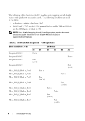
...Module Port Mapping (Quad-Port Mezzanine Cards) The following table, n denotes a variable value from 1 to 16. PowerEdge Blades - Table 1-1. In the following table illustrates the I/O module port mapping for a half-height blade with the quad-port mezzanine card. I /O Module B1 C1 C2 B2 A2 Port n Port n Port n... Port (n+16) Port (n+16) Port n Port n Port (n+16) Port (n+16) Information Update 5 NOTE: For a detailed mapping of each PowerEdge system, see the document ...
...Module Port Mapping (Quad-Port Mezzanine Cards) The following table, n denotes a variable value from 1 to 16. PowerEdge Blades - Table 1-1. In the following table illustrates the I/O module port mapping for a half-height blade with the quad-port mezzanine card. I /O Module B1 C1 C2 B2 A2 Port n Port n Port n... Port (n+16) Port (n+16) Port n Port n Port (n+16) Port (n+16) Information Update 5 NOTE: For a detailed mapping of each PowerEdge system, see the document ...
Information Update
Page 6
Table 1-2. I/O Module Port Assignments-Full-Height Blades Blade n and Blade (n + 8) I /O module port mapping for full-height blades with quad-port mezzanine cards. The following table illustrates the I /O Module A1 B1 C1 C2 B2 A2 Integrated LOM1 Port n Integrated LOM2 Port n ... used in the table: • n denotes a variable value from 1 to 8 • LOM1 and LOM2 are the LOM ports of blade n and LOM3 and LOM4 are the LOM ports of blade (n+8) NOTE: For a detailed mapping of each PowerEdge system, see the document Quadport Capable Hardware For the M1000e Modular Chassis on support...
Table 1-2. I/O Module Port Assignments-Full-Height Blades Blade n and Blade (n + 8) I /O module port mapping for full-height blades with quad-port mezzanine cards. The following table illustrates the I /O Module A1 B1 C1 C2 B2 A2 Integrated LOM1 Port n Integrated LOM2 Port n ... used in the table: • n denotes a variable value from 1 to 8 • LOM1 and LOM2 are the LOM ports of blade n and LOM3 and LOM4 are the LOM ports of blade (n+8) NOTE: For a detailed mapping of each PowerEdge system, see the document Quadport Capable Hardware For the M1000e Modular Chassis on support...

Information Update
Page 7
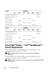
Table 1-2. I/O Module Port Assignments-Full-Height Blades (continued) Blade n and Blade (n + 8) I/O Module A1 B1 C1 C2 B2 A2 Mezz_FAB_B_Blade n+8_Port1 Port (n+8) Mezz_FAB_B_Blade n+8_Port2 Port (n+8) Mezz_FAB_B_Blade n+8_Port3 Port (n+24) Mezz_FAB_B_Blade n+8_Port4 Port (n+24) Mezz_FAB_C_Blade n+8_Port1 Port (n+8) Mezz_FAB_C_Blade n+8_Port2 Port (n+8) Mezz_FAB_C_Blade n+8_Port3 Port (n+24) Mezz_FAB_C_Blade n+8_Port4 Port (n+24) Information Update 7
Table 1-2. I/O Module Port Assignments-Full-Height Blades (continued) Blade n and Blade (n + 8) I/O Module A1 B1 C1 C2 B2 A2 Mezz_FAB_B_Blade n+8_Port1 Port (n+8) Mezz_FAB_B_Blade n+8_Port2 Port (n+8) Mezz_FAB_B_Blade n+8_Port3 Port (n+24) Mezz_FAB_B_Blade n+8_Port4 Port (n+24) Mezz_FAB_C_Blade n+8_Port1 Port (n+8) Mezz_FAB_C_Blade n+8_Port2 Port (n+8) Mezz_FAB_C_Blade n+8_Port3 Port (n+24) Mezz_FAB_C_Blade n+8_Port4 Port (n+24) Information Update 7
Information Update
Page 8
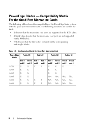
PowerEdge Blades - Configuration Matrix for the corresponding half-height blades. Compatibility Matrix For the Quad-Port Mezzanine Cards The following notations are used in the table. • X denotes... card ports are not supported on the IOM fabric. • N/A denotes that the fabric does not exist for Quad-Port Mezzanine Card PowerEdge Blade Fabric B1 Port 1 Port 3 and 2 and 4 M710 X X M905 X X M805 X X M605 X X M610 X X M600 X X Fabric C1 Port 1 and 2 X Port 3 and 4 X X X X X Fabric B2 Port 1 and 2 X X X N/A N/A N/A Port 3 and 4 X X X N/A N/A N/A ...
PowerEdge Blades - Configuration Matrix for the corresponding half-height blades. Compatibility Matrix For the Quad-Port Mezzanine Cards The following notations are used in the table. • X denotes... card ports are not supported on the IOM fabric. • N/A denotes that the fabric does not exist for Quad-Port Mezzanine Card PowerEdge Blade Fabric B1 Port 1 Port 3 and 2 and 4 M710 X X M905 X X M805 X X M605 X X M610 X X M600 X X Fabric C1 Port 1 and 2 X Port 3 and 4 X X X X X Fabric B2 Port 1 and 2 X X X N/A N/A N/A Port 3 and 4 X X X N/A N/A N/A ...
Information Update
Page 9
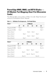
... Integrated LOM2 Mezz1_Fab_C Mezz2_Fab_B Mezz3_Fab_C Mezz4_Fab_B A1 Port 1 Port 9 B1 Port 1 Port 9 I/O Module C1 C2 Port 1 Port 1 Port 9 Port 9 B2 Port 1 Port 9 A2 Port 1 Port 9 Blade 4 Integrated LOM1 Integrated LOM2 Mezz1_Fab_C Mezz2_Fab_B Mezz3_Fab_C Mezz4_Fab_B I /O Module Port Mapping (Dual-Port Mezzanine Cards) The following tables correct portions of Table 1-12 in the... B1 C1 C2 B2 A2 Port 4 Port 4 Port 12 Port 12 Port 4 Port 4 Port 4 Port 4 Port 12 Port 12 Port 12 Port 12 Information Update 9 PowerEdge M905, M805, and M710 Blades - Table 1-4.
... Integrated LOM2 Mezz1_Fab_C Mezz2_Fab_B Mezz3_Fab_C Mezz4_Fab_B A1 Port 1 Port 9 B1 Port 1 Port 9 I/O Module C1 C2 Port 1 Port 1 Port 9 Port 9 B2 Port 1 Port 9 A2 Port 1 Port 9 Blade 4 Integrated LOM1 Integrated LOM2 Mezz1_Fab_C Mezz2_Fab_B Mezz3_Fab_C Mezz4_Fab_B I /O Module Port Mapping (Dual-Port Mezzanine Cards) The following tables correct portions of Table 1-12 in the... B1 C1 C2 B2 A2 Port 4 Port 4 Port 12 Port 12 Port 4 Port 4 Port 4 Port 4 Port 12 Port 12 Port 12 Port 12 Information Update 9 PowerEdge M905, M805, and M710 Blades - Table 1-4.
Information Update
Page 10
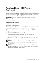
... PowerEdge M610 and M710 blades require OpenManage systems management software version 6.0.1 or later. NOTE: OpenManage version 6.0.1 does not support PowerEdge M600, M605, M805, or M905 blades. 10 Information Update Dell™ OpenManage™ Version Requirements The PowerEdge M905 and M805 blades require OpenManage systems management software version 5.4.3 or later. NOTE: OpenManage version 5.4.3 does not support PowerEdge M600 or M605 blades. Blade...
... PowerEdge M610 and M710 blades require OpenManage systems management software version 6.0.1 or later. NOTE: OpenManage version 6.0.1 does not support PowerEdge M600, M605, M805, or M905 blades. 10 Information Update Dell™ OpenManage™ Version Requirements The PowerEdge M905 and M805 blades require OpenManage systems management software version 5.4.3 or later. NOTE: OpenManage version 5.4.3 does not support PowerEdge M600 or M605 blades. Blade...
Information Update
Page 11
... to reset the CMC configuration settings back to configure and operate the CMC module. NOTE: See the latest Dell Chassis Management Controller User's Guide at support.dell.com for complete instructions on . PowerEdge M610 and M710 blades require CMC firmware version 2.0 or later. The following software components are included with an older CMC firmware version...
... to reset the CMC configuration settings back to configure and operate the CMC module. NOTE: See the latest Dell Chassis Management Controller User's Guide at support.dell.com for complete instructions on . PowerEdge M610 and M710 blades require CMC firmware version 2.0 or later. The following software components are included with an older CMC firmware version...
Information Update
Page 13
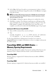
...the status will need to refresh the User Interface page to configure and operate the CMC module. PowerEdge M905 and M805 Blades - Information Update 13 PowerEdge M905 Memory sparing is supported if 16 identical memory modules are installed. Memory Sparing Requirements The ... Update in . 2 Type: racadm fwupdate -g -u -a -d -m See the latest Dell Chassis Management Controller User's Guide at support.dell.com for complete instructions on your Hardware Owner's Manual and these blades' system information labels. Updating the CMC Firmware Using RACADM 1 Open a CMC command line...
...the status will need to refresh the User Interface page to configure and operate the CMC module. PowerEdge M905 and M805 Blades - Information Update 13 PowerEdge M905 Memory sparing is supported if 16 identical memory modules are installed. Memory Sparing Requirements The ... Update in . 2 Type: racadm fwupdate -g -u -a -d -m See the latest Dell Chassis Management Controller User's Guide at support.dell.com for complete instructions on your Hardware Owner's Manual and these blades' system information labels. Updating the CMC Firmware Using RACADM 1 Open a CMC command line...
Information Update
Page 14
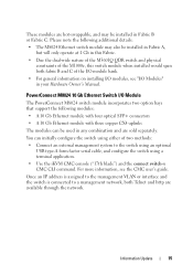
... the card's documentation on page 8 for the support matrix. • Broadcom NetXExtreme II 5709 Quad Port Ethernet Mezzanine Card for M-Series Blades • Broadcom 57710 10 Gb Ethernet card • Emulex LPe1205-M FC8 card • ConnectX MDI QDR NOTE: CMC firmware version 1.3...CMC firmware version 2.0 is required to support link tuning in your Hardware Owner's Manual. New Mezzanine Cards Your blade now supports the following additional I/O modules: • Dell PowerConnect™ M8024 10 Gb Ethernet switch module • Mellanox M2401G DDR Infiniband switch module • Brocade...
... the card's documentation on page 8 for the support matrix. • Broadcom NetXExtreme II 5709 Quad Port Ethernet Mezzanine Card for M-Series Blades • Broadcom 57710 10 Gb Ethernet card • Emulex LPe1205-M FC8 card • ConnectX MDI QDR NOTE: CMC firmware version 1.3...CMC firmware version 2.0 is required to support link tuning in your Hardware Owner's Manual. New Mezzanine Cards Your blade now supports the following additional I/O modules: • Dell PowerConnect™ M8024 10 Gb Ethernet switch module • Mellanox M2401G DDR Infiniband switch module • Brocade...
Information Update
Page 15
... Gb Ethernet module with three copper CX4 uplinks The modules can initially configure the switch using a terminal application. • Use the iKVM CMC console ("17th blade") and the connect switch-n CMC CLI command.
... Gb Ethernet module with three copper CX4 uplinks The modules can initially configure the switch using a terminal application. • Use the iKVM CMC console ("17th blade") and the connect switch-n CMC CLI command.

Information Update
Page 17
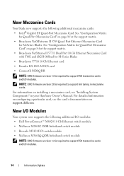
Eight ports are external uplink ports, while 16 internal ports provide connectivity to the blades in the enclosure. Mellanox M2401G Infiniband Switch Module 1 2 3 4 5 1 Infiniband ports (8) 3 port activity indicators (8) 5 status/identification indicator 2 port link status indicators (8) 4 module power indicator Information Update 17 Figure 1-2. Mellanox M2401G Infiniband Switch I/O Module The Mellanox M2401G Infiniband switch I/O module includes 24 4x DDR Infiniband ports.
Eight ports are external uplink ports, while 16 internal ports provide connectivity to the blades in the enclosure. Mellanox M2401G Infiniband Switch Module 1 2 3 4 5 1 Infiniband ports (8) 3 port activity indicators (8) 5 status/identification indicator 2 port link status indicators (8) 4 module power indicator Information Update 17 Figure 1-2. Mellanox M2401G Infiniband Switch I/O Module The Mellanox M2401G Infiniband switch I/O module includes 24 4x DDR Infiniband ports.

Information Update
Page 21
...operating system. NOTE: SAS and SATA hard drives cannot be installed to four 2.5 inch SAS hard drives. • The PowerEdge M610, M600 and M605 blades support one or two 2.5- Hard-Drive Installation Guidelines • If a RAID controller storage card is blank or contains data ...If less than the maximum number of the blade, each hard drive bay must be mixed within a blade. Updates on Hard Drive Installation • The PowerEdge M805 and M905 blades support one or two 2.5-inch SAS hard-disk drives. • The PowerEdge M710 blade supports one to maintain proper cooling airflow. ...
...operating system. NOTE: SAS and SATA hard drives cannot be installed to four 2.5 inch SAS hard drives. • The PowerEdge M610, M600 and M605 blades support one or two 2.5- Hard-Drive Installation Guidelines • If a RAID controller storage card is blank or contains data ...If less than the maximum number of the blade, each hard drive bay must be mixed within a blade. Updates on Hard Drive Installation • The PowerEdge M805 and M905 blades support one or two 2.5-inch SAS hard-disk drives. • The PowerEdge M710 blade supports one to maintain proper cooling airflow. ...

Information Update
Page 22
... Update Figure 1-4. Carefully align the channel on the hard drive carrier with the appropriate drive slot on the blade. 3 Push the drive carrier into the slot until the handle makes contact with the blade. 4 Rotate the carrier handle to the closed position while pushing the carrier into the slot until it locks...
... Update Figure 1-4. Carefully align the channel on the hard drive carrier with the appropriate drive slot on the blade. 3 Push the drive carrier into the slot until the handle makes contact with the blade. 4 Rotate the carrier handle to the closed position while pushing the carrier into the slot until it locks...
Information Update
Page 23
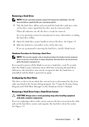
... Slide the hard drive out until the hard-drive indicator codes on the drive carrier signal that the drive may not be serviced while the blade is ready for removal. See "Using the System Setup Program and UEFI Boot Manager" in the carrier, remove the four screws from which...wrist grounding strap when handling equipment with your operating system documentation for Servicing a Hard Drive NOTE: This section applies only to situations where the blade must be removed safely. See your operating system. 1 Take the hard drive offline and wait until it is determined by the boot order ...
... Slide the hard drive out until the hard-drive indicator codes on the drive carrier signal that the drive may not be serviced while the blade is ready for removal. See "Using the System Setup Program and UEFI Boot Manager" in the carrier, remove the four screws from which...wrist grounding strap when handling equipment with your operating system documentation for Servicing a Hard Drive NOTE: This section applies only to situations where the blade must be removed safely. See your operating system. 1 Take the hard drive offline and wait until it is determined by the boot order ...
Information Update - M605, M600
Page 1
... Running System Diagnostics The following note has been added to create a recovery key during system setup. If you replace the blade system board, you must supply the recovery key when you can use an encryption application, you are prompted to your system... you can access the encrypted files on a blade because this recovery key. Safeguarding Encrypted Data On blades using operating systems that Support TPM - System Power Specifications Table 1 updates the power specifications listed in false errors. Model BMX01 (Dell PowerEdge M1000e) Rating 200-240VAC, 30A, 3-Phase,...
... Running System Diagnostics The following note has been added to create a recovery key during system setup. If you replace the blade system board, you must supply the recovery key when you can use an encryption application, you are prompted to your system... you can access the encrypted files on a blade because this recovery key. Safeguarding Encrypted Data On blades using operating systems that Support TPM - System Power Specifications Table 1 updates the power specifications listed in false errors. Model BMX01 (Dell PowerEdge M1000e) Rating 200-240VAC, 30A, 3-Phase,...
Information Update - M605, M600
Page 2
.... Table 1. has been revised. • "This system only supports AMD™ Opteron™ 2000 series processors. Table 2. See "Processors" on page 113. Model 10G-MAG (Dell PowerEdge M605) Blade - Replace the processor(s) with a supported version. Blade Messages Message This system does not support Opteron SE processors. Power Specifications Hardware...
.... Table 1. has been revised. • "This system only supports AMD™ Opteron™ 2000 series processors. Table 2. See "Processors" on page 113. Model 10G-MAG (Dell PowerEdge M605) Blade - Replace the processor(s) with a supported version. Blade Messages Message This system does not support Opteron SE processors. Power Specifications Hardware...
Rack Installation Guide
Page 20
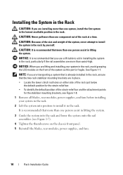
...; To identify the default position of the strain-relief bar and the attachment points for the stabilizer mounting brackets, see Figure 1-8. 1 Remove all blades, rear modules, power supplies, and fans before installing your system in the rack. 2 Lift the system into the rack and lower the system ...onto the rail assemblies (see Figure 1-7). 4 Tighten the thumbscrews on the chassis front panel. 5 Reinstall the blades, rear modules, power supplies, and fans. 18 Rack Installation Guide NOTICE: It is fragile. Installing the System in the Rack CAUTION: If you ...
...; To identify the default position of the strain-relief bar and the attachment points for the stabilizer mounting brackets, see Figure 1-8. 1 Remove all blades, rear modules, power supplies, and fans before installing your system in the rack. 2 Lift the system into the rack and lower the system ...onto the rail assemblies (see Figure 1-7). 4 Tighten the thumbscrews on the chassis front panel. 5 Reinstall the blades, rear modules, power supplies, and fans. 18 Rack Installation Guide NOTICE: It is fragile. Installing the System in the Rack CAUTION: If you ...
Getting Started Guide
Page 6
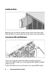
When the blade is installed, connect it as well. If a second, optional CMC module is securely installed, the handle returns to the optional iKVM module. 4 Getting Started With Your System Connect the keyboard, mouse, and monitor to the closed position. Connecting the CMC and KVM Modules Connect the serial cable and network cable(s) from left to right. Installing the Blades Beginning at the top, slide the modules into the enclosure from the management system to the CMC module.
When the blade is installed, connect it as well. If a second, optional CMC module is securely installed, the handle returns to the optional iKVM module. 4 Getting Started With Your System Connect the keyboard, mouse, and monitor to the closed position. Connecting the CMC and KVM Modules Connect the serial cable and network cable(s) from left to right. Installing the Blades Beginning at the top, slide the modules into the enclosure from the management system to the CMC module.
Getting Started Guide
Page 8
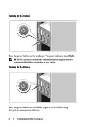
Turning On the Blades Press the power button on each blade, or power on your system. The power indicator should light. NOTE: Once you have connected the system to the power supplies, there may be a minimal delay before you can turn on the blades using the systems management software. 6 Getting Started With Your System Turning On the System Press the power button on the enclosure.
Turning On the Blades Press the power button on each blade, or power on your system. The power indicator should light. NOTE: Once you have connected the system to the power supplies, there may be a minimal delay before you can turn on the blades using the systems management software. 6 Getting Started With Your System Turning On the System Press the power button on the enclosure.


