Information Update
Page 4
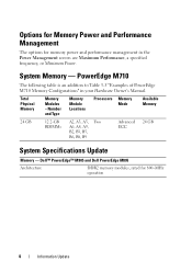
..., B9 Advanced 24 GB ECC System Specifications Update Memory - Dell™ PowerEdge™ M905 and Dell PowerEdge M805 Architecture DDR2 memory modules, rated for memory power and performance management in your Hardware Owner's Manual. PowerEdge M710 The following table is an addition to Table 3-5 "Examples of PowerEdge M710 Memory Configurations" in the Power Management screen are Maximum...
..., B9 Advanced 24 GB ECC System Specifications Update Memory - Dell™ PowerEdge™ M905 and Dell PowerEdge M805 Architecture DDR2 memory modules, rated for memory power and performance management in your Hardware Owner's Manual. PowerEdge M710 The following table is an addition to Table 3-5 "Examples of PowerEdge M710 Memory Configurations" in the Power Management screen are Maximum...
Information Update
Page 5
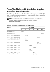
... (n+16) Port (n+16) Port n Port n Port (n+16) Port (n+16) Information Update 5 NOTE: For a detailed mapping of each PowerEdge system, see the document Quadport Capable Hardware For the M1000e Modular Chassis on support.dell.com/manuals. I/O Module Port Assignments-Half-Height Blades Blade n A1 Integrated LOM1 Port n Integrated LOM2 Mezz_FAB_B_Blade n_Port1 Mezz_FAB_B_Blade n_Port2 Mezz_FAB_B_Blade...
... (n+16) Port (n+16) Port n Port n Port (n+16) Port (n+16) Information Update 5 NOTE: For a detailed mapping of each PowerEdge system, see the document Quadport Capable Hardware For the M1000e Modular Chassis on support.dell.com/manuals. I/O Module Port Assignments-Half-Height Blades Blade n A1 Integrated LOM1 Port n Integrated LOM2 Mezz_FAB_B_Blade n_Port1 Mezz_FAB_B_Blade n_Port2 Mezz_FAB_B_Blade...
Information Update
Page 6
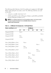
... of blade n and LOM3 and LOM4 are the LOM ports of blade (n+8) NOTE: For a detailed mapping of each PowerEdge system, see the document Quadport Capable Hardware For the M1000e Modular Chassis on support.dell.com/manuals. Table 1-2. The following table illustrates the I /O Module A1 B1 C1 C2 B2 A2 Integrated LOM1 Port n Integrated...
... of blade n and LOM3 and LOM4 are the LOM ports of blade (n+8) NOTE: For a detailed mapping of each PowerEdge system, see the document Quadport Capable Hardware For the M1000e Modular Chassis on support.dell.com/manuals. Table 1-2. The following table illustrates the I /O Module A1 B1 C1 C2 B2 A2 Integrated LOM1 Port n Integrated...
Information Update
Page 9
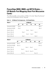
... I /O Module Port Mapping (Dual-Port Mezzanine Cards) The following tables correct portions of Table 1-12 in the "About Your System" section of your Hardware Owner's Manual. PowerEdge M905, M805, and M710 Blades - Table 1-4. I /O Module A1 B1 C1 C2 B2 A2 Port 4 Port 4 Port 12 Port 12 Port 4 Port 4 Port 4 Port 4 Port 12...
... I /O Module Port Mapping (Dual-Port Mezzanine Cards) The following tables correct portions of Table 1-12 in the "About Your System" section of your Hardware Owner's Manual. PowerEdge M905, M805, and M710 Blades - Table 1-4. I /O Module A1 B1 C1 C2 B2 A2 Port 4 Port 4 Port 12 Port 12 Port 4 Port 4 Port 4 Port 4 Port 12...
Information Update
Page 13
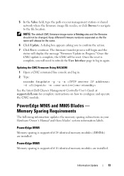
...Type: racadm fwupdate -g -u -a -d -m See the latest Dell Chassis Management Controller User's Guide at support.dell.com for complete instructions on your Hardware Owner's Manual and these blades' system information labels. PowerEdge M905 and M805 Blades - PowerEdge M905 Memory sparing is complete, you to confirm the action. ...dialog box appears asking you will be changed. Once the CMC update is supported if 16 identical memory modules are installed. PowerEdge M805 Memory sparing is complete, the CMC will need to refresh the User Interface page to configure and operate the CMC ...
...Type: racadm fwupdate -g -u -a -d -m See the latest Dell Chassis Management Controller User's Guide at support.dell.com for complete instructions on your Hardware Owner's Manual and these blades' system information labels. PowerEdge M905 and M805 Blades - PowerEdge M905 Memory sparing is complete, you to confirm the action. ...dialog box appears asking you will be changed. Once the CMC update is supported if 16 identical memory modules are installed. PowerEdge M805 Memory sparing is complete, the CMC will need to refresh the User Interface page to configure and operate the CMC ...
Information Update
Page 14
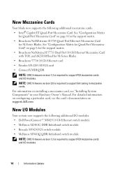
...System Components" in mezzanine cards. New Mezzanine Cards Your blade now supports the following additional I/O modules: • Dell PowerConnect™ M8024 10 Gb Ethernet switch module • Mellanox M2401G DDR Infiniband switch module • Brocade M5424 ... additional mezzanine cards: • Intel® Gigabit ET Quad-Port Mezzanine Card. For detailed information on support.dell.com. See "Configuration Matrix for Quad-Port Mezzanine Card" on page 8 for the support matrix. •...1.3 is required to support link tuning in your Hardware Owner's Manual. New I /O modules.
...System Components" in mezzanine cards. New Mezzanine Cards Your blade now supports the following additional I/O modules: • Dell PowerConnect™ M8024 10 Gb Ethernet switch module • Mellanox M2401G DDR Infiniband switch module • Brocade M5424 ... additional mezzanine cards: • Intel® Gigabit ET Quad-Port Mezzanine Card. For detailed information on support.dell.com. See "Configuration Matrix for Quad-Port Mezzanine Card" on page 8 for the support matrix. •...1.3 is required to support link tuning in your Hardware Owner's Manual. New I /O modules.
Information Update
Page 15
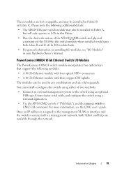
... the M1000e, this switch module when installed would span both Telnet and http are sold separately. For more information, see "I/O Modules" in your Hardware Owner's Manual. Please note the following modules: • A 10 Gb Ethernet module with four optical SFP+ connectors • A 10 Gb Ethernet module with three copper CX4 uplinks...
... the M1000e, this switch module when installed would span both Telnet and http are sold separately. For more information, see "I/O Modules" in your Hardware Owner's Manual. Please note the following modules: • A 10 Gb Ethernet module with four optical SFP+ connectors • A 10 Gb Ethernet module with three copper CX4 uplinks...
Information Update
Page 22
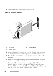
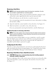
... 2 Insert the hard-drive carrier into place. If the drive carrier LED does not light, see "Troubleshooting SAS and SATA Drives" in your Hardware Owner's Manual. 22 Information Update Figure 1-4. The status LED indicator displays a steady green light if the drive is installed correctly. 1 Open the hard-drive carrier handle.
... 2 Insert the hard-drive carrier into place. If the drive carrier LED does not light, see "Troubleshooting SAS and SATA Drives" in your Hardware Owner's Manual. 22 Information Update Figure 1-4. The status LED indicator displays a steady green light if the drive is installed correctly. 1 Open the hard-drive carrier handle.
Information Update
Page 23
... the carrier, remove the four screws from the slide rails on . See "Using the System Setup Program and UEFI Boot Manager" in the Hardware Owner's Manual.
... the carrier, remove the four screws from the slide rails on . See "Using the System Setup Program and UEFI Boot Manager" in the Hardware Owner's Manual.

Information Update - M605, M600
Page 1
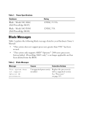
... key during system setup. If you replace the blade system board, you must supply the recovery key when you restart your hard drive(s). Model BMX01 (Dell PowerEdge M1000e) Rating 200-240VAC, 30A, 3-Phase, 50/60Hz 200-240VAC, 45A, Single Phase, 50/60Hz 200-240VAC, 30A, 50/60Hz November 2007 System Power Specifications... recovery key. Running System Diagnostics The following note has been added to store this could interfere with the test and result in your Hardware Owner's Manual. Be sure to your Getting Started Guide and Product Information Guide.
... key during system setup. If you replace the blade system board, you must supply the recovery key when you restart your hard drive(s). Model BMX01 (Dell PowerEdge M1000e) Rating 200-240VAC, 30A, 3-Phase, 50/60Hz 200-240VAC, 45A, Single Phase, 50/60Hz 200-240VAC, 30A, 50/60Hz November 2007 System Power Specifications... recovery key. Running System Diagnostics The following note has been added to store this could interfere with the test and result in your Hardware Owner's Manual. Be sure to your Getting Started Guide and Product Information Guide.
Information Update - M605, M600
Page 2
... system does not support Opteron SE processors. Model 10G-TOM (Dell PowerEdge M600) Rating 12VDC, 33.33A 12VDC, 35A Blade Messages Table 2 updates the following blade messages listed in your Hardware Owner's Manual: • "This system does not support processors greater than ...95W." Model 10G-MAG (Dell PowerEdge M605) Blade - Power Specifications Hardware Blade - System halted. (PowerEdge M605 only)" is no longer applicable and has been deleted ...
... system does not support Opteron SE processors. Model 10G-TOM (Dell PowerEdge M600) Rating 12VDC, 33.33A 12VDC, 35A Blade Messages Table 2 updates the following blade messages listed in your Hardware Owner's Manual: • "This system does not support processors greater than ...95W." Model 10G-MAG (Dell PowerEdge M605) Blade - Power Specifications Hardware Blade - System halted. (PowerEdge M605 only)" is no longer applicable and has been deleted ...
Information Update - Processor Installation
Page 3
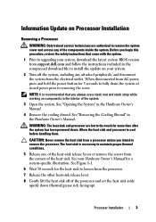
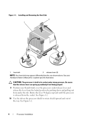
... trained service technicians are hot to loosen from the corners of the heat sink. See "Removing the Cooling Shroud" in the Hardware Owner's Manual. 4 Remove the cooling shroud. WARNING: The heat sink and processor are authorized to remove the system cover and access any attached peripherals, ...and disconnect the system from support.dell.com and follow the instructions included in the interior of the system. 3 Open the system. See your system. 2 Turn off of the...
... trained service technicians are hot to loosen from the corners of the heat sink. See "Removing the Cooling Shroud" in the Hardware Owner's Manual. 4 Remove the cooling shroud. WARNING: The heat sink and processor are authorized to remove the system cover and access any attached peripherals, ...and disconnect the system from support.dell.com and follow the instructions included in the interior of the system. 3 Open the system. See your system. 2 Turn off of the...
Information Update - Processor Installation
Page 4
... held in its socket under the tab. Be aware that the release lever can spring up suddenly if not firmly grasped. 9 Position your Hardware Owner's Manual for a system-specific illustration. See your thumb firmly over the processor socket-release lever and release the lever from the locked position by pushing down...
... held in its socket under the tab. Be aware that the release lever can spring up suddenly if not firmly grasped. 9 Position your Hardware Owner's Manual for a system-specific illustration. See your thumb firmly over the processor socket-release lever and release the lever from the locked position by pushing down...
Information Update - Processor Installation
Page 9
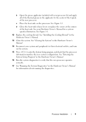
... and turn on the processor. See "Installing the Cooling Shroud" in the Hardware Owner's Manual for a systemspecific illustration. See "Closing the System" in the Hardware Owner's Manual. 14 Reconnect your system and peripherals to enter the System Setup program, and check that the... operates correctly. 17 See "Running the System Diagnostics" in the Hardware Owner's Manual. 13 Close the system. Processor Installation 9 b Open the grease applicator included with your Hardware Owner's Manual for information about running the diagnostics. d Close the heat-sink release levers or...
... and turn on the processor. See "Installing the Cooling Shroud" in the Hardware Owner's Manual for a systemspecific illustration. See "Closing the System" in the Hardware Owner's Manual. 14 Reconnect your system and peripherals to enter the System Setup program, and check that the... operates correctly. 17 See "Running the System Diagnostics" in the Hardware Owner's Manual. 13 Close the system. Processor Installation 9 b Open the grease applicator included with your Hardware Owner's Manual for information about running the diagnostics. d Close the heat-sink release levers or...

AMD Processor Update
Page 1
... to 5 MB. During system startup, the system BIOS checks the system board revision number and the HT capability of running at www.support.dell.com/manuals. If your system's HyperTransport mode to HT3 by default. Your system and/or processors may or may not be enabled or disabled using your... your system capability, you the best performance for your system's BIOS settings. For information on accessing BIOS settings, see your system's Hardware Owner's Manual on which setting gives you can then set the field to HT1 and read only. If the system is set to either HT1 or HT3...
... to 5 MB. During system startup, the system BIOS checks the system board revision number and the HT capability of running at www.support.dell.com/manuals. If your system's HyperTransport mode to HT3 by default. Your system and/or processors may or may not be enabled or disabled using your... your system capability, you the best performance for your system's BIOS settings. For information on accessing BIOS settings, see your system's Hardware Owner's Manual on which setting gives you can then set the field to HT1 and read only. If the system is set to either HT1 or HT3...
Dell 10 Gb Ethernet Pass Through-k for M1000e Software User’s Manual
Page 4
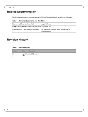
Revision History Revision 1.0 Date Description April 01st, Initial Release 2011 4 Rev 1.0 Related Documentation The documentation set accompanying the DEll Pass Through Module includes the following: Table 1 - Reference Documents and Web Sites Firmware and Firmware Update Tools support.dell.com Dell Pass Through Module Software User Manual support.dell.com Latest Supported Cables and Optical Modules See Supported Cables and Media Types on page 18 in this document Revision History Table 2 -
Revision History Revision 1.0 Date Description April 01st, Initial Release 2011 4 Rev 1.0 Related Documentation The documentation set accompanying the DEll Pass Through Module includes the following: Table 1 - Reference Documents and Web Sites Firmware and Firmware Update Tools support.dell.com Dell Pass Through Module Software User Manual support.dell.com Latest Supported Cables and Optical Modules See Supported Cables and Media Types on page 18 in this document Revision History Table 2 -

Dell 10 Gb Ethernet Pass Through-k for M1000e Software User’s Manual
Page 5
The term PTM is intended for users and system administrators responsible for installing and setting up the Dell 10Gb Ethernet Pass Through -k module for blade servers. Conventions The terms downlink (internal-from servers) and uplink (external-out to the... or installer. Caution: This symbol indicates the possibility of the Dell 10Gb Ethernet Pass Through -k 16 port module for blade servers. Intended Audience This manual is used throughout the document. Dell -10GbE PTM About this Manual Rev 1.0 This manual describes the installation and basic use of physical injury to indicate ...
The term PTM is intended for users and system administrators responsible for installing and setting up the Dell 10Gb Ethernet Pass Through -k module for blade servers. Conventions The terms downlink (internal-from servers) and uplink (external-out to the... or installer. Caution: This symbol indicates the possibility of the Dell 10Gb Ethernet Pass Through -k 16 port module for blade servers. Intended Audience This manual is used throughout the document. Dell -10GbE PTM About this Manual Rev 1.0 This manual describes the installation and basic use of physical injury to indicate ...

Dell 10 Gb Ethernet Pass Through-k for M1000e Software User’s Manual
Page 8
... PTM Slot A1 Slot B1 Slot C1 Slot C2 Slot B2 Slot A2 8 Your package should contain the following diagram: Figure 3: Dell Chassis Slots for Blade Servers • This Users Manual The PTM is no visible damage that may be plugged into fabric slots A1, A2, B1, B2, C1, and C2. Rev...
... PTM Slot A1 Slot B1 Slot C1 Slot C2 Slot B2 Slot A2 8 Your package should contain the following diagram: Figure 3: Dell Chassis Slots for Blade Servers • This Users Manual The PTM is no visible damage that may be plugged into fabric slots A1, A2, B1, B2, C1, and C2. Rev...
Dell 10 Gb Ethernet Pass Through-k for M1000e Software User’s Manual
Page 19
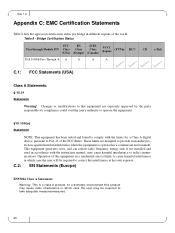
... to operate the equipment. §15.105(a) Statement NOTE: This equipment has been tested and found to comply with the instruction manual, may cause radio interference in which case the user will be required to take adequate measuresmeasures. 20 C.2: EN Statements (Europe) ...Operation of the world. Bridge Certification Status Pass through Module P/N FCC Class (USA) EN Class (Europe) ICES Class (Canada) VCCI (Japan) cTUVus KCC Dell 10GbE Pass Through -k A A A A CB c-Tick C.1: FCC Statements (USA) Class A Statements: § 15.21 Statement Warning! Changes or modifications ...
... to operate the equipment. §15.105(a) Statement NOTE: This equipment has been tested and found to comply with the instruction manual, may cause radio interference in which case the user will be required to take adequate measuresmeasures. 20 C.2: EN Statements (Europe) ...Operation of the world. Bridge Certification Status Pass through Module P/N FCC Class (USA) EN Class (Europe) ICES Class (Canada) VCCI (Japan) cTUVus KCC Dell 10GbE Pass Through -k A A A A CB c-Tick C.1: FCC Statements (USA) Class A Statements: § 15.21 Statement Warning! Changes or modifications ...

Dell 10 Gb Ethernet Pass Through-k for M1000e Software User’s Manual (For System Administrators)
Page 1
Dell 10Gb Ethernet Pass Through -k for M1000e Software User's Manual Rev 1.00 This document is intended for administrators.
Dell 10Gb Ethernet Pass Through -k for M1000e Software User's Manual Rev 1.00 This document is intended for administrators.

