
Information Update - Power Infrastructure Sizing
Page 1
.... Combined use of the hardware. Using system power capping at 1000W and the characterization results in a significantly different power consumption requirement than 50 percent. Systems characterized while using the power capping features enabled from Dell may result in 500W of Power Distribution Units (PDUs), Uninterruptible Power Supplies (UPSs), and other power infrastructure distribution equipment. If a system is rated...
.... Combined use of the hardware. Using system power capping at 1000W and the characterization results in a significantly different power consumption requirement than 50 percent. Systems characterized while using the power capping features enabled from Dell may result in 500W of Power Distribution Units (PDUs), Uninterruptible Power Supplies (UPSs), and other power infrastructure distribution equipment. If a system is rated...
Dell PowerEdge M1000e Configuration Guide
Page 13
...CMC, the iDRAC in each component in the enclosure. An active module is designated by a green rectangle. About Your System 13 A module that is powered off or booting is indicated by a gray rectangle. If a module is indicated by an amber rectangle. - If a module has errors, it is...the module and any errors present. • In the Enclosure Status dialog box, you can view the enclosure status, any error conditions, and power consumption statistics. • The Network Summary screen lists the IP addresses for Module Status, Enclosure Status, and Network Summary. • In the ...
...CMC, the iDRAC in each component in the enclosure. An active module is designated by a green rectangle. About Your System 13 A module that is powered off or booting is indicated by a gray rectangle. If a module is indicated by an amber rectangle. - If a module has errors, it is...the module and any errors present. • In the Enclosure Status dialog box, you can view the enclosure status, any error conditions, and power consumption statistics. • The Network Summary screen lists the IP addresses for Module Status, Enclosure Status, and Network Summary. • In the ...
Dell PowerEdge M1000e Configuration Guide
Page 35
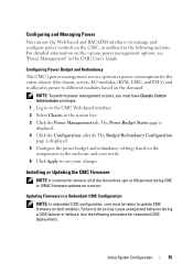
...the CMC User's Guide. The Power Budget Status page is displayed. 5 Configure the power budget and redundancy settings based on a server. Initial System Configuration 35 Configuring Power Budget and Redundancy The CMC's power management service optimizes power consumption for some or all of the... fan units to save your changes. Updating Firmware in the system tree. 3 Click the Power Management tab. Installing or Updating the...
...the CMC User's Guide. The Power Budget Status page is displayed. 5 Configure the power budget and redundancy settings based on a server. Initial System Configuration 35 Configuring Power Budget and Redundancy The CMC's power management service optimizes power consumption for some or all of the... fan units to save your changes. Updating Firmware in the system tree. 3 Click the Power Management tab. Installing or Updating the...

Hardware Owner's Manual
Page 19
... the health and status of the modules in the system. • Real time power consumption statistics, including high and low values, and average power consumption. • Ambient temperature values. • AC power information • Critical failure alerts and warnings. LCD Module Screen Navigation Keys Keys ... Status information screens for the modules installed in the back of the enclosure, including the IO modules, fans, CMC, iKVM, and power supplies. • A network summary screen listing the IP addresses of all components in the enclosure. About Your System 19 LCD Module...
... the health and status of the modules in the system. • Real time power consumption statistics, including high and low values, and average power consumption. • Ambient temperature values. • AC power information • Critical failure alerts and warnings. LCD Module Screen Navigation Keys Keys ... Status information screens for the modules installed in the back of the enclosure, including the IO modules, fans, CMC, iKVM, and power supplies. • A network summary screen listing the IP addresses of all components in the enclosure. About Your System 19 LCD Module...

Hardware Owner's Manual
Page 21
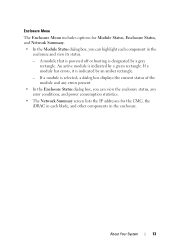
...is indicated by a gray rectangle. An active blade is selected, a dialog box displays the current status of the blade and any error conditions, and power consumption statistics. • The Network Summary screen lists the IP addresses for the LCD menu screens using the arrow keys, and view its status. - A... the Server Menu dialog box, you can highlight each component in the enclosure and view its status. • A blade that is powered off or booting is indicated by an amber rectangle. - About Your System 21 An active module is designated by a green rectangle.
...is indicated by a gray rectangle. An active blade is selected, a dialog box displays the current status of the blade and any error conditions, and power consumption statistics. • The Network Summary screen lists the IP addresses for the LCD menu screens using the arrow keys, and view its status. - A... the Server Menu dialog box, you can highlight each component in the enclosure and view its status. • A blade that is powered off or booting is indicated by an amber rectangle. - About Your System 21 An active module is designated by a green rectangle.
Hardware Owner's Manual
Page 45
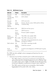
... (115200 baud, No parity, 8, 1) The CMC provides multiple systems management functions for your modular server: • Enclosure-level real-time automatic power and thermal management. - The CMC reports real-time power consumption, which includes logging high and low points with a time stamp. Fault indicator Off The CMC is not active. LAN is the...
... (115200 baud, No parity, 8, 1) The CMC provides multiple systems management functions for your modular server: • Enclosure-level real-time automatic power and thermal management. - The CMC reports real-time power consumption, which includes logging high and low points with a time stamp. Fault indicator Off The CMC is not active. LAN is the...

Hardware Owner's Manual
Page 107
... Blade Messages (continued) Message Causes Corrective Actions Current Overlimit detected in the dedicated slot. NOTE: Applicable to M610x only. card. See controller slot. not have power consumption more information, see "Expansion Card Installation Guidelines" on page 218. NOTE: Applicable to M610x only. See "Installing an Expansion Card" on page 217. For more...
... Blade Messages (continued) Message Causes Corrective Actions Current Overlimit detected in the dedicated slot. NOTE: Applicable to M610x only. card. See controller slot. not have power consumption more information, see "Expansion Card Installation Guidelines" on page 218. NOTE: Applicable to M610x only. See "Installing an Expansion Card" on page 217. For more...
Hardware Owner's Manual
Page 217
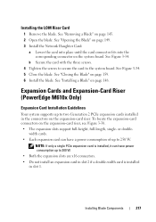
... To locate the expansion-card connectors on page 145. 2 Open the blade. or double- width cards. • Each expansion card can have a power consumption of up to 300 W. • Both the expansion slots are x16 connectors. • Do not install an expansion card in slot 2 if a ...See "Closing the Blade" on the system board. See "Installing a Blade" on the expansion-card riser. Expansion Cards and Expansion-Card Riser (PowerEdge M610x Only) Expansion Card Installation Guidelines Your system supports up to 250 W. b Secure the card with the three screws. 4 Tighten the screws to...
... To locate the expansion-card connectors on page 145. 2 Open the blade. or double- width cards. • Each expansion card can have a power consumption of up to 300 W. • Both the expansion slots are x16 connectors. • Do not install an expansion card in slot 2 if a ...See "Closing the Blade" on the system board. See "Installing a Blade" on the expansion-card riser. Expansion Cards and Expansion-Card Riser (PowerEdge M610x Only) Expansion Card Installation Guidelines Your system supports up to 250 W. b Secure the card with the three screws. 4 Tighten the screws to...
Hardware Owner's Manual
Page 265
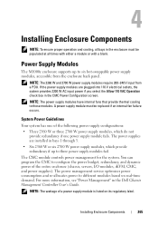
... the Allow 110 VAC Operation check box in the CMC Power Configuration screen. The power management service optimizes power consumption and re-allocates power to six hot-swappable power supply modules, accessible from a PDU. If the power supply modules are installed in the Dell Chassis Management Controller User's Guide. A power supply module must be replaced if an internal fan...
... the Allow 110 VAC Operation check box in the CMC Power Configuration screen. The power management service optimizes power consumption and re-allocates power to six hot-swappable power supply modules, accessible from a PDU. If the power supply modules are installed in the Dell Chassis Management Controller User's Guide. A power supply module must be replaced if an internal fan...

Dell M8428-k Hardware Reference Manual
Page 41
TABLE 8 Electrical specifications and requirements Dimension Measurements DC input Power consumption 12 V and 3.3 V from chassis About 60 W normally and 70 W maximum measured Architectural specification The switch module meets the specifications... SNMP, Web Tools, Enhanced Group Management, Fabric Watch, Advanced Zoning, ISL Trunking, Advanced Performance Monitoring, Data Center Fabric Manager (DCFM) Dell M8428-k Hardware Reference Manual 29 53-1001980-01 TABLE 9 Feature Architecture Description Scalability Certified maximum Performance -FC ports Performance -CEE ports Fabric latency...
TABLE 8 Electrical specifications and requirements Dimension Measurements DC input Power consumption 12 V and 3.3 V from chassis About 60 W normally and 70 W maximum measured Architectural specification The switch module meets the specifications... SNMP, Web Tools, Enhanced Group Management, Fabric Watch, Advanced Zoning, ISL Trunking, Advanced Performance Monitoring, Data Center Fabric Manager (DCFM) Dell M8428-k Hardware Reference Manual 29 53-1001980-01 TABLE 9 Feature Architecture Description Scalability Certified maximum Performance -FC ports Performance -CEE ports Fabric latency...
Fabric OS Command Reference Manual Supporting Fabric
Page 142
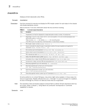
... Num: xxxxxxxxxxxxxxxxxxxx 13 Externally supplied serial number (up to 20 characters): Serial Num:xxxxxxxxxxxxxxxxxxxx 14 Externally supplied revision number (up to calculate the object's power consumption: positive for power supplies and negative for consumers. TABLE 5 Command output descriptions Line Description 1 If applicable, the first line displays the chassis backplane version number, in the...
... Num: xxxxxxxxxxxxxxxxxxxx 13 Externally supplied serial number (up to 20 characters): Serial Num:xxxxxxxxxxxxxxxxxxxx 14 Externally supplied revision number (up to calculate the object's power consumption: positive for power supplies and negative for consumers. TABLE 5 Command output descriptions Line Description 1 If applicable, the first line displays the chassis backplane version number, in the...
Fabric OS Command Reference Manual Supporting Fabric
Page 910
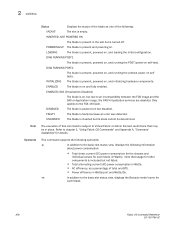
... or Admin Domain restrictions that usage for other components is included but not listed. • Total alternating current (AC) power consumption in Watts. • AC efficiency, as one of total and BTU. • Power efficiency in the slot but disabled. LOADING The blade is on , and loading the initial configuration. ENABLED The blade...
... or Admin Domain restrictions that usage for other components is included but not listed. • Total alternating current (AC) power consumption in Watts. • AC efficiency, as one of total and BTU. • Power efficiency in the slot but disabled. LOADING The blade is on , and loading the initial configuration. ENABLED The blade...
Fabric OS Command Reference Manual Supporting Fabric
Page 911
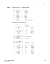
...BLADE 33 LOADING 11 SW BLADE 55 DIAG RUNNING POST1 12 SW BLADE 51 INSERTED, NOT POWERED ON 1 To display power consumption information: switch:user> slotshow -p Slot Blade Type ID DC Power Status Consumption 1 SW BLADE 77 130 ENABLED 2 SW BLADE 51 115 ENABLED 3 CORE BLADE 46... 60 ENABLED 7 AP BLADE 74 250 ENABLED 8 AP BLADE 74 250 FAULTY (21) Total DC Power Consumption: 1199 watts Total AC Power Consumption: 1332 watts AC @ 90% efficiency (4546 BTU) Power Efficiency: 1.04 watts per port, 0.26 watts per Gb To display Brocade model names for each ...
...BLADE 33 LOADING 11 SW BLADE 55 DIAG RUNNING POST1 12 SW BLADE 51 INSERTED, NOT POWERED ON 1 To display power consumption information: switch:user> slotshow -p Slot Blade Type ID DC Power Status Consumption 1 SW BLADE 77 130 ENABLED 2 SW BLADE 51 115 ENABLED 3 CORE BLADE 46... 60 ENABLED 7 AP BLADE 74 250 ENABLED 8 AP BLADE 74 250 FAULTY (21) Total DC Power Consumption: 1199 watts Total AC Power Consumption: 1332 watts AC @ 90% efficiency (4546 BTU) Power Efficiency: 1.04 watts per port, 0.26 watts per Gb To display Brocade model names for each ...

