Hardware Owner's Manual
Page 14
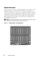
... a system, a blade is inserted into an enclosure (chassis) that supports power supplies, fan modules, a Chassis Management Controller (CMC) module, and at all bays in the PowerEdge M1000e enclosure. Figure 1-1.
... a system, a blade is inserted into an enclosure (chassis) that supports power supplies, fan modules, a Chassis Management Controller (CMC) module, and at all bays in the PowerEdge M1000e enclosure. Figure 1-1.
Hardware Owner's Manual
Page 20
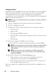
... your network. 20 About Your System To set a static IP address for the iDRAC using a management station and CLI commands. (For more information, see the PowerEdge M1000e Configuration Guide or CMC documentation.) NOTE: After you must toggle the CMC setting from DHCP to manually configure the iDRAC settings. NOTE: You cannot set...
... your network. 20 About Your System To set a static IP address for the iDRAC using a management station and CLI commands. (For more information, see the PowerEdge M1000e Configuration Guide or CMC documentation.) NOTE: After you must toggle the CMC setting from DHCP to manually configure the iDRAC settings. NOTE: You cannot set...

Hardware Owner's Manual
Page 29
... the System Setup program.(If the power button option is pressed. • Press and hold the button to the blade, the blade is in the M1000e enclosure. Normal operating state. Green on page 148. Turns blade power off and on .
... the System Setup program.(If the power button option is pressed. • Press and hold the button to the blade, the blade is in the M1000e enclosure. Normal operating state. Green on page 148. Turns blade power off and on .

Hardware Owner's Manual
Page 46
.... Power redundancy and power ceiling settings - First boot device on actual ambient and internal temperature measurements. - The M1000e enclosure's network and security settings - See the latest Dell Chassis Management Controller User's Guide at support.dell.com for complete instructions on the blades to set up of the following: - The CMC monitors and automatically...
.... Power redundancy and power ceiling settings - First boot device on actual ambient and internal temperature measurements. - The M1000e enclosure's network and security settings - See the latest Dell Chassis Management Controller User's Guide at support.dell.com for complete instructions on the blades to set up of the following: - The CMC monitors and automatically...
Hardware Owner's Manual
Page 48
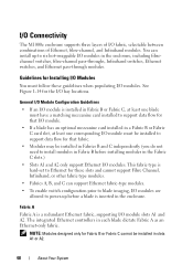
... a Fabric B or Fabric C card slot, at least one corresponding I /O modules. NOTE: Modules designed only for the I /O fabric, selectable between combinations of I /O bay locations. I/O Connectivity The M1000e enclosure supports three layers of Ethernet, fibre-channel, and Infiniband modules. The integrated Ethernet controllers in slots A1 or A2. 48 About Your System See...
... a Fabric B or Fabric C card slot, at least one corresponding I /O modules. NOTE: Modules designed only for the I /O fabric, selectable between combinations of I /O bay locations. I/O Connectivity The M1000e enclosure supports three layers of Ethernet, fibre-channel, and Infiniband modules. The integrated Ethernet controllers in slots A1 or A2. 48 About Your System See...

Hardware Owner's Manual
Page 60
... Port n Port (n+16) Port n Port n Port (n+16) Port (n+16) Port (n+8) Port (n+8) Port (n+24) 60 About Your System Table 1-15. NOTE: For a detailed mapping of each PowerEdge system, see the document Quadport Capable Hardware for full-height blades with quad-port mezzanine cards. Quad-Port Mezzanine Cards Table 1-15 illustrates the I/O module...
... Port n Port (n+16) Port n Port n Port (n+16) Port (n+16) Port (n+8) Port (n+8) Port (n+24) 60 About Your System Table 1-15. NOTE: For a detailed mapping of each PowerEdge system, see the document Quadport Capable Hardware for full-height blades with quad-port mezzanine cards. Quad-Port Mezzanine Cards Table 1-15 illustrates the I/O module...
Hardware Owner's Manual
Page 65
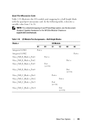
...) Port (n+16) Port n Port n Port (n+16) Port (n+16) About Your System 65 NOTE: For a detailed mapping of each PowerEdge system, see the document Quadport Capable Hardware For the M1000e Modular Chassis on support.dell.com/manuals. In the following table, n denotes a variable value from 1 to 16. I/O Module Port Assignments-Half-Height Blades Blade...
...) Port (n+16) Port n Port n Port (n+16) Port (n+16) About Your System 65 NOTE: For a detailed mapping of each PowerEdge system, see the document Quadport Capable Hardware For the M1000e Modular Chassis on support.dell.com/manuals. In the following table, n denotes a variable value from 1 to 16. I/O Module Port Assignments-Half-Height Blades Blade...

Hardware Owner's Manual
Page 146
Removing and Installing a Half-Height Blade 3 2 1 4 5 1 blade handle 2 release button 3 blade 4 guide rail on M1000e enclosure 5 guide rail on blade (or blade blank) 146 Installing Blade Components Figure 3-1.
Removing and Installing a Half-Height Blade 3 2 1 4 5 1 blade handle 2 release button 3 blade 4 guide rail on M1000e enclosure 5 guide rail on blade (or blade blank) 146 Installing Blade Components Figure 3-1.

Hardware Owner's Manual
Page 147
Removing and Installing a Full-Height Blade 3 2 1 4 5 1 blade handle 3 blade 5 guide rail on blade 2 release button 4 guide rail on M1000e enclosure Installing Blade Components 147 Figure 3-2.
Removing and Installing a Full-Height Blade 3 2 1 4 5 1 blade handle 3 blade 5 guide rail on blade 2 release button 4 guide rail on M1000e enclosure Installing Blade Components 147 Figure 3-2.

Hardware Owner's Manual
Page 148
... of the blank faceplate, and slide the blank out of the enclosure. 148 Installing Blade Components See "Installing a Blade Blank" on the floor of the M1000e enclosure. Removing a Blade Blank If you are removing a blade blank from one of the eight lower bays, press the blue latch at the upper edge...
... of the blank faceplate, and slide the blank out of the enclosure. 148 Installing Blade Components See "Installing a Blade Blank" on the floor of the M1000e enclosure. Removing a Blade Blank If you are removing a blade blank from one of the eight lower bays, press the blue latch at the upper edge...

Hardware Owner's Manual
Page 149
... blank in Figure 3-3 so that the cover-release latch faces up. 4 Lift the cover-release latch and slide the cover toward the back of the M1000e enclosure, and slide the blank into the enclosure until it stops. 5 Carefully lift the cover away from the enclosure. A full-height blade requires two connector...
... blank in Figure 3-3 so that the cover-release latch faces up. 4 Lift the cover-release latch and slide the cover toward the back of the M1000e enclosure, and slide the blank into the enclosure until it stops. 5 Carefully lift the cover away from the enclosure. A full-height blade requires two connector...
Hardware Owner's Manual
Page 265
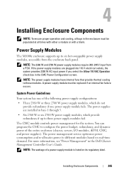
... power supply modules fail. Installing Enclosure Components 265 If the power supply modules are installed in the CMC Power Configuration screen. Power Supply Modules The M1000e enclosure supports up to different modules based on its regulatory label. You can program the CMC to configure the power budget, redundancy, and dynamic power... that provide thermal cooling to six hot-swappable power supply modules, accessible from a PDU. A power supply module must be populated at all bays in the Dell Chassis Management Controller User's Guide.
... power supply modules fail. Installing Enclosure Components 265 If the power supply modules are installed in the CMC Power Configuration screen. Power Supply Modules The M1000e enclosure supports up to different modules based on its regulatory label. You can program the CMC to configure the power budget, redundancy, and dynamic power... that provide thermal cooling to six hot-swappable power supply modules, accessible from a PDU. A power supply module must be populated at all bays in the Dell Chassis Management Controller User's Guide.
Hardware Owner's Manual
Page 266
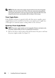
...: PDU inlet cords for this is the case, remove the wire guides by removing the attachment screw securing each guide. Power Supply Blanks If the M1000e enclosure is turned on. 1 Release the power cord retention clip and disconnect the power cord from the power supply module. If this system may be...
...: PDU inlet cords for this is the case, remove the wire guides by removing the attachment screw securing each guide. Power Supply Blanks If the M1000e enclosure is turned on. 1 Release the power cord retention clip and disconnect the power cord from the power supply module. If this system may be...

Hardware Owner's Manual
Page 269
Fan Modules The M1000e enclosure contains nine hot-swappable fan modules. See Figure 1-17. 2 Remove the fan module: a Press the fan-module release button. b Slide the fan module out ...
Fan Modules The M1000e enclosure contains nine hot-swappable fan modules. See Figure 1-17. 2 Remove the fan module: a Press the fan-module release button. b Slide the fan module out ...

Hardware Owner's Manual
Page 272
... and insert the contact-pin end of the card into the slot with the label on the passive module. 1 Remove the CMC module from the M1000e enclosure. See Figure 4-5. Installing an SD Card in the CMC Module 1 2 1 SD card 2 SD card connector 272 Installing Enclosure Components NOTE: Verify the write protection...
... and insert the contact-pin end of the card into the slot with the label on the passive module. 1 Remove the CMC module from the M1000e enclosure. See Figure 4-5. Installing an SD Card in the CMC Module 1 2 1 SD card 2 SD card connector 272 Installing Enclosure Components NOTE: Verify the write protection...

Hardware Owner's Manual
Page 276
... installation. See "I/O Module Mezzanine Cards" on using the cable enumerators to organize and manage the cables. 5 A matching fabric mezzanine card must be installed in the M1000e enclosure: a Lift the handle release latch and open the I/O module handle. See Figure 4-6. 3 Install the I/O module in one or more blades to turn off the...
... installation. See "I/O Module Mezzanine Cards" on using the cable enumerators to organize and manage the cables. 5 A matching fabric mezzanine card must be installed in the M1000e enclosure: a Lift the handle release latch and open the I/O module handle. See Figure 4-6. 3 Install the I/O module in one or more blades to turn off the...
Hardware Owner's Manual
Page 295
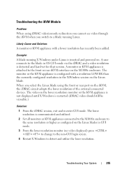
The lower resolution is communicated and utilized. 2 Set all monitors or KVM appliances connected to the M1000e enclosure to the same resolution or higher as configured on the Linux blades in GUI mode. 3 From the lower resolution monitor (no video displayed) press ... the iDRAC and a video resolution is detected and hard-set for that session. When you switch to the front or rear iKVM interface on the M1000e enclosure. Example: A blade running Linux. The monitor or the KVM appliance is attached to a blade running X Windows under Linux is restarted (iDRAC video should still...
The lower resolution is communicated and utilized. 2 Set all monitors or KVM appliances connected to the M1000e enclosure to the same resolution or higher as configured on the Linux blades in GUI mode. 3 From the lower resolution monitor (no video displayed) press ... the iDRAC and a video resolution is detected and hard-set for that session. When you switch to the front or rear iKVM interface on the M1000e enclosure. Example: A blade running Linux. The monitor or the KVM appliance is attached to a blade running X Windows under Linux is restarted (iDRAC video should still...

Dell M8428-k Hardware Reference Manual
Page 13
... internal CEE ports can operate at 10 Gbps. The Dell M8428-k ships with 8 external Converged Enhanced Ethernet (CEE) ports, 4 external Fibre Channel (FC) ports, and 16 internal CEE ports that installs in a Dell PowerEdge M1000e Blade Server Enclosure. This technology provides the ability to attach... more domains. The 16 internal ports connect to be done through Dell Chassis Management Controller (CMC), the browser based GUI, or the command...
... internal CEE ports can operate at 10 Gbps. The Dell M8428-k ships with 8 external Converged Enhanced Ethernet (CEE) ports, 4 external Fibre Channel (FC) ports, and 16 internal CEE ports that installs in a Dell PowerEdge M1000e Blade Server Enclosure. This technology provides the ability to attach... more domains. The 16 internal ports connect to be done through Dell Chassis Management Controller (CMC), the browser based GUI, or the command...

Dell M8428-k Hardware Reference Manual
Page 18
... the following optional software, which is activated with installation requirements in the Blade Server Enclosure Hardware Owner's Manual. 6 Dell M8428-k Hardware Reference Manual 53-1001980-01 NOTE The converged network switch is installed in NPIV or full fabric mode.... 25 provides details about removing transceivers from the converged network switch. Make sure to comply with the purchase of the Dell M1000e Blade Server Enclosure for easy identification. 1 ISL trunking groups Transceivers provide optical connections to the manufacturer's instructions when installing...
... the following optional software, which is activated with installation requirements in the Blade Server Enclosure Hardware Owner's Manual. 6 Dell M8428-k Hardware Reference Manual 53-1001980-01 NOTE The converged network switch is installed in NPIV or full fabric mode.... 25 provides details about removing transceivers from the converged network switch. Make sure to comply with the purchase of the Dell M1000e Blade Server Enclosure for easy identification. 1 ISL trunking groups Transceivers provide optical connections to the manufacturer's instructions when installing...
Information Update
Page 5
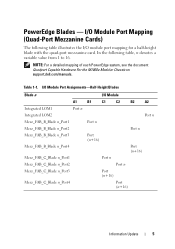
... Mezz_FAB_C_Blade n_Port4 I /O module port mapping for a half-height blade with the quad-port mezzanine card. PowerEdge Blades - NOTE: For a detailed mapping of each PowerEdge system, see the document Quadport Capable Hardware For the M1000e Modular Chassis on support.dell.com/manuals. I/O Module Port Mapping (Quad-Port Mezzanine Cards) The following table, n denotes a variable value...
... Mezz_FAB_C_Blade n_Port4 I /O module port mapping for a half-height blade with the quad-port mezzanine card. PowerEdge Blades - NOTE: For a detailed mapping of each PowerEdge system, see the document Quadport Capable Hardware For the M1000e Modular Chassis on support.dell.com/manuals. I/O Module Port Mapping (Quad-Port Mezzanine Cards) The following table, n denotes a variable value...


