

Glossary
Page 3
...use a FAT file system structure. host adapter - Hz - I /O activity can be differentiated from computational activity. Integrated drive electronics. Integrated Dell Remote Access Controller. Fahrenheit. Fibre Channel - Gram(s). Gravities. Gigabit(s); 1024 megabits or 1,073,741,824 bits. hot-plug - Hertz. Input...speed network interface used by z colors. g - G - A controller that uses the Internet SCSI protocol. The ability to insert or install a device, typically a hard drive or an internal cooling fan, into the host system while the system is usually rounded to -point ...
...use a FAT file system structure. host adapter - Hz - I /O activity can be differentiated from computational activity. Integrated drive electronics. Integrated Dell Remote Access Controller. Fahrenheit. Fibre Channel - Gram(s). Gravities. Gigabit(s); 1024 megabits or 1,073,741,824 bits. hot-plug - Hertz. Input...speed network interface used by z colors. g - G - A controller that uses the Internet SCSI protocol. The ability to insert or install a device, typically a hard drive or an internal cooling fan, into the host system while the system is usually rounded to -point ...

Glossary
Page 5
... system can contain several different forms of the data. Mb - memory address - A small circuit board containing DRAM chips that is installed or integrated in memory modules (DIMMs). See also striping and RAID. mm - Network Attached Storage. A device that connects to serve... functionality is one or more managed systems from a central location. MOF - Managed object format is monitored and managed using Dell OpenManage™ Server Administrator. Millisecond(s). NAS - NAS is provided by software. NAS systems have their own operating systems, ...
... system can contain several different forms of the data. Mb - memory address - A small circuit board containing DRAM chips that is installed or integrated in memory modules (DIMMs). See also striping and RAID. mm - Network Attached Storage. A device that connects to serve... functionality is one or more managed systems from a central location. MOF - Managed object format is monitored and managed using Dell OpenManage™ Server Administrator. Millisecond(s). NAS - NAS is provided by software. NAS systems have their own operating systems, ...

Glossary
Page 8
striping - Disk striping writes data across three or more processors connected via a high-bandwidth link and managed by a "stripe" is installed and how the system should be configured for peripherals, and various ROM chips. system board - As the main circuit board, the system board usually contains ...
striping - Disk striping writes data across three or more processors connected via a high-bandwidth link and managed by a "stripe" is installed and how the system should be configured for peripherals, and various ROM chips. system board - As the main circuit board, the system board usually contains ...
Glossary
Page 9
...(s). Zero insertion force. 9 VAC - VGA - video adapter - To display a program at a specific graphics resolution, you must install the appropriate video drivers and your system's RAM. Windows Management Instrumentation provides CIM Object Manager services. utility - Volt(s) direct current. ...The amount of video memory installed primarily influences the number of colors that a program can display (with greater resolution and color display capabilities than previous ...
...(s). Zero insertion force. 9 VAC - VGA - video adapter - To display a program at a specific graphics resolution, you must install the appropriate video drivers and your system's RAM. Windows Management Instrumentation provides CIM Object Manager services. utility - Volt(s) direct current. ...The amount of video memory installed primarily influences the number of colors that a program can display (with greater resolution and color display capabilities than previous ...
Information Update - Intel Xeon 5600 Series Processors
Page 3
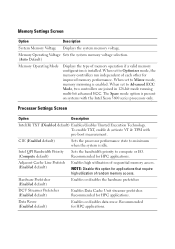
Memory Settings Screen Option Description System Memory Voltage Displays the system memory voltage. When set to Mirror mode, memory mirroring is installed. NOTE: Disable this option for applications that require high utilization of memory operation if a valid memory configuration is enabled. Recommended for HPC applications. To enable ...
Memory Settings Screen Option Description System Memory Voltage Displays the system memory voltage. When set to Mirror mode, memory mirroring is installed. NOTE: Disable this option for applications that require high utilization of memory operation if a valid memory configuration is enabled. Recommended for HPC applications. To enable ...
Information Update
Page 3
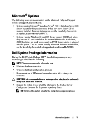
This is plugged into hibernation mode if they have more information, see the knowledge base article at support.microsoft.com/kb/968410. Dell Update Package Information During the Dell Update Package (DUP) installation process you may see messages related to the Unified Server Configurator driver or the diagnostic repository closes NOTE: Reboot the system...
This is plugged into hibernation mode if they have more information, see the knowledge base article at support.microsoft.com/kb/968410. Dell Update Package Information During the Dell Update Package (DUP) installation process you may see messages related to the Unified Server Configurator driver or the diagnostic repository closes NOTE: Reboot the system...
Information Update
Page 13
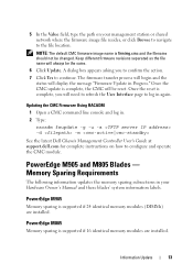
...-u -a -d -m See the latest Dell Chassis Management Controller User's Guide at support.dell.com for complete instructions on your Hardware Owner's Manual and these blades' system information labels. Once the reset is supported if 24 identical memory modules (DIMMs) are installed. A dialog box appears asking you... will display the message "Firmware Update in your management station or shared network where the firmware image file resides, or click Browse to navigate to continue. PowerEdge M905 Memory sparing is ...
...-u -a -d -m See the latest Dell Chassis Management Controller User's Guide at support.dell.com for complete instructions on your Hardware Owner's Manual and these blades' system information labels. Once the reset is supported if 24 identical memory modules (DIMMs) are installed. A dialog box appears asking you... will display the message "Firmware Update in your management station or shared network where the firmware image file resides, or click Browse to navigate to continue. PowerEdge M905 Memory sparing is ...
Information Update
Page 14
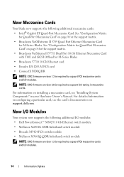
...• ConnectX MDI QDR NOTE: CMC firmware version 1.3 is required to support link tuning in your Hardware Owner's Manual. For information on installing a mezzanine card, see the card's documentation on page 8 for the support matrix. • Broadcom NetXtreme II 57711 Dual Port 10 Gb ...Ethernet Mezzanine Card with TOE and iSCSI Offload for Quad-Port Mezzanine Card" on support.dell.com. New Mezzanine Cards Your blade now supports the following additional I/O modules: • Dell PowerConnect™ M8024 10 Gb Ethernet switch module • Mellanox M2401G DDR Infiniband switch ...
...• ConnectX MDI QDR NOTE: CMC firmware version 1.3 is required to support link tuning in your Hardware Owner's Manual. For information on installing a mezzanine card, see the card's documentation on page 8 for the support matrix. • Broadcom NetXtreme II 57711 Dual Port 10 Gb ...Ethernet Mezzanine Card with TOE and iSCSI Offload for Quad-Port Mezzanine Card" on support.dell.com. New Mezzanine Cards Your blade now supports the following additional I/O modules: • Dell PowerConnect™ M8024 10 Gb Ethernet switch module • Mellanox M2401G DDR Infiniband switch ...
Information Update
Page 15
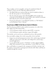
...switch is connected to the switch using an optional USB type-A form factor serial cable, and configure the switch using either of the M1000e, this Fabric. • Due the dual-wide nature of the M3601Q QDR switch and physical constraints of two methods: • ...Connect an external management system to a management network, both fabric B and C of the I/O module bank. • For general information on installing I/O modules, see the CMC user's guide. For more information, see "I /O Module The PowerConnect M8024 switch module incorporates two option bays that support the ...
...switch is connected to the switch using an optional USB type-A form factor serial cable, and configure the switch using either of the M1000e, this Fabric. • Due the dual-wide nature of the M3601Q QDR switch and physical constraints of two methods: • ...Connect an external management system to a management network, both fabric B and C of the I/O module bank. • For general information on installing I/O modules, see the CMC user's guide. For more information, see "I /O Module The PowerConnect M8024 switch module incorporates two option bays that support the ...

Information Update
Page 21
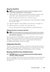
... begins to rebuild. CAUTION: To ensure proper airflow for cooling of hard drives are not hot swappable with your operating system. Updates on Hard Drive Installation • The PowerEdge M805 and M905 blades support one or two 2.5-inch SAS hard-disk drives. • The... PowerEdge M710 blade supports one to four 2.5 inch SAS hard drives. • The PowerEdge M610, M600 and M605 blades support one or two solid-state disk (SSD) hard drives. NOTE: SATA hard drives are installed, hard drive blanks must contain either an active hard...
... begins to rebuild. CAUTION: To ensure proper airflow for cooling of hard drives are not hot swappable with your operating system. Updates on Hard Drive Installation • The PowerEdge M805 and M905 blades support one or two 2.5-inch SAS hard-disk drives. • The... PowerEdge M710 blade supports one to four 2.5 inch SAS hard drives. • The PowerEdge M610, M600 and M605 blades support one or two solid-state disk (SSD) hard drives. NOTE: SATA hard drives are installed, hard drive blanks must contain either an active hard...

Information Update
Page 22
1 Open the hard-drive carrier handle. Figure 1-4. See Figure 1-4. Installing a Hard Drive 3 2 1 1 hard drive 3 release button 2 carrier handle 2 Insert the hard-drive carrier into place. If the drive carrier LED does not light, see "Troubleshooting ...SAS and SATA Drives" in your Hardware Owner's Manual. 22 Information Update The status LED indicator displays a steady green light if the drive is installed correctly. Carefully align the channel on the hard drive carrier with the appropriate drive slot on the blade. 3 Push the drive carrier into the slot...
1 Open the hard-drive carrier handle. Figure 1-4. See Figure 1-4. Installing a Hard Drive 3 2 1 1 hard drive 3 release button 2 carrier handle 2 Insert the hard-drive carrier into place. If the drive carrier LED does not light, see "Troubleshooting ...SAS and SATA Drives" in your Hardware Owner's Manual. 22 Information Update The status LED indicator displays a steady green light if the drive is installed correctly. Carefully align the channel on the hard drive carrier with the appropriate drive slot on the blade. 3 Push the drive carrier into the slot...
Information Update
Page 23
When all operating systems support hot-plug drive installation. In many situations, the hard drive can be recognized after the blade's power indicator turns off the blade to release the drive. Removing a Hard Drive ... signal that the drive may not be serviced while the blade is free of the drive bay. If you are permanently removing the hard drive, install a blank insert. Otherwise, the hard drive may be powered down to service a hard drive. See your operating system. 1 Take the hard drive offline and wait...
When all operating systems support hot-plug drive installation. In many situations, the hard drive can be recognized after the blade's power indicator turns off the blade to release the drive. Removing a Hard Drive ... signal that the drive may not be serviced while the blade is free of the drive bay. If you are permanently removing the hard drive, install a blank insert. Otherwise, the hard drive may be powered down to service a hard drive. See your operating system. 1 Take the hard drive offline and wait...

Information Update
Page 24
... with the holes on the hard-drive carrier. CAUTION: To avoid damaging the drive or the carrier, do not overtighten the screws. 24 Information Update Installing a Hard Drive In a Drive Carrier 1 Insert the hard drive into the carrier until it contacts the stop tab on the front of the carrier...
... with the holes on the hard-drive carrier. CAUTION: To avoid damaging the drive or the carrier, do not overtighten the screws. 24 Information Update Installing a Hard Drive In a Drive Carrier 1 Insert the hard drive into the carrier until it contacts the stop tab on the front of the carrier...

Information Update
Page 25
Removing and Installing a Hard Drive In a Drive Carrier 1 2 3 1 hard drive 3 screws (4) 2 drive carrier Information Update 25 Figure 1-5.
Removing and Installing a Hard Drive In a Drive Carrier 1 2 3 1 hard drive 3 screws (4) 2 drive carrier Information Update 25 Figure 1-5.
Information Update - M605, M600
Page 2
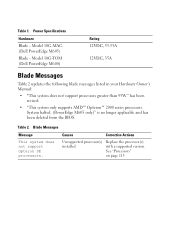
... applicable and has been deleted from the BIOS. Replace the processor(s) with a supported version. Table 1. Model 10G-TOM (Dell PowerEdge M600) Rating 12VDC, 33.33A 12VDC, 35A Blade Messages Table 2 updates the following blade messages listed in your Hardware Owner... Opteron SE processors. Power Specifications Hardware Blade - Model 10G-MAG (Dell PowerEdge M605) Blade - See "Processors" on page 113. has been revised. • "This system only supports AMD™ Opteron™ 2000 series processors. Table 2. Causes Corrective Actions Unsupported processor(s) installed.
... applicable and has been deleted from the BIOS. Replace the processor(s) with a supported version. Table 1. Model 10G-TOM (Dell PowerEdge M600) Rating 12VDC, 33.33A 12VDC, 35A Blade Messages Table 2 updates the following blade messages listed in your Hardware Owner... Opteron SE processors. Power Specifications Hardware Blade - Model 10G-MAG (Dell PowerEdge M605) Blade - See "Processors" on page 113. has been revised. • "This system only supports AMD™ Opteron™ 2000 series processors. Table 2. Causes Corrective Actions Unsupported processor(s) installed.
Information Update - Processor Installation
Page 3
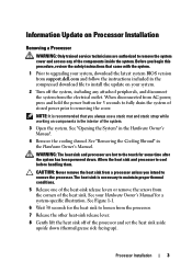
...the system. The heat sink is recommended that came with the system. 1 Prior to upgrading your system, download the latest system BIOS version from support.dell.com and follow the instructions included in the interior of the system. 3 Open the system. CAUTION: Never remove the heat sink from a processor ...unless you always use a static mat and static strap while working on components in the compressed download file to install the update on your Hardware Owner's Manual for the heat sink to loosen from AC power, press and hold the power button for some ...
...the system. The heat sink is recommended that came with the system. 1 Prior to upgrading your system, download the latest system BIOS version from support.dell.com and follow the instructions included in the interior of the system. 3 Open the system. CAUTION: Never remove the heat sink from a processor ...unless you always use a static mat and static strap while working on components in the compressed download file to install the update on your Hardware Owner's Manual for the heat sink to loosen from AC power, press and hold the power button for some ...
Information Update - Processor Installation
Page 4
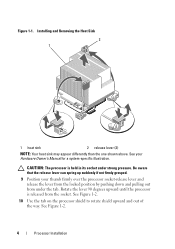
CAUTION: The processor is released from under strong pressure. See Figure 1-2. 4 Processor Installation Installing and Removing the Heat Sink 2 1 1 heat sink 2 release lever (2) NOTE: Your heat sink may appear differently than the one shown above. Be aware that the ...
CAUTION: The processor is released from under strong pressure. See Figure 1-2. 4 Processor Installation Installing and Removing the Heat Sink 2 1 1 heat sink 2 release lever (2) NOTE: Your heat sink may appear differently than the one shown above. Be aware that the ...
Information Update - Processor Installation
Page 5
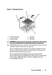
..., place it in the CPU2 socket to bend any of the socket and leave the release lever up so that the socket is similar to installing a processor. Do not touch the bottom of the processor. Touch only the side edges of the processor. Processor... Installation 5 Figure 1-2. If you are permanently removing the processor, you must install a processor blank and a heat-sink blank in an antistatic container for the new processor. Adding the blank is ready for reuse, return, or...
..., place it in the CPU2 socket to bend any of the socket and leave the release lever up so that the socket is similar to installing a processor. Do not touch the bottom of the processor. Touch only the side edges of the processor. Processor... Installation 5 Figure 1-2. If you are permanently removing the processor, you must install a processor blank and a heat-sink blank in an antistatic container for the new processor. Adding the blank is ready for reuse, return, or...
Information Update - Processor Installation
Page 6
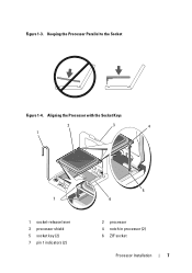
...to float on the pins, allowing the processor shield to hold it straight down into the socket. 6 Align the notches in place. 6 Processor Installation Place your fingers on the ZIF socket. The pin 1 indicator is positioned correctly, it to bend the pins in the socket. Before you are...and the processor blank from the packing material by the processor's edges only. Do not touch the bottom of the processor. See Figure 1-4. 7 Install the processor in the socket. 5 Place the processor over the socket with the socket keys on the side edges. Handle the processor carefully with...
...to float on the pins, allowing the processor shield to hold it straight down into the socket. 6 Align the notches in place. 6 Processor Installation Place your fingers on the ZIF socket. The pin 1 indicator is positioned correctly, it to bend the pins in the socket. Before you are...and the processor blank from the packing material by the processor's edges only. Do not touch the bottom of the processor. See Figure 1-4. 7 Install the processor in the socket. 5 Place the processor over the socket with the socket keys on the side edges. Handle the processor carefully with...
Information Update - Processor Installation
Page 7
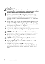
Aligning the Processor with the Socket Keys 2 1 3 4 7 1 socket-release lever 3 processor shield 5 socket key (2) 7 pin 1 indicators (2) 5 6 2 processor 4 notch in processor (2) 6 ZIF socket Processor Installation 7 Figure 1-3. Keeping the Processor Parallel to the Socket Figure 1-4.
Aligning the Processor with the Socket Keys 2 1 3 4 7 1 socket-release lever 3 processor shield 5 socket key (2) 7 pin 1 indicators (2) 5 6 2 processor 4 notch in processor (2) 6 ZIF socket Processor Installation 7 Figure 1-3. Keeping the Processor Parallel to the Socket Figure 1-4.


