
PowerEdge HS5620 Installation and Service Manual
Page 3
...this document...8 Chapter 2: Dell PowerEdge HS5620 system overview 9 Front view of the system...9 Left control panel view...12 Right control panel view...13 Rear view of the system...14 Inside the system ...16 Locating the Express Service Code and Service Tag 17 System information label...18 Rail sizing and rack compatibility matrix...21 Chapter 3: Technical specifications 23 Chassis dimensions ...24 System weight...24 Processor specifications...25 PSU specifications...25 Supported operating systems...26 Cooling fan specifications...26 System battery specifications...28 Expansion card riser...
...this document...8 Chapter 2: Dell PowerEdge HS5620 system overview 9 Front view of the system...9 Left control panel view...12 Right control panel view...13 Rear view of the system...14 Inside the system ...16 Locating the Express Service Code and Service Tag 17 System information label...18 Rail sizing and rack compatibility matrix...21 Chapter 3: Technical specifications 23 Chassis dimensions ...24 System weight...24 Processor specifications...25 PSU specifications...25 Supported operating systems...26 Cooling fan specifications...26 System battery specifications...28 Expansion card riser...

PowerEdge HS5620 Installation and Service Manual
Page 4
Chapter 5: Pre-operating system management applications 43 System Setup...43 System BIOS...44 iDRAC Settings...65 Device Settings...65 Dell Lifecycle Controller...65 Embedded system management...65 Boot Manager...65 PXE boot...66 Chapter 6: Minimum to POST and system management configuration validation 67 Minimum configuration to POST ...67 Configuration validation...67 Error messages...68 Chapter 7: Installing and removing system components 69 Safety instructions...69 Before working inside your system ...69 After working inside your system...70...
Chapter 5: Pre-operating system management applications 43 System Setup...43 System BIOS...44 iDRAC Settings...65 Device Settings...65 Dell Lifecycle Controller...65 Embedded system management...65 Boot Manager...65 PXE boot...66 Chapter 6: Minimum to POST and system management configuration validation 67 Minimum configuration to POST ...67 Configuration validation...67 Error messages...68 Chapter 7: Installing and removing system components 69 Safety instructions...69 Before working inside your system ...69 After working inside your system...70...
PowerEdge HS5620 Installation and Service Manual
Page 6
... 8: Upgrade Kits...167 Chapter 9: Jumpers and connectors 168 System board jumpers and connectors...168 System board jumper settings...170 Disabling a forgotten password...170 Chapter 10: System diagnostics and indicator codes 172 Status LED indicators...172 System health and system ID indicator codes...174 iDRAC Quick Sync 2 indicator codes...175 iDRAC Direct LED indicator codes...175 LCD panel...176 Viewing Home screen...177 Setup menu...177 View menu...177 NIC indicator codes...178 Power supply unit indicator codes...178 Drive indicator codes...180 Using system diagnostics...
... 8: Upgrade Kits...167 Chapter 9: Jumpers and connectors 168 System board jumpers and connectors...168 System board jumper settings...170 Disabling a forgotten password...170 Chapter 10: System diagnostics and indicator codes 172 Status LED indicators...172 System health and system ID indicator codes...174 iDRAC Quick Sync 2 indicator codes...175 iDRAC Direct LED indicator codes...175 LCD panel...176 Viewing Home screen...177 Setup menu...177 View menu...177 NIC indicator codes...178 Power supply unit indicator codes...178 Drive indicator codes...180 Using system diagnostics...

PowerEdge HS5620 Installation and Service Manual
Page 11
... Mobile (OMM) aggregates hardware or firmware inventory and various system level diagnostic and error information that are supported on certain configurations. ● Status LED: Enables you to identify any failed hardware components. For more information, see the Integrated Dell Remote Access Controller User's Guide available at https://www.dell.com/idracmanuals. 2 Drive N/A Enables you have opted for the secure default access to five status LEDs and an overall system health LED (Chassis health and system ID...
... Mobile (OMM) aggregates hardware or firmware inventory and various system level diagnostic and error information that are supported on certain configurations. ● Status LED: Enables you to identify any failed hardware components. For more information, see the Integrated Dell Remote Access Controller User's Guide available at https://www.dell.com/idracmanuals. 2 Drive N/A Enables you have opted for the secure default access to five status LEDs and an overall system health LED (Chassis health and system ID...

PowerEdge HS5620 Installation and Service Manual
Page 14
... by using a USB to micro USB (type AB) cable, which you to connect PCI Express expansion cards. Rear view of the system Item Ports, panels or slots 1 PCIe expansion card slot 1 Icon 2 PCIe expansion card slot 2 3 Expansion card riser with slot 3 and 4 4 PCIe expansion card slot 5 5 System identification button 14 Dell PowerEdge HS5620 system overview Description Enables you to connect PCI Express expansion card risers. NOTE: Press the power button to your laptop or tablet. For more information about ports, panels, and slots, see the Integrated Dell Remote Access...
... by using a USB to micro USB (type AB) cable, which you to connect PCI Express expansion cards. Rear view of the system Item Ports, panels or slots 1 PCIe expansion card slot 1 Icon 2 PCIe expansion card slot 2 3 Expansion card riser with slot 3 and 4 4 PCIe expansion card slot 5 5 System identification button 14 Dell PowerEdge HS5620 system overview Description Enables you to connect PCI Express expansion card risers. NOTE: Press the power button to your laptop or tablet. For more information about ports, panels, and slots, see the Integrated Dell Remote Access...

PowerEdge HS5620 Installation and Service Manual
Page 39
... must request for the settings at dell.com/poweredgemanuals. 3. Interfaces to set up iDRAC IP address Interface iDRAC Settings utility Documentation links Integrated Dell Remote Access Controller User's Guide at https://www.dell.com/idracmanuals or for system specific Integrated Dell Remote Access Controller User's Guide, go to the system. Initial system setup and configuration 39 Unpack the system. 2. For more information, see the documentation links provided in the table below . iDRAC configuration The Integrated Dell Remote Access Controller (iDRAC) is designed to...
... must request for the settings at dell.com/poweredgemanuals. 3. Interfaces to set up iDRAC IP address Interface iDRAC Settings utility Documentation links Integrated Dell Remote Access Controller User's Guide at https://www.dell.com/idracmanuals or for system specific Integrated Dell Remote Access Controller User's Guide, go to the system. Initial system setup and configuration 39 Unpack the system. 2. For more information, see the documentation links provided in the table below . iDRAC configuration The Integrated Dell Remote Access Controller (iDRAC) is designed to...

PowerEdge HS5620 Installation and Service Manual
Page 42
... to download and install OS drivers. Prerequisites Ensure that you download and install the latest BIOS, drivers, and systems management firmware on the system. Go to the system are applicable to www.dell.com/support/drivers. 2. On the displayed product page, click Drivers & Downloads. iDRAC virtual media Integrated Dell Remote Access Controller User's Guide at https://www.dell.com/idracmanuals or for latest documentation version, see the documentation links provided in the Enter a Dell Service Tag, Dell Product ID or Model...
... to download and install OS drivers. Prerequisites Ensure that you download and install the latest BIOS, drivers, and systems management firmware on the system. Go to the system are applicable to www.dell.com/support/drivers. 2. On the displayed product page, click Drivers & Downloads. iDRAC virtual media Integrated Dell Remote Access Controller User's Guide at https://www.dell.com/idracmanuals or for latest documentation version, see the documentation links provided in the Enter a Dell Service Tag, Dell Product ID or Model...

PowerEdge HS5620 Installation and Service Manual
Page 44
... video memory. Memory Operating Mode This field selects the memory operating mode. Specifies the contact information of the system memory. Table 39. System Setup Main Menu (continued) Option Device Settings Service Tag Settings Description Enables you to Disabled by select hypervisors for devices such as storage controllers or network cards. Enables you to create a fault resilient zone starting from lowest system memory address for use by default. Table 40. System Information details Option System Model Name System BIOS Version System Management Engine Version System Service...
... video memory. Memory Operating Mode This field selects the memory operating mode. Specifies the contact information of the system memory. Table 39. System Setup Main Menu (continued) Option Device Settings Service Tag Settings Description Enables you to Disabled by select hypervisors for devices such as storage controllers or network cards. Enables you to create a fault resilient zone starting from lowest system memory address for use by default. Table 40. System Information details Option System Model Name System BIOS Version System Management Engine Version System Service...
PowerEdge HS5620 Installation and Service Manual
Page 48
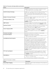
... CPU Crash Log Support PROCESSOR n Enables or disables the local machine check exception. This option is set to prefetech, when the Fill Buffers (FB) is enabled. NOTE: The processor bus speed option displays only when both processors are displayed for collection of previous crash data from 0 to all threads in a fatal machine check event. Controls the number of processors, there might be up to Auto by default. This option is set to two processor listings...
... CPU Crash Log Support PROCESSOR n Enables or disables the local machine check exception. This option is set to prefetech, when the Fill Buffers (FB) is enabled. NOTE: The processor bus speed option displays only when both processors are displayed for collection of previous crash data from 0 to all threads in a fatal machine check event. Controls the number of processors, there might be up to Auto by default. This option is set to two processor listings...

PowerEdge HS5620 Installation and Service Manual
Page 49
... system contains NVMe drives that you want to configure in a RAID array, you should set to Enabled by default. To view the NVMe Settings screen, power on the system, press F2, and click System Setup Main Menu > System BIOS > SATA Settings. You may also need to change the Boot Mode setting to RAID Mode. No ESXi and Ubuntu OS support under RAID mode. Table 43. For AHCI Mode, BIOS support is set the field to Off, AHCI mode , or RAID modes.
... system contains NVMe drives that you want to configure in a RAID array, you should set to Enabled by default. To view the NVMe Settings screen, power on the system, press F2, and click System Setup Main Menu > System BIOS > SATA Settings. You may also need to change the Boot Mode setting to RAID Mode. No ESXi and Ubuntu OS support under RAID mode. Table 43. For AHCI Mode, BIOS support is set the field to Off, AHCI mode , or RAID modes.
PowerEdge HS5620 Installation and Service Manual
Page 50
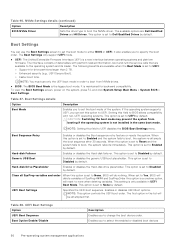
... of the system. It is set the boot mode of data tables with non-UEFI operating systems. This option is set to Enabled and the system fails to Disabled by default. When this field to None, BIOS will do nothing. Hard-disk Failover Enables or disables the Hard-disk failover. This option is set to UEFI disables the BIOS Boot Settings menu. NVMe Settings details (continued) Option Description BIOS NVMe Driver Sets the drive type to change the boot device order. This option is...
... of the system. It is set the boot mode of data tables with non-UEFI operating systems. This option is set to Enabled and the system fails to Disabled by default. When this field to None, BIOS will do nothing. Hard-disk Failover Enables or disables the Hard-disk failover. This option is set to UEFI disables the BIOS Boot Settings menu. NVMe Settings details (continued) Option Description BIOS NVMe Driver Sets the drive type to change the boot device order. This option is...

PowerEdge HS5620 Installation and Service Manual
Page 55
... not detect any USB devices installed in certain USB ports during POST. SecurityKeyPath Specifies the Securitykeypath for shared network access by iDRAC. Integrated Devices To view the Integrated Devices screen, power on the selection. Table 57. Integrated Devices details Option User Accessible USB Ports Description Configures the user accessible USB ports. The USB keyboard and mouse still function in this NVMe-oF connection. After the boot process is set to Disabled (operating system), the Integrated NICs might still be enabled or disabled...
... not detect any USB devices installed in certain USB ports during POST. SecurityKeyPath Specifies the Securitykeypath for shared network access by iDRAC. Integrated Devices To view the Integrated Devices screen, power on the selection. Table 57. Integrated Devices details Option User Accessible USB Ports Description Configures the user accessible USB ports. The USB keyboard and mouse still function in this NVMe-oF connection. After the boot process is set to Disabled (operating system), the Integrated NICs might still be enabled or disabled...

PowerEdge HS5620 Installation and Service Manual
Page 56
... the hardware and software support the feature. When set to Disabled by default. Enables or disables the BIOS configuration of the system. When this option is a set to accelerate network traffic and lower CPU utilization. Configure the Embedded NIC1 and NIC2 option by default. This setting can withhold snoop requests, from the CPU, to allow time to complete its pre-boot services will then be disabled only when the installed peripheral card prevents booting...
... the hardware and software support the feature. When set to Disabled by default. Enables or disables the BIOS configuration of the system. When this option is a set to accelerate network traffic and lower CPU utilization. Configure the Embedded NIC1 and NIC2 option by default. This setting can withhold snoop requests, from the CPU, to allow time to complete its pre-boot services will then be disabled only when the installed peripheral card prevents booting...

PowerEdge HS5620 Installation and Service Manual
Page 65
... the Dell Lifecycle Controller, configuring hardware and firmware, and deploying the operating system, see Dell Integrated Dell Remote Access Controller User's Guide at https://www.dell.com/idracmanuals. This option is set of features provided by using the iDRAC settings. For more information about using UEFI. LC is started during the boot sequence and functions independently of -band solution and Dell system embedded Unified Extensible Firmware Interface (UEFI) applications. The Dell Lifecycle Controller is delivered as storage controllers or network cards...
... the Dell Lifecycle Controller, configuring hardware and firmware, and deploying the operating system, see Dell Integrated Dell Remote Access Controller User's Guide at https://www.dell.com/idracmanuals. This option is set of features provided by using the iDRAC settings. For more information about using UEFI. LC is started during the boot sequence and functions independently of -band solution and Dell system embedded Unified Extensible Firmware Interface (UEFI) applications. The Dell Lifecycle Controller is delivered as storage controllers or network cards...

PowerEdge HS5620 Installation and Service Manual
Page 153
... redundant PSUs is enabled, one . Power supply unit NOTE: While replacing the hot swappable PSU, after next server boot; Installing and removing system components 153 Follow the procedure listed in the sleep state monitors output voltage of the active PSU drops, the PSU in the sleep state returns to the latest firmware and changing the configuration, see the Lifecycle Controller User's Guide at higher efficiency. For updating to an...
... redundant PSUs is enabled, one . Power supply unit NOTE: While replacing the hot swappable PSU, after next server boot; Installing and removing system components 153 Follow the procedure listed in the sleep state monitors output voltage of the active PSU drops, the PSU in the sleep state returns to the latest firmware and changing the configuration, see the Lifecycle Controller User's Guide at higher efficiency. For updating to an...
PowerEdge HS5620 Installation and Service Manual
Page 161
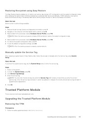
... replacing the system board. Power on the system. 2. Upgrading the Trusted Platform Module Removing the TPM Prerequisites 1. Installing and removing system components 161 All data is backed up in the backup flash device, BIOS prompts the user to manually enter the Service Tag, using Easy Restore The Easy Restore feature enables you enter the correct service tag. About this task Below is a service technician replaceable part only. Restore data from a previously created Hardware Server...
... replacing the system board. Power on the system. 2. Upgrading the Trusted Platform Module Removing the TPM Prerequisites 1. Installing and removing system components 161 All data is backed up in the backup flash device, BIOS prompts the user to manually enter the Service Tag, using Easy Restore The Easy Restore feature enables you enter the correct service tag. About this task Below is a service technician replaceable part only. Restore data from a previously created Hardware Server...

PowerEdge HS5620 Installation and Service Manual
Page 165
... control panel assembly and remove the control panel along with the cable from the system. 2. Installing and removing system components 165 Follow the safety guidelines listed in the Before working inside your system. 3. Removing the right control panel Next steps Replace the right control panel. Steps 1. Disconnect the control panel cable and the VGA cable from the system board connector and remove the cable from cable clip. Follow the safety guidelines listed in the Safety instructions...
... control panel assembly and remove the control panel along with the cable from the system. 2. Installing and removing system components 165 Follow the safety guidelines listed in the Before working inside your system. 3. Removing the right control panel Next steps Replace the right control panel. Steps 1. Disconnect the control panel cable and the VGA cable from the system board connector and remove the cable from cable clip. Follow the safety guidelines listed in the Safety instructions...
PowerEdge HS5620 Installation and Service Manual
Page 168
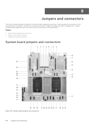
To install components and cables correctly, you must know the connectors on the various boards in the system. Topics: • System board jumpers and connectors • System board jumper settings • Disabling a forgotten password System board jumpers and connectors Figure 134. 9 Jumpers and connectors This topic provides some basic and specific information about jumpers and switches. System board jumpers and connectors 168 Jumpers and connectors It also describes the connectors on the system board. Jumpers on the system board help...
To install components and cables correctly, you must know the connectors on the various boards in the system. Topics: • System board jumpers and connectors • System board jumper settings • Disabling a forgotten password System board jumpers and connectors Figure 134. 9 Jumpers and connectors This topic provides some basic and specific information about jumpers and switches. System board jumpers and connectors 168 Jumpers and connectors It also describes the connectors on the system board. Jumpers on the system board help...

PowerEdge HS5620 Installation and Service Manual
Page 170
...BIOS password feature is disabled. Damage due to servicing that are cleared at system boot. PIB_SIG2 36. B6, B2, B8, B4 40. CAUTION: You should only perform troubleshooting and simple repairs as authorized in the setting might prevent your warranty. Prerequisites CAUTION: Many repairs may even result in use. x16 CPU2 Description Power Interposer Board signal cable connector 2 Intrusion switch cable connector System board power connector 1 PCIe cable connector (Processor 2) DIMMs for processor 2 Channels E, F, G, H PCIe cable connector (Processor 2) CMOS system battery...
...BIOS password feature is disabled. Damage due to servicing that are cleared at system boot. PIB_SIG2 36. B6, B2, B8, B4 40. CAUTION: You should only perform troubleshooting and simple repairs as authorized in the setting might prevent your warranty. Prerequisites CAUTION: Many repairs may even result in use. x16 CPU2 Description Power Interposer Board signal cable connector 2 Intrusion switch cable connector System board power connector 1 PCIe cable connector (Processor 2) DIMMs for processor 2 Channels E, F, G, H PCIe cable connector (Processor 2) CMOS system battery...
PowerEdge HS5620 Installation and Service Manual
Page 184
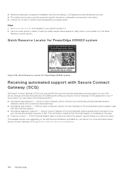
... 2. ● Reference materials, including the Installation and Service Manual, LCD diagnostics, and mechanical overview ● The system service tag to quickly access the specific hardware configuration and warranty information ● A direct link to Dell to Dell. When an issue is used by Dell Technical Support to your devices and uploads it securely to contact technical assistance and sales teams Steps 1. Quick Resource Locator for PowerEdge HS5620 system Figure 142. Go to...
... 2. ● Reference materials, including the Installation and Service Manual, LCD diagnostics, and mechanical overview ● The system service tag to quickly access the specific hardware configuration and warranty information ● A direct link to Dell to Dell. When an issue is used by Dell Technical Support to your devices and uploads it securely to contact technical assistance and sales teams Steps 1. Quick Resource Locator for PowerEdge HS5620 system Figure 142. Go to...


